
Related Manuals for AEMC 5050


Summary of Contents for AEMC 5050
- Page 1 5050 MEGOHMMETER 5060 E N G L I S H User Manual 0.561.8187 information@itm. www. .com...
- Page 2 Statement of Compliance Chauvin Arnoux , Inc. d.b.a. AEMC Instruments ® ® certifies that this instrument has been calibrated using standards and instruments traceable to international standards. We guarantee that at the time of shipping your instrument has met its published specifications.
-
Page 3: Table Of Contents
2.5.11 Voltage Disturbance Limit .............21 2.5.12 Automatic Measuring Range..........21 2.5.13 Blocking (Disabling) Test Voltages ........22 3. SPECIFICATIONS ................23 3.1 Reference Conditions.................23 3.2 Voltage ....................23 3.3 Insulation Resistance .................23 3.4 Power Supply ..................28 3.5 Environmental Specifications .............29 3.6 Mechanical Specifications ..............29 3.7 Safety Specifications ................29 3.8 Variations in Operating Range ............30 Megohmmeter Models 5050/5060 0.561.8187 information@itm. www. .com... - Page 4 ................46 ® 7.3.1 Configuring the Instrument............47 7.3.2 Running the Test ..............49 DataView Megohmmeter Templates ..........52 ® 7.4.1 Megohmmeter Summary Report Template ......52 8. MAINTENANCE ................54 8.1 Recharging the Battery ..............54 8.2 Fuse Replacement ................55 8.3 Cleaning .....................55 8.4 Storage....................55 Limited Warranty ..................57 Warranty Repairs ..................57 Megohmmeter Models 5050/5060 0.561.8187 information@itm. www. .com...
-
Page 5: Introduction
Risk of electric shock. The voltage at the parts marked with this symbol may be dangerous. In conformity with WEEE 2002/96/EC Megohmmeter Models 5050/5060 0.561.8187 information@itm. www. .com... -
Page 6: Definition Of Measurement Categories
NOTE: Charge the instrument fully before use. 1.4 Ordering Information Megohmmeter Model 5050.............Cat. #2130.20 Includes extra large classic tool bag, set of three 10 ft (5kV) leads (red/black/blue) with integral 5000V rated hippo clips, one guard terminal jumper lead, US 115V power cord, rechargeable battery pack, and user manual. -
Page 7: Accessory Information
200 Watt for Vehicle use ......Cat. #2135.43 Battery – Rechargeable 9.6V ............Cat. #2960.21 US 115V Power Cord ...............Cat. #5000.14 Adapter – RS-232 to USB 2.0 (5060) ..........Cat. #5000.60 1.5 Accessory Information 1.5.1 DataView Software ® (for Model 5060) Dataview software makes it possible to: ® • Retrieve data from memory and plot graphs of the changes in insulation as a function of the time over which the test voltage is applied, R(t). • Print out protocols of personalized tests, depending on the user’s needs. • Create text files for use on spreadsheets. • Set up and control the instrument entirely by the RS-232. Megohmmeter Models 5050/5060 0.561.8187 information@itm. www. .com... -
Page 8: Product Features
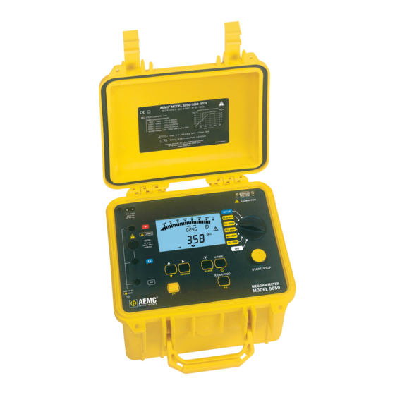
CHAPTER 2 PRODUCT FEATURES The Megohmmeter Models 5050 and 5060 are portable instruments, housed in rugged casing. These megohmmeters are designed to check the safety of electrical installations and equipment. Measures: • Voltage • Insulation Resistance • Capacitance • Leakage Current Advantages: • Automatic voltage detection in all functions, before or during the mea- surement, which inhibits or stops the measurement. - Page 9 MΩ - 5000V MΩ - 2500V FF 0.1A 380V - 10kA 5x20mm MΩ -1000V MΩ - 500V V/TIME SMOOTH ALARM START/STOP PRINT R-DAR-PI-DD 1000V CAT III 2500V MEGOHMMETER PRINT MEM R(t) MODEL 5060 Megohmmeter Models 5050/5060 0.561.8187 information@itm. www. .com...
-
Page 10: Megohmmeter Features
V/TIME - When measuring insulation, pressing this button displays the time elapsed since the beginning of the measurement, then the exact voltage generated. When performing resistance or capacitance measure- ment, this button has no effect. In MR (memory recall), it displays the date and time at which the measurement was stored, the exact test voltage and the OBJ : TEST number. • - Activates or deactivates the “time-controlled” test mode. • - Turns the display backlight ON or OFF. • ALARM - Activates or deactivates the alarms programmed in SET-UP. • - Selects a parameter to be modified. • SMOOTH - Stops/starts smoothing of displayed values during insulation testing. Megohmmeter Models 5050/5060 0.561.8187 information@itm. www. .com... -
Page 11: Digital Features
2.2 Digital Features min sec MEM MR OBJ. TEST GΩ TΩ MΩ kΩ DARDD µA nA µF ALARM SMOOTH REMOTE Main Display Indicates the value of: • Insulation measurement (resistance, DAR and PI, DD, capacitance). Small Display Indicates: • Voltage measured or applied by the instrument. • Elapsed time or the output voltage, during insulation measurement. After recording a set of data (5060), the small display also indicates the time and date in MR (memory recall) mode, and the memory address with the OBJ : TEST number. Megohmmeter Models 5050/5060 0.561.8187 information@itm. www. .com... -
Page 12: Bargraph
2 seconds when the instrument is turned on. The main display indicates “bat” when the test is carried on. Warning buzzer is activated. Indicates that the automatic switch-off function has been deactivated. SMOOTH: Smooths the insulation measurements displayed. REMOTE: Remote control via an interface (5060). In this mode, all the buttons and the rotary switch on the instrument are non-functional, except for the OFF position. FUSE -G-: Flashes if the “G” input fuse is defective. Megohmmeter Models 5050/5060 0.561.8187 information@itm. www. .com... -
Page 13: Push-Button Functions
MEM (memory storage) function. NOTE: If the selector switch’s position is altered, or if the STOP button is pressed during measurement, the measurement is interrupted. This function is only active for insulation measurement. Megohmmeter Models 5050/5060 0.561.8187 information@itm. www. .com... -
Page 14: R-Dar-Pi-Dd / R(T) Button
> 4 Excellent *The 10 and 1 minute times can be modified in the SET-UP menu, to adapt to any changes or specific applications. For multi-layer insulation, if one of the layers is defective, but all the others show strong resistance, the calculation of the PI and PAR ratios is not sufficient to show this type of problem. Therefore, it is necessary to supplement the PI and DAR indications by a dielectric discharge test (DD). This test measures the dielectric absorption of heterogeneous or multi-layer insu- lation while ignoring the parallel-surface leak currents. It consists of applying a test voltage for a period sufficient to electrically “charge” the insulation to be measured (a typical value is the application of a 500V voltage for 30 minutes). Megohmmeter Models 5050/5060 0.561.8187 information@itm. www. .com... - Page 15 NOTE: During the measurement, the DAR value is not available if the DD value was preselected before the measurement. The PI value is not available if DAR or DD values were preselected before the measurement. Megohmmeter Models 5050/5060 0.561.8187 information@itm.
- Page 16 DAR: Press START - the DAR symbol flashes and the display indicates “- - - -” as long as the calculation of the ratio is not possible (t <1 mn). e.g.: After 1 min, the measurement stops and the main display automatically shows the DAR value. During or after measurement, the R-DAR-PI-DD button can be used to see the insulation measurement carried out, but it does not give the PI value since the measurement has not lasted long enough. b) PI: Press START - the PI symbol flashes and the display indicates “- - - -” as long as the calculation of the ratio is not possible (t < programmed PI times). e.g.: After the upper PI time has passed, the measurement stops and the main display automatically shows the PI value. During and after measurement, the R-DAR- PI-DD button makes it possible to display the DAR (after 1 min), the PI and the insulation measurement. c) DD: Press START - the DD symbol flashes and the display indicates “- - - -” as long as the calculation of the ratio is not possible (t <30 min +1 min). e.g.: 1 minute after the measurement stops, the DD symbol becomes steady, the dis- play automatically show the value of DD. Megohmmeter Models 5050/5060 0.561.8187 information@itm. www. .com...
- Page 17 The time between each saved sample is programmed in the SET-UP menu. This function is also available on the Model 5050, which has neither a read-write memory for saving measured data, nor an interface for data retrieval from the instrument by a PC. Model 5050: Up to 20 samples can be recorded during measurement at the sample rate chosen in SET-UP (the default value is 30 seconds). It is possible to save more than 20 samples depending on available memory. Model 5060: The number of samples that can be saved is only limited by the memory space available. To enter the display mode, press the R(t) button: • The small display indicates the time 00:30 (e.g. the sampling frequency is every 30s). • The main display shows the corresponding R value. Megohmmeter Models 5050/5060 0.561.8187 information@itm. www. .com...
-
Page 18: Alarm Button
ACTIVATING THE ALARM INDICATION BEFORE A TEST To activate the Alarm Indication before performing a test you must go through the following steps: • Program the Alarm Set Point Resistance Value for the Test Voltage you will be using. • Turn the Rotary switch to the Setup position. • Press the Yellow 2 button and then the Alarm button to set Alarms. The first time you press 2 & Alarm you will see the alarm setting for 50 volt tests. • Press 2 & Alarm buttons repeatedly until you see the test you wish to set alarms for in the top line of the display. The sequencing will be 500, 1000, 2500, 5000, and set. • Use the cursor keys to adjust the Blinking value. First select KΩ, MΩ, GΩ or TΩ using the Up Arrow Key (). • Next, press the Right Arrow Key () to move to the next selection which is the greater than (>) / less than (<) choice. Use the Up Arrow Key to make your selection. Megohmmeter Models 5050/5060 0.561.8187 information@itm. www. .com... -
Page 19: Smooth Button
Selects the desired parameter to be modified - the selected parameter flashes. The flashing parameter is modified using the button (see § 2.5.6). Second Function - SMOOTH Activates a digital filter for insulation measurement. It only has an effect on the displayed values (which are smoothed) and not the actual measurements. For example, this function is useful when the displayed insulation values are highly unstable, brought about due to a capacitive component in the tested element. 2.5.6 Button Changes the flashing parameters displayed, or views R(t) values (see § 2.5.3). As a general rule, two figures (day, month, hour, min., sec., and OBJ:TEST) flash. The and functions have a “follow-on” mode. (e.g. as soon as the high or low program limit is reached, the parameter to be modified switches automatically to the following low or high limit.) Megohmmeter Models 5050/5060 0.561.8187 information@itm. www. .com... -
Page 20: Set-Up Function
The SET-UP function is used to directly access the parameters to be pro- grammed, by pressing the corresponding button. • After having pressed a button, the corresponding figures or symbols appear on the screen. • The figures or the symbols that can be modified, flash on the screen. • Use the buttons. • All the parameters are immediately and permanently saved. Megohmmeter Models 5050/5060 0.561.8187 information@itm. www. .com... - Page 21 40-5100V The values shown on this table, in the “Display/main” and “Display/small” columns, are the factory default values. In case they are accidentally changed, it is possible to get them back. (see § 2.5.10). Megohmmeter Models 5050/5060 0.561.8187 information@itm. www.
-
Page 22: Clearing The Memory
• “bAUd” appears on the small display. The value can be changed using the and buttons. • “Parallel” appearing in the display means that the parallel mode has been selected. This is for printing on a parallel printer via the serial-to- parallel adapter (RS-232 Centronics). 2.5.10 Default Device Configuration In SET-UP, press the button three times: • “SEt” appears in the small display. • “DFLt” (flashing) appears in the main display. Press START to select the default configuration settings (see the previous table). Megohmmeter Models 5050/5060 0.561.8187 information@itm. www. .com... -
Page 23: Voltage Disturbance Limit
NOTE: The fixed measurement ranges correspond to the current ranges of the following measurements: 1: 50pA to 200nA (>500GΩ) 2: 150nA to 50µA (500KΩ to 500GΩ) 3: 30µA to 3mA (<500KΩ) The choice of a fixed measurement range optimizes the measurement build-up time for a known value of insulation resistance. Example: Choice of range 1 for a measurement greater than 500GΩ. Note: In most cases, “Auto” should be selected. Megohmmeter Models 5050/5060 0.561.8187 information@itm. www. .com... -
Page 24: Blocking (Disabling) Test Voltages
500V for the 500V switch position on the rotary switch, and at 750V for all the other positions on the rotary switch (LIM will appear for 3 seconds on the main display). Megohmmeter Models 5050/5060 0.561.8187 information@itm. www. -
Page 25: Specifications
*Over 500Hz, the small display indicates “- - - -” and the main display gives only an assessment of the peak value of the measured voltage. Measurement Category: 1000V CAT III or 2500V CAT I (transients ≤2.5kV) 3.3 Insulation Resistance Method: Voltage-current method according to EN 61557-2 (ed. 02/97) Nominal Output Voltage: 500, 1000, 2500, 5000V (or adjustable from 40 to 5100V) No Adjustment in Variable Mode: 10V from 40 to 1000V 100V from 1000 to 5100V Open-circuit Voltage: ≤1.1 x Vn ±2V (Vn ±2% in variable mode) Megohmmeter Models 5050/5060 0.561.8187 information@itm. www. .com... -
Page 26: Measurement Ranges
4.00 to 40.0 to 400GΩ to 4.00 to Range 2.000 to 3.999TΩ 3.999GΩ 39.99GΩ 399.9GΩ 1.999TΩ 10.00TΩ Resolution 1MΩ 10MΩ 100MΩ 1GΩ 10GΩ Accuracy ±5% of Reading + 3cts ±15% of Reading + 10cts Megohmmeter Models 5050/5060 0.561.8187 information@itm. www. .com... - Page 27 Typical discharge time for a capacitive component to reach 25V Initial Voltage 500V 1000V 2500V 5000V Discharge time (C in µF) C x 3s C x 4s C x 4s C x 7s Megohmmeter Models 5050/5060 0.561.8187 information@itm. www. .com...
- Page 28 Typical changes in test voltages as a function of the load: 500V Range 0.01 Resistance (MΩ) 1000V Range 1200 1000 0.01 Resistance (MΩ) Megohmmeter Models 5050/5060 0.561.8187 information@itm. www. .com...
- Page 29 Typical changes in test voltages as a function of the load (cont.): 2500V Range 3000 2500 2000 1500 1000 Resistance (MΩ) 5000V Range 6000 5000 4000 3000 2000 1000 Resistance (MΩ) Megohmmeter Models 5050/5060 0.561.8187 information@itm. www. .com...
-
Page 30: Power Supply
Minimum Battery Charge Life (per NF EN 61557-2) Number of Measurements Test Voltage Nominal Charge 5s on nominal charge (with 25s pause between each measurement) 500V 500kΩ 6500 1000V 1MΩ 5500 2500V 2.5MΩ 4000 5000V 5MΩ 1500 Megohmmeter Models 5050/5060 0.561.8187 information@itm. www. .com... -
Page 31: Environmental Specifications
3.5 Environmental Specifications Operating Range: 14° to 104°F (-10° to 40°C) during recharging of batteries 14° to 131°F (-10° to 55°C) during measurement 10 to 80% RH Storage: -40 to 158°F (-40 to 70°C); 10 to 90% RH Altitude: <2000m 3.6 Mechanical Specifications Case Dimensions: 10.63 x 9.84 x 7.09" (270 x 250 x 180mm) Weight: 9.5 lbs (4.3kg) approx. Mechanical Protection IP 53 per NF EN 60529 (Ed. 92) IK 04 per NF EN 50102 (Ed. 95) 3.7 Safety Specifications Electrical safety according to EN 61010-1 (Ed. 2 for 2001), EN 61557 (ed. 97) 1000V CAT III, Pollution Degree 2 2500V CAT I Electromagnetic Compatibility: NF EN 61326-1 (Ed. 97) + A1, industrial environment category Megohmmeter Models 5050/5060 0.561.8187 information@itm. www. .com... -
Page 32: Variations In Operating Range
0% to 20% Vn MΩ 0.1% R / % Vn ± 5cts on test voltage *The terms DAR, PI, DD and the capacity and current leak measurements are included in the quantity “MΩ”. Megohmmeter Models 5050/5060 0.561.8187 information@itm. www. .com... -
Page 33: Measurement Functions
If, during insulation measurement, an external voltage higher than the value defined by the following threshold is detected, the mea- surement is stopped as long as the voltage is applied to the instrument. Megohmmeter Models 5050/5060 0.561.8187 information@itm. - Page 34 * The value of DD is displayed only one minute after the measurement stops. **Capacitance (µF) measurement is only displayed after the measurement is finished and the circuit has been discharged. Megohmmeter Models 5050/5060 0.561.8187 information@itm. www.
-
Page 35: Operation
• Start the measurement using the START/STOP button and read the results. WARNING: If an external voltage is present that is greater than the thresholds described in § 4.2, then measurement is prohibited. Megohmmeter Models 5050/5060 0.561.8187 information@itm. www. .com... -
Page 36: Operation Examples
MΩ - 5000V MΩ - 2500V FF 0.1A 380V - 10kA 5x20mm MΩ -1000V MΩ - 500V V/TIME SMOOTH ALARM START/STOP PRINT R-DAR-PI-DD 1000V CAT III 2500V MEGOHMMETER PRINT MEM R(t) MODEL 5060 Megohmmeter Models 5050/5060 0.561.8187 information@itm. www. .com... -
Page 37: Capacitance Measurement
1000V CAT III 2500V MEGOHMMETER PRINT MEM R(t) MODEL 5060 5.4 Capacitance Measurement Capacitance measurement is automatically carried out during insulation mea- surement. It is displayed after the measurement is stopped and the circuit is dis- charged, using the R-DAR-PI-DD button. 5.5 Residual and Leakage Current Measurement The measurement of residual current circulating in the installation is automatically made during an insulation measurement. It is displayed at the end of the measure- ment with the R-DAR-PI-DD button. Megohmmeter Models 5050/5060 0.561.8187 information@itm. www. .com... -
Page 38: Memory / Rs-232 (5060)
To be able to save your measurements, you will need to do the following: Set the instrument to SET-UP and press the MEM button (the display shows “MEM All clr”). Press the MEM button for 2s (the display shows “MEM ALL FrEE”). Mea- surements are now ready to be saved. First Function - MEM (Save) Results can be recorded in the instrument’s memory and stored along with addresses defined by an object number (OBJ) and a test number (TEST). An object represents a ‘box’ into which we can place 99 tests. Thus, an object can represent a machine or an installation upon which a certain number of measure- ments (insulation, resistance and continuity) are carried out. Megohmmeter Models 5050/5060 0.561.8187 information@itm. www. .com... - Page 39 • Total memory space: 128kb • Data management: 8kb • Free memory space: 120kb An insulation measurement requires 80 bytes. A “time-controlled test” sample requires 10 additional bytes. Therefore, it is possible to record about 1500 insula- tion measurements. Free Memory Space This function is automatically activated when a result is saved. Press MEM once to get the following free OBJ : TEST number; the bargraph dis- played corresponds to the available free memory space. • If the entire memory is free, all of the bargraph segments appear. • If the entire memory is full, the arrow to the left of the bargraph flashes. • As soon as the storage is complete, the bargraph disappears. Each segment of the bargraph equals approximately 50 recordings. Megohmmeter Models 5050/5060 0.561.8187 information@itm. www. .com...
-
Page 40: Printing Measured Values
• Printing of recorded data (PRINT memory) NOTE: If the data transmission to the printer is successful, the COM symbol flashes once on the screen. If a problem has occurred, the COM symbol remains on the LCD screen without flashing. Megohmmeter Models 5050/5060 0.561.8187 information@itm. www. -
Page 41: Instantaneous Printing Of Measurements (Print Button)
After a ‘time-controlled test’ other results are printed (interval samples): Time Resistance Voltage 0 0 : 30 35.94 GOhm 1005V 0 1 : 00 42.00 GOhm 1005V 0 1 : 30 43.50 GOhm 1005V etc... A space for the operator’s signature is available at the end of the printout. Megohmmeter Models 5050/5060 0.561.8187 information@itm. www. .com... -
Page 42: Printing Data In Memory (Print Mem Button)
Relative humidity: ........% Test voltage: ........5000 V Insulation resistance (IR): ....3.85 TΩ DAR: .............1.234 PI: ............2.382 DD: ..............Capacitance:..........µF I residual: ........... nA Comments: ..........................Date of next test: ..........OBJECT: 01 ........TEST: 02 Date: ..........03.31.2001 Starting time: ........15h 10 Running time: ......15 min 30 sec Megohmmeter Models 5050/5060 0.561.8187 information@itm. www. .com... - Page 43 Insulation resistance (IR): ....3.85 GΩ DAR: .............1.234 PI: ............2.345 DD: ..............Capacitance:..........µF I residual: ........... nA Comments: ..........................Date of next test: ..........A space for the operator’s signature is available at the end of the printout. Megohmmeter Models 5050/5060 0.561.8187 information@itm. www. .com...
-
Page 44: Dataview ® Software
NOTE: When installing, the user must have Administrative access rights during the installation. The users access rights can be changed after the installation is complete. DataView must be reinstalled for each user in a multi-user system. ® USB Flash Drive Install 1. Insert the USB stick into an available USB port (wait for driver to be installed). 2. If Autorun is enabled then an AutoPlay window should appear as shown. Megohmmeter Models 5050/5060 0.561.8187 information@itm. www. .com... - Page 45 Reader to the computer. Adobe Reader is required for ® ® viewing PDF documents supplied with DataView ® • *DataView Updates - Links to the online DataView software updates to ® check for new software version releases. • *Firmware Upgrades - Links to the online firmware updates to check for new firmware version releases. Megohmmeter Models 5050/5060 0.561.8187 information@itm. www. .com...
- Page 46 NOTE: The PDF-XChange option must be selected to be able to generate PDF reports from within DataView ® Figure 7-2 12. In the Ready to Install the Program window, click on Install. 13. If the instrument selected for installation requires the use of a USB port, a warning box will appear, similar to Figure 7-3. Click OK. Megohmmeter Models 5050/5060 0.561.8187 information@itm. www. .com...
- Page 47 NOTE: If you connected your instrument to the computer before installing the software and drivers, you may need to use the Add/Remove Hardware utility to remove the instrument driver before repeating the process. Megohmmeter Models 5050/5060 0.561.8187 information@itm. www.
-
Page 48: Connecting The Model 5060 To Your Computer
• DataView will open and display the DataView Quick Start window ® (see Figure 7-4). • Click the Configure Instrument button and the Connection window will appear (see Figure 7-5). The Quick Start Dialog Box contains the following options: • Configure Instrument: Creates a configuration for the megohmmeter. • Create View from Template: Creates a printable report from existing data already stored on the computer. Megohmmeter Models 5050/5060 0.561.8187 information@itm. www. .com... -
Page 49: Configuring The Instrument
Configuring the Instrument To configure the instrument, perform the following steps. 1. Click the Configure Instrument button. A dialog box will open, allowing you to select the Communication Rate and the Serial Port for communicating with the Model 5060. Figure 7-5 2. Make sure that the serial port displayed in the dialog box matches the port you plugged the serial cable into. If the correct serial port is not selected, click on the drop down arrow and select the proper one. 3. The Communication Rate will default to 9600 and should be acceptable to any computer. This is also the default rate for the Model 5060. You may select a different rate by clicking on the Communication Rate drop-down menu and selecting from the available values. 4. Once the proper communication parameters have been specified click on the OK button. Megohmmeter Models 5050/5060 0.561.8187 information@itm. www. .com... - Page 50 Each field in the dialog box is identical to the programmable features available from the instrument front panel itself. Refer to § 2.5 for a complete description of each configurable function. Several of the functions are configured by typing the appropriate value in the field provided, such as test run time, which may be programmed from a value of one minute to 59 minutes 59 seconds. Others are configured by clicking on the appropriate radio button, such as, activat- ing or deactivating the buzzer by either selecting ON or OFF. The right hand side of this setup dialog box contains nine command buttons: Close: Closes the Configuration dialog box and will bring up the Control • Panel. Write to Inst: Programs the megohmmeter using the current settings. • • Read from Inst: Reads the current configuration of the megohmmeter attached via the serial cable. Megohmmeter Models 5050/5060 0.561.8187 information@itm. www. .com...
-
Page 51: Running The Test
You can toggle between both windows via the Windows taskbar at the bottom of your screen. 7.3.2 Running the Test After configuring the instrument (see § 7.3.1), the Control Panel will automatically open. The Control Panel is used to initiate a timed test from the computer. The Control Panel dialog box consists of five command buttons: • Start: This button begins a timed test. • Clear Display: Clears the statistical data, on the lower left side of the screen, and the graph, on the right side of the screen. • Save to Disk: Saves the current data to a file in the computer. Megohmmeter Models 5050/5060 0.561.8187 information@itm. www. .com... - Page 52 NOTE: On small motors and machinery it is possible that the capacitance values are too low for this test to be completed accurately. In these cases, simply press the Stop button to stop the dielectric discharge test. Megohmmeter Models 5050/5060 0.561.8187 information@itm.
- Page 53 9. In the Groups window of this dialog box, click on “megohmmeter” then select the desired template, if other than the default is desired. 10. In Step 2: Specify Database(s) window, the file you just saved and named should be visible. If this is the file you wish to generate a report from, click the OK button. The report will now be available on the screen including graph, individual data points and all statistical data. 11. To print this report, either click on the Print icon or click on the File command and then Print. Megohmmeter Models 5050/5060 0.561.8187 information@itm. www. .com...
-
Page 54: Dataview ® Megohmmeter Templates
This worksheet contains the following frames: Trend Graph: This frame provides a graph of the measurement points in • the selected test. • Channel Summary: This frame displays a textual summary of the selected test. Channel List: This frame displays a list of tests. If more than one test • is listed you can display the results of each test by selecting it with the mouse pointer. • Trend Summary List: This frame displays a textual list summary of the sample points for a selected test. Each summary line contains user-spec- ified parameters of a group of sample points. An example of the last worksheet is shown in Figure 7-10. Megohmmeter Models 5050/5060 0.561.8187 information@itm. www. .com... - Page 55 Figure 7-10 Τhis page contains the following frames: • Title Box - containing the text “Trend Summary Report” Operator Summary - containing operator information • • Site Summary - containing test site information Comments Summary - containing typed in operator comments • • Database - containing the name of the database used to generate the report Each of these frames is customized by using the associated properties dialog box. The properties dialog box for a frame is displayed by selecting the frame, right- clicking and selecting Properties from the list displayed. Megohmmeter Models 5050/5060 0.561.8187 information@itm. www. .com...
-
Page 56: Maintenance
NOTE: The battery should only be changed by an authorized repair facility recog- nized by AEMC Instruments. ® Changing the battery causes data to be lost from the memory. Press the MEM /MR button (“OFF” is displayed). Proceed with a total clearing of memory in SET-UP (see § 2.5.7) so the MEM /MR functions can be used again. Megohmmeter Models 5050/5060 0.561.8187 information@itm. www. .com... -
Page 57: Fuse Replacement
Make sure that none of the terminals are connected and that the selector switch is set to OFF before opening up the case. Only use the type of fuse shown on label inside the unit’s cover: 0.1A - Fast Acting - 380V, 5x20mm, 10kA 8.3 Cleaning Disconnect the instrument from any source of electricity. Use a soft cloth lightly dampened with soapy water. Rinse with a wet cloth and then dry with a dry cloth. Do not use alcohol, solvents or hydrocarbons. 8.4 Storage If the instrument is not used for an extended period of time, it is recommended to charge the instrument every two or three months. Megohmmeter Models 5050/5060 0.561.8187 information@itm. www. .com... - Page 58 0.561.8187 information@itm. www. .com...
-
Page 59: Limited Warranty
Instruments ® ® 15 Faraday Drive • Dover, NH 03820 USA Phone: (800) 945-2362 (Ext. 360) (603) 749-6434 (Ext. 360) Fax: (603) 742-2346 or (603) 749-6309 E-mail: repair@aemc.com Caution: To protect yourself against in-transit loss, we recommend you insure your returned material. NOTE: You must obtain a CSA# before returning any instrument. Megohmmeter Models 5050/5060 0.561.8187 information@itm. www. .com... - Page 60 10/15 99-MAN 100258 v23 Chauvin Arnoux , Inc. d.b.a. AEMC Instruments ® ® 0.561.8187 information@itm. www. .com...
Need help?
Do you have a question about the 5050 and is the answer not in the manual?
Questions and answers