
Related Manuals for XIMEA xiQ series


Summary of Contents for XIMEA xiQ series
-
Page 1: Introduction
[ksi-kju: or sai-kju:] • USB 3.0 camera series Technical Manual Version 1.02, July 1 , 2013... -
Page 2: About This Manual
The purpose of this document is to provide a description of the XIMEA xiQ-Series cameras and to describe the correct way to install related software and drivers and run it successfully. Please read this manual thoroughly before operating your new camera for the first time. -
Page 3: Standard Conformity
A shielded I/O Sync cable ref. CBL-MQSYNC-3M0 (3m) Warning: Changes or modifications to the product may render it ineligible for operation under CE, FCC or other jurisdictions. XIMEA recommends using the above configuration to ensure compliance with the following standards: 1.3.1. -
Page 4: For Customers In Canada
GenICam GenTL API GenICam/GenTL GenICam standard transport layer interface, grabbing images. provides an agnostic transport layer interface to acquire images or other data and to communicate with a device. Each XIMEA camera can be GenTL Producer. 1.4. Helpful Links •... -
Page 5: Table Of Contents
1.4.1. Table of Contents Introduction ................................1 1.1. About This Manual ............................. 2 1.2. About XIMEA ..............................2 1.2.1. Contact XIMEA ............................2 1.3. Standard Conformity ............................3 1.3.1. CE Conformity ............................3 1.3.2. For customers in the US: FCC Conformity ....................3 1.3.3. - Page 6 3.5.2.4. Mechanical drawings (CS-mount [without C/CS mount module B]) ............ 24 3.5.2.5. Referenced documents ........................25 3.5.2.6. Sensor features..........................25 3.5.2.7. Note: horizontal image lines (MQ013CG-E2, MQ013MG-E2) ............. 25 3.5.2.8. Note: triggered exposure ........................ 25 3.5.2.9. Frame rate examples ........................25 3.5.3.
- Page 7 3.8.4.4. Digital Output – Wiring ........................42 3.8.4.5. Digital Output – Timing ........................47 3.9. CBL-U3-3M0 / CBL-U3-5M0 / CBL-U3-8M0 ..................... 48 3.10. CBL-U3-3M0-ANG ............................49 3.11. CBL-MQSYNC-3M0 ............................51 3.12. Tripod Adapter – MQ-BRACKET-T ........................52 3.12.1. Mechanical drawings (Brackets for MQ013xG-yy and MQ042xG-CM)............52 3.12.2.
- Page 8 5.2.30. Voyant Vision ............................76 5.3. Windows software package ..........................76 5.3.1. Contents ..............................76 5.3.2. Installation .............................. 77 5.3.3. XIMEA Viewer ............................80 5.3.3.1. xiViewer ............................80 5.3.3.2. New CCD Test ..........................81 5.4. Linux Software Package ........................... 81 5.4.1.
- Page 9 Step 2 - Create Product Service Request (PSR) ..................94 6.2.3. Step 3 - Wait for PSR Approval ........................ 94 6.2.4. Step 4 - Sending the camera to XIMEA ..................... 94 6.2.5. Step 5 - Waiting for Service Conclusion ....................94 6.2.6.
- Page 10 Warranty ................................. 97 6.5. Disclaimer of Warranty ............................. 97 6.6. List Of Trademarks ............................97 6.7. Standard Terms & Conditions of XIMEA GmbH ....................97 6.8. Copyright ..............................103 6.9. Revision History ............................. 103 Glossary ................................. 104 list of figures ................................105 list of tables ................................
-
Page 11: Xiq Camera Series
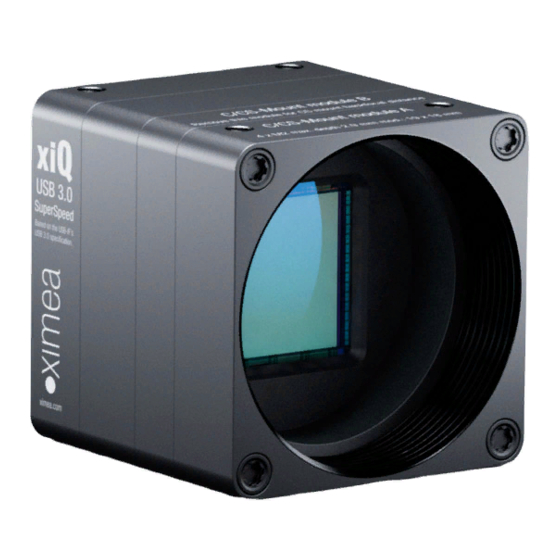
xiQ Camera Series 2.1. What is xiQ xiQ [ ksi-kju: or sai-kju:] is an ultra-compact USB 3.0 Industrial camera family with outstanding features: • Extremely small footprint • Lowe thermal dissipation • Single PC board electronics • USB3 Vision Standard compatible •... -
Page 12: Usb3 Vision Camera Applications
2.3. USB3 Vision Camera Applications • Automation • Ultra-fast 3D scanning • Miniature and fast robotic arms • Mobile devices • In-situ optical inspection camera • Material and Life science microscopy • Ophthalmology and Retinal imaging • Broadcasting • Fast process capture, e.g. golf club swings •... -
Page 13: Model Nomenclature
2.5. Model Nomenclature Order numbers name conventions for the different models: MQxxxyG-zz[-OPT] MQ: xiQ family name xxx: Resolution in 0.1 MPixel. E.g. 1.3 MPixel Resolution: xxx = 013 y=C: color model y=M: black & white model y=R: black & white, Infrared-extended model zz: Vendor of the sensor zz = E2: E2V zz = CM: CMOSIS... -
Page 14: Models Overview, Sensor And Models
2.6. Models Overview, sensor and models Optical Sensor Model Resolution Pixel size ADC [bit] size diagonal MQ003MG-CM 648x488 7.4 µm 10/12 66 dB 1/3” 6.0 mm >500 MQ003CG-CM Color MQ013MG-E2 MQ013CG-E2 Color 1280x1024 5.3 µm 66 dB 1/1.8” 8.7 mm MQ013RG-E2 b/w NIR MQ013MG-ON... -
Page 15: Accessories
3.0m USB 3.0 cable, angled micro USB3 connector CBL-U3-5M0 5.0m USB 3.0 cable CBL-U3-8M0 8.0m USB 3.0 cable CBL-MQSYNC-3M0 3.0m xiQ series I/O sync cable, pig tail MQ-BRACKET-T xiQ series tripod mounting bracket U3PE-FL1009 PCI express adapter, 2x USB 3.0 ports U3PE-D720202-X4 PCI express adapter, 4x USB 3.0 ports, PCIe x4 slot... -
Page 16: Hardware Specification
0 to 100 % Gamma 0.3 to 1.0 Full color correction matrix (3+1)x3 coefficients ranges -3.9 to 3.9 table 3-2, firmware / API features More details on API/SDK features are available at XIMEA support pages: http://www.ximea.com/support xiQ - Technical Manual Version 1.0... -
Page 17: Lens Mount
3.3. Lens Mount The xiQ cameras are compatible with C-mount and CS-mount lenses. front view side view figure 3-1, position C/CS-Mount module B The cameras are delivered with C-mount back focal length. By removing the “C/CS-Mount module B” (see the figure above) the camera can be rebuilt to CS-mount compatibility. -
Page 18: Optical Path
3.4. Optical path 3.4.1. Monochrome and near infrared extended camera models Used filter brand BK7 AR2x Thickness 1.0±0.1 mm Coating Anti-reflex both sides table 3-4, monochrome camera - filter glass parameter BK7 AR2x - Transmission Curve 350 400 450 500 550 600 650 700 750 800 850 900 950 1000 1050 Wavelength (nm) figure 3-3, monochrome camera - filter glass transmission curve 3.4.2. -
Page 19: Model Specific Characteristics
3.5. Model Specific Characteristics 3.5.1. MQ003xG-CM 3.5.1.1. Sensor and camera parameters xiQ model MQ003CG-CM MQ003MG-CM Sensor parameter (*1) Brand CMV300ES-3E7C1WP CMV300ES-3E7M1WP Color filter RGB Bayer mosaic None Type Global shutter, overlap mode Pixel Resolution (H × V) [pixel] 648 × 488 Active area size (H ×... -
Page 20: Quantum Efficiency Curves [%]
3.5.1.2. Quantum efficiency curves [%] CMV300 - Spectral Response Monochrome 1000 1050 Wavelength (nm) figure 3-5, CMV300-mono, quantum efficiency curve, ©CMOSIS 3.5.1.3. Mechanical drawings (C-mount [with C/CS mount module B]) figure 3-6, mechanical drawing MQ003xG-CM, C-Mount housing xiQ - Technical Manual Version 1.0... -
Page 21: Mechanical Drawings (Cs-Mount [Without C/Cs Mount Module B])
3.5.1.4. Mechanical drawings (CS-mount [without C/CS mount module B]) figure 3-7, mechanical drawing MQ003xG-CM, CS-Mount housing 3.5.1.5. Referenced documents CMOSIS Datasheet CMV300-datasheet-v2.0 (05/06/13) 3.5.1.6. Sensor features feature Note Binning Skipping Not supported, yet Single window in y direction supported, (cropping in X by xiAPI planned) HW Trigger Trigger with overlap (see 4.3.2.4 Triggered mode with overlap) Knee point based HDR (beta stage), see 4.4.9 HDR... -
Page 22: Mq013Xg-E2
3.5.2. MQ013xG-E2 3.5.2.1. Sensor and camera parameters xiQ model MQ013CG-E2 MQ013MG-E2 MQ013RG-E2 Sensor parameter Brand EV76C560ACT-EQV EV76C560ABT-EQV EV76C661ABT-EQTR Color filter RGB Bayer mosaic None None Type Global shutter, overlap mode Pixel Resolution (H × V) [pixel] 1280 × 1024 Active area size (H × V) [mm] 6.9 ×... -
Page 23: Quantum Efficiency Curves [%]
3.5.2.2. Quantum efficiency curves [%] EV76C560 - Spectral Response Monochrome Red Bayer Green Bayer Blue Bayer 1000 1050 Wavelength (nm) figure 3-8, EV76C560-mono and color, quantum efficiency curves, ©E2V EV76C560 / 661 - Spectral Response 560 Mono 661 Mono 1000 1050 Wavelength (nm) figure 3-9, EV76C560-mono and EV76C661-NIR, quantum efficiency curves, ©E2V xiQ - Technical Manual Version 1.0... -
Page 24: Mechanical Drawings (C-Mount [With C/Cs Mount Module B])
3.5.2.3. Mechanical drawings (C-mount [with C/CS mount module B]) figure 3-10, mechanical drawing MQ013xG-E2, C-Mount housing 3.5.2.4. Mechanical drawings (CS-mount [without C/CS mount module B]) figure 3-11, mechanical drawing MQ013xG-E2, CS-Mount housing xiQ - Technical Manual Version 1.0... -
Page 25: Referenced Documents
3.5.2.5. Referenced documents E2V Datasheet EV76C56 1005A–IMAGE–29/06/09 3.5.2.6. Sensor features feature Note Binning Yes, 2x2 binning supported Skipping Not supported yet 1 ROI with free parameters supported HW Trigger Trigger without overlap usable (see 4.3.2.3 Triggered mode without overlap) Currently not supported table 3-9, sensor features available 3.5.2.7. -
Page 26: Mq013Xg-On
3.5.3. MQ013xG-ON 3.5.3.1. Sensor and camera parameters xiQ model MQ013CG-ON MQ013MG-ON Sensor parameter (*1) Brand NOIV1SE1300A-QDC NOIV1SN1300A-QDC Color filter RGB Bayer mosaic None Type Global shutter, overlap mode Pixel Resolution (H × V) [pixel] 1280 × 1024 Active area size (H × V) [mm] 4.8 ×... -
Page 27: Quantum Efficiency Curves [%]
3.5.3.2. Quantum efficiency curves [%] VITA1300 - Spectral Response Monochrome Red Bayer Green Bayer Blue Bayer 1000 1050 Wavelength (nm) figure 3-12 VITA1300 mono and color, quantum efficiency curves, ©Onsemi 3.5.3.3. Mechanical drawings (C-mount [with C/CS mount module B]) figure 3-13, mechanical drawing MQ013xG-ON, C-Mount housing xiQ - Technical Manual Version 1.0... -
Page 28: Mechanical Drawings (Cs-Mount [Without C/Cs Mount Module B])
3.5.3.4. Mechanical drawings (CS-mount [without C/CS mount module B]) figure 3-14, mechanical drawing MQ013xG-ON, CS-Mount housing 3.5.3.5. Camera orientation Please note that the camera orientation of the MQ013xG-ON models are different. The USB 3.0 connector is at the upper side of the camera. -
Page 29: Mq022Xg-Cm
3.5.4. MQ022xG-CM 3.5.4.1. Sensor and camera parameters xiQ model MQ022CG-CM MQ022MG-CM MQ022RG-CM Sensor parameter (*1) Coming soon Brand CMV2000ES-3E5C1PP CMV2000ES-3E5M1PP CMV2000ES-3E12M1PP Color filter RGB Bayer mosaic None None Type Global shutter, overlap mode Pixel Resolution (H × V) [pixel] 2048 × 1088 Active area size (H ×... -
Page 30: Quantum Efficiency Curves [%]
3.5.4.2. Quantum efficiency curves [%] CMV2000 / 4000 - Spectral Response Monochrome Red Bayer Green1 Bayer Green2 Bayer Blue Bayer 1000 1050 Wavelength (nm) figure 3-16, CMV2000 mono and color, quantum efficiency curve, ©CMOSIS CMV2000 / 4000 - Spectral Response Monochrome 1000 1050 Wavelength (nm) -
Page 31: Mechanical Drawings (C-Mount [With C/Cs Mount Module B])
3.5.4.3. Mechanical drawings (C-mount [with C/CS mount module B]) figure 3-18, mechanical drawing MQ022xG-CM, C-Mount housing 3.5.4.4. Mechanical drawings (CS-mount [without C/CS mount module B]) figure 3-19, mechanical drawing MQ022xG-CM, CS-Mount housing xiQ - Technical Manual Version 1.0... -
Page 32: Referenced Documents
3.5.4.5. Referenced documents CMOSIS Datasheet CM2000-datasheet-v3.2 (30/07/12) 3.5.4.6. Sensor features feature Note Binning Skipping Not supported, yet Single window in y direction supported HW Trigger Trigger with overlap usable (see 4.3.2.4 Triggered mode with overlap) Knee point based HDR (beta stage), see 4.4.9 HDR table 3-14, sensor features available xiQ - Technical Manual Version 1.0... -
Page 33: Mq042Xg-Cm
3.5.5. MQ042xG-CM 3.5.5.1. Sensor and camera parameters xiQ model MQ042CG-CM MQ042MG-CM MQ042RG-CM Sensor parameter (*1) Brand CMV4000ES-3E5C1PP CMV4000ES-3E5M1PP CMV4000ES-3E12M1PP Color filter RGB Bayer mosaic None None Type Global shutter, overlap mode Pixel Resolution (H × V) [pixel] 2048 × 2048 Active area size (H ×... -
Page 34: Quantum Efficiency Curves [%]
3.5.5.2. Quantum efficiency curves [%] CMV2000 / 4000 - Spectral Response Monochrome Red Bayer Green1 Bayer Green2 Bayer Blue Bayer 1000 1050 Wavelength (nm) figure 3-20, CMV4000 mono and color, quantum efficiency curve, ©CMOSIS CMV2000 / 4000 - Spectral Response Monochrome 1000 1050 Wavelength (nm) -
Page 35: Mechanical Drawings (C-Mount [With C/Cs Mount Module B])
3.5.5.3. Mechanical drawings (C-mount [with C/CS mount module B]) figure 3-22, mechanical drawing MQ042xG-CM, C-Mount housing 3.5.5.4. Mechanical drawings (CS-mount [without C/CS mount module B]) figure 3-23, mechanical drawing MQ042xG-CM, CS-Mount housing xiQ - Technical Manual Version 1.0... -
Page 36: Referenced Documents
3.5.5.5. Referenced documents CMOSIS Datasheet CMV4000-datasheet-v3.2 (30/07/12) 3.5.5.6. Sensor features feature Note Binning Skipping Not supported, yet Single window in y direction supported HW Trigger Trigger with overlap usable (see 4.3.2.4 Triggered mode with overlap) Knee point based HDR (beta stage), see 4.4.9 HDR table 3-16, sensor features available 3.5.5.7. -
Page 37: User Interface - Leds
3.6. User interface – LEDs Three status LEDs are located on the back of the cameras, please see below. 32301551 Status 1 PN: MQ013CG-CM STATUS 1 Status 2 Isol ated I/O 24V 20mA max. STATUS 2 POWER Power USB 3.0 SuperSpeed Based on the USB-IF ’s USB 3.0 specific ation. -
Page 38: Xiq Usb 3.0 Interface
3.7. xiQ USB 3.0 Interface Connector Signals Mating Connectors USB 3.0 Standard USB 3.0 Micro-B Female Connector Standard USB 3.0 Micro-B Connector with thumbscrews Screw thread M2, thread distance 18.0mm table 3-19, USB 3.0 mating connector description The USB 3.0 Micro-B connector is used for data transmission, camera control and power. 3.7.1. -
Page 39: Xiq Digital Input / Output (Gpio) Interface
3.8. xiQ Digital Input / Output (GPIO) Interface Connector Signals Mating Connectors I/O & Sync Opto-isolated trigger input and illuminator sync output HIROSE SR38-4R-3S(71)) with optional locking nut table 3-21, GPIO mating connector description 3.8.1. Location IO interface receptacle is located on the back of the camera: 32301551 Digital I/O PN: MQ013CG-CM... -
Page 40: Digital Input - Signal Levels
3.8.3.2. Digital Input – signal levels Input levels according IEC 61131-2, Type 1 V-in-min [V] V-in-max [V] State I-max [mA] Off (0) 0.004 Transient On (1) table 3-24, digital info, signal levels Note: • Input level Vin represents amplitude of the input signal. •... -
Page 41: Digital Input - Timing
3.8.3.5. Digital Input – Timing Typical measured input delay between Digital Input to FPGA Input Measurements of input delays: Edge Type Input Voltage [V] Typ. delay [μs] Rising Rising Falling Falling table 3-25, digital input, timing Note: • Measured at: Ambient Temperature 25°C 3.8.4. -
Page 42: Digital Output - Internal Schematic
3.8.4.3. Digital Output – Internal schematic Following scheme is the internal scheme of the Digital Output signal flow inside the camera. PTC Fuse DIGITAL OUTPUT FPGA_OUTPUT Idrive=2m A LOA D GND (Common IO Ground) figure 3-31, digital output, interface schematic Output Transfer Characteristic When Output is in On state - typical transfer characteristic of output is as on following figure: OUTPUT... - Page 43 Power Supply MQ Camera PLC Device DIGITAL OUTPUT Common Input GND (Common IO Ground) figure 3-33, Connecting Digital OUTPUT to a NPN-compatible PLC device input (biased) Important note: • If using this configuration, take into account that Common Ground connection may be biased by power supply for Digital Input! 3.8.4.4.2.
- Page 44 3.8.4.4.3. Connecting Digital OUTPUT to a PNP-compatible device Output state Output switch state Input state Sinking current Not energized Relaxing Pull up (energized) Power Supply External pull up MQ Camera PLC Device DIGITAL OUTPUT Input Common GND (Common IO Ground) figure 3-36, Connecting Digital OUTPUT to a PNP-compatible device ...
- Page 45 Typical LED forward voltage LED Colour Note (typ.) (max.) Standard Red 1.7V 2.1V Super Bright Red 1.85V 2.5V Low power Red 1.7V 2.0V Orange 2.0V 2.1V Yellow 2.1V 2.2V Green 1.9V 2.5V Emeralded Green 2.1V 2.7V Blue 2.5V 3.7V White 2.8V 3.8V Infra Red...
- Page 46 3.8.4.4.5. Output Wiring Example: Inductive load (Relay) Driving Do not connect inductive load RL directly to Camera Digital Output. A transistor must be used to prevent damage of the output. See image below for possible inductive load driving. Resistor R can be connected to Digital Outputs and power supply to provide the necessary bias current for transistor.
-
Page 47: Digital Output - Timing
3.8.4.4.6. Output Wiring Example: Driving the trigger input of a strobe controller The digital output can be used to drive a strobe controller according to the table below. Driving the trigger input of a strobe controller Trigger Opto-isolated Output Wiring Description polarity controller input... -
Page 48: Cbl-U3-3M0 / Cbl-U3-5M0 / Cbl-U3-8M0
3.9. CBL-U3-3M0 / CBL-U3-5M0 / CBL-U3-8M0 3.0m / 5.0m / 8.0 USB 3.0 cables Cable drawing figure 3-40, drawing USB3 cable Cable components Item Description USB A 3.0 9 pin Molded Plug <BLK> MCD-USB-211 [OD= 7.3mm] <BLK> 3 USB MicB 3.0 sl 10 pin Molded Plug with Screw Locking <BLK> Cable Label table 3-32, USB3 cable, components USB 3.0 cable wiring... -
Page 49: Cbl-U3-3M0-Ang
Cable label details x x .x M X Y Z Specified Week Cable Length Year figure 3-42, label details USB3 cable 3.10. CBL-U3-3M0-ANG 3.0m USB 3.0 cable, angled micro USB3 connector Cable drawing figure 3-43, drawing USB3 cable angled Cable components Item Description USB A 3.0 9 pin Molded Plug <BLK>... - Page 50 Pin Assignment micro USB3 connector: Signal Description VBUS Power USB 2.0 signal pair OTG Identification Power Ground MicB_SSTX- USB 3.0 SuperSpeed transmitter signal pair MicB_SSTX+ GND_DRAIN USB 3.0 signal Ground MicB_SSRX- USB 3.0 SuperSpeed receiver signal pair MicB_SSRX+ table 3-35, USB3 connector, pin assignment Cable label details x x .x M X Y Z Specified...
-
Page 51: Cbl-Mqsync-3M0
3.11. CBL-MQSYNC-3M0 3.0m xiQ series I/O sync cable, pig tail Cable drawing figure 3-46, drawing sync cable Cable components Item Description HRS SR38-4P-3P (71) Hirose SR38 Series Male Connector Heat Shrink Tube A12-1709 [OD=3.30mm] <BLK> (10/0.120x3C) + 32/0.120 27AWG 3Core Line Cord... -
Page 52: Tripod Adapter - Mq-Bracket-T
Tripod Adapter – MQ-BRACKET-T xiQ series tripod mounting bracket figure 3-49, mounting tripod adapter xiQ series tripod mounting bracket with 1/4-20 thread. Use 4x SROB-M2x4-CUST screws for mounting. Bracket can be mounted on the bottom or top side of the camera. 3.12.1. -
Page 53: Mechanical Drawings (Universal)
3.12.2. Mechanical drawings (universal) figure 3-51, , mechanical drawing tripod adapter (universal) Weight without screws: 9.3 g. xiQ - Technical Manual Version 1.0... -
Page 54: U3Pe-Fl1009
3.13. U3PE-FL1009 2-port USB 3.0 to PCI Express x1 Gen2 Host Card figure 3-52, picture U3PE-FL1009 Technical Specifications Controller PCI Express to USB 3.0 Single Chip Host Controller Fresco FL1009 PCIe Host Bus Single (x1) PCI Express Lane Supports PCI Express Specification Revision 2.1 at 5GT/s Supports PCI Bus Power Management Interface Specification revision 1.2 USB Features Compliant with USB 3.0 Specification Revision 1.0... -
Page 55: U3Pe-D720202-X4
3.14. U3PE-D720202-X4 Quad Channel 4-port USB 3.0 to PCI Express x4 Gen 2 Host Card, 8-Lane, 8-Port PCI Express Switch figure 3-53, picture U3PE-D720202-X4 Technical Specifications Controller PCI Express to USB 3.0 Single Chip Host Controller Renesas uPD720202 Primary PCI Express Standards compliant •... - Page 56 Computer Platform • Computer with PCI Express slot (x4, x8, x16) Note: o For the best performance (5.0 Gbps), U3PE-D720202-X4 should be installed in a PCIe Gen 2 compliant slot in the host computer. Most computers have PCIe Gen 2 (5.0 Gbps) throughput on x8 or x16 slots. A PCIe Gen 1 compliant slot reaches up to 2.5 Gbps throughput Operating System Requirements •...
-
Page 57: Operation
Hardware Requirements The XIMEA xiQ cameras are compatible with USB 3.0 and USB 2.0. Please note, that the highest performance can only be achieved by using high performance USB 3.0 ports. Using a USB 2.0 port will lead to a limited frame rate. -
Page 58: Usb 3.0 Host Adapter
The USB 3.0 cable that you use with the xiQ camera is responsible for the power supply and the data transfer to the PC. It is required to use an industrial USB 3.0 cable with a proper wiring and shielding. We recommend using XIMEA industrial USB 3.0 cables in order to achieve the maximum possible performance of the camera. -
Page 59: Downsampling Modes
Depending on the sensor xiQ cameras support the definition of one single ROI by specifying the size (width and height) as well as the position (based on upper left corner) of the of the sub-area. Since the utilized CMOS sensors rely on the output of full lines, only the decrease of lines, i.e. -
Page 60: Acquisition Modes
4.3. Acquisition modes 4.3.1. Free-Run Also known as continuous acquisition. In this mode the sensor delivers a constant stream of image data at the maximum speed available by the current bandwidth, without any external trigger. Each image exposition is started automatically when possible. For all sensors the exposure of the next frame overlaps with the data readout of the previous frame. -
Page 61: Triggered Mode Without Overlap
4.3.2.3. Triggered mode without overlap This mode gives lower FPS compared to Free-Run mode and lower FPS than Exposure Overlapped with Data Readout mode. Sensor timing in Exposure Overlapped with Data Readout Mode figure 4-2, acquisition mode – triggered without overlap In this mode the timing depends on sum of: •... -
Page 62: Triggered Mode With Overlap
trig_min exps Example for MQ013MG-E2, Exposure time = 500µs, image = 500 pixels width x 200 pixels height: = 29µs + 500µs + 400µs + 16.6µs * 200lines = 4.249µs trig_min 4.3.2.4. Triggered mode with overlap Several sensors are capable to trigger exposure in overlap mode, so it is capable to reach the same frame rate as in free run mode. - Page 63 Description: DownS = Current camera DownSampling (XI_PRM_DOWNSAMPLING) = Trigger (Digital Input) to Strobe (Digital Output) (on some models is listed: Off->On change / On->Off change) = Strobe (Sensor) to Digital Output (on some models is listed: Off->On change / On->Off change) = Start of exposition to Exposure Active Digital Output expo = Current Line Count (XI_PRM_ HEIGHT)
-
Page 64: Camera Parameters And Features
4.4. Camera Parameters and Features 4.4.1. Exposure Also known as shutter speed. This parameter defines the length of the integration period for each frame. Most of CMOS sensors generate the exposure interval internally. For some it is possible to control it by external signaling. The sensor internal timing depends on the provided system clock. -
Page 65: Bad Pixel Correction
4.4.8. Bad pixel Correction During manufacturing, every camera is going through a testing procedure where hot pixels are measured based on dark field images. The measured hot pixels are stored inside the camera and are used for the correction of the acquired images during operation. -
Page 66: Hdr
4.4.9. Some sensors offer the ability to acquire images with a higher dynamic range than the value presented in the specification. The high dynamic range can be achieved by several means as part of the sensor output. The feature that is used on xiQ cameras is a piecewise linear response, a so-called multiple slope integration. - Page 67 The dynamic range can be increased by dividing the integration (exposure time) in two or three phases (slopes), with different maximum saturation levels. The xiQ cameras support the dividing in three slopes. To use this kind of HDR method the user has to define two pairs of parameters: (T1, SL1) and (T2, SL2). •...
- Page 68 Description of the multiple slope integration: Phase 1 • All pixels are integrated until they reach the defined saturation level of kneepoint1 (SL1). • If the saturation level of kneepoint1 is reached, the integration stops. SL1 is the maximum saturation level for all pixels in this phase.
-
Page 69: Software
5.1.1. Proprietary API All XIMEA cameras are supported by the same unified APIs (application programming interface). The API is a software interface between the camera system driver and the application. Different APIs are available for different programming environments, e.g. xiAPI (see 5.6.1 XIMEA APIs) for C/C++ developments and xiAPI.Net for C#/.Net based developments 5.1.2. -
Page 70: 3Dexpress
, is a 3D preprocessing software for machine vision applications including graphical assistance for the configuration and debugging of 3D acquisition systems. http://www.aqsense.com/products/3dexpress.html More: https://www.ximea.com/support/wiki/vision-libraries/3DExpress 5.2.2. ActiveGeni ActiveGen<i> developed by A&B Software is an industrial grade camera SDK designed to provide developers and end-users with an easy access to GenICam-compliant cameras. -
Page 71: Astroart 5.0
MSB Software is a complete software for image processing, photometry, astrometry, camera control and image stacking for digital and film images. More: http://www.msb-astroart.com/ https://www.ximea.com/support/wiki/vision-libraries/Astroart 5.2.7. Cognex VisionPro VisionPro® has proven itself in more than 500,000 installations worldwide. Cognex vision software is the industry benchmark for vision performance. -
Page 72: Imagewarp
More: https://www.ximea.com/support/wiki/vision-libraries/ImageWarp 5.2.11. Integrating Vision Toolkit The Integrating Vision Toolkit is a stand-alone easy-to-use, platform-independent open source C++ computer vision library with an object-oriented architecture. -
Page 73: Matrox Imaging Library (Mil)
Matrox Imaging Library is a comprehensive collection of software tools for developing machine vision, image analysis and medical imaging software applications. More: http://www.matrox.com/imaging/en/products/software/mil/ https://www.ximea.com/support/wiki/vision-libraries/Matrox_MIL 5.2.16. MathWorks MATLAB MathWorks® is the leading developer and supplier of software for technical computing and Model-Based Design. -
Page 74: National Instruments Labview Vision Library
5.2.19. National Instruments LabVIEW Vision Library LabVIEW is a graphical programming environment. More: http://www.ni.com/labview/ https://www.ximea.com/support/wiki/vision-libraries/National_Instruments_LabVIEW 5.2.20. NeuroCheck NeuroCheck® is a general purpose image processing software for industrial quality control. http://www.neurocheck.com/ More: https://www.ximea.com/support/wiki/vision-libraries/NeuroCheck 5.2.21. Neurotechnology SentiSight SentiSight is intended for developers who want to use computer vision-based object recognition in their applications. -
Page 75: Opencv
Intel and now supported by Willow Garage. http://opencv.willowgarage.com/wiki/ More: https://www.ximea.com/support/wiki/vision-libraries/OpenCV#OpenCV 5.2.24. RoboRealm RoboRealm® is an application for use in computer vision, image analysis, and robotic vision systems. Using an easy point and click interface RoboRealm simplifies vision programming. -
Page 76: Thirdsight
5.3. Windows software package XIMEA API Software Package can be installed on: Microsoft Windows 8, Microsoft Windows 7 (and Microsoft Windows 7 Embedded), Microsoft Windows XP SP3 (and Microsoft Windows Embedded Standard 2009), Microsoft Windows 2008 R2. 5.3.1. Contents The package contains: xiQ - Technical Manual Version 1.0... -
Page 77: Installation
• OS Drivers of all XIMEA camera types for OS Microsoft Windows XP SP3 32bit, Windows 7 32/64 bit, Windows 8 32/64 bit, Windows 2008 R2 x86-64. M3API xiAPI xiAPI.NET GenTL • APIs ( • Examples (xiViewer - camera live image viewer for picture check) •... - Page 78 • Select the Software components you want to install. You can uncheck the components you don't want to install, but it is recommended to leave them all checked. figure 5-2, xiAPI installation, Windows - 2 • Specify the install location - you can leave the default location or change it to your desired location. Selecting the pre-defined location will make updates easier.
- Page 79 • Now the XIMEA API Software Package should start copying files, updating System Variables and installing drivers if necessary. figure 5-4, xiAPI installation, Windows - 4 • Installation is completed. figure 5-5, xiAPI installation, Windows - 5 • Changes to System Environment Variables may require a system reboot. If you want to reboot immediately select 'Reboot Now' option, otherwise select 'I want to manually reboot later'.
-
Page 80: Ximea Viewer
The source code of xiViewer is included in the XIMEA software package and can be used as a reference for custom application development. -
Page 81: New Ccd Test
Set to apply the measure value as bandwidth limit. figure 5-7, Windows - newCCDtest 5.4. Linux Software Package XIMEA Linux Software Package is tarred installer with files that can be run on Linux Ubuntu 12.04 (32 and 64 Bit) and newer releases. 5.4.1. Contents The package contains: •... -
Page 82: Installation
5.4.2 Installation. vaViewer figure 5-8, Linux - vaViewer 5.4.2. Installation XIMEA Linux Software Package • Download wget http://www.ximea.com/downloads/recent/XIMEA_Linux_SP.tgz figure 5-9, xiAPI installation, Linux - 1 xiQ - Technical Manual Version 1.0... - Page 83 • Untar tar xzf XIMEA_Linux_SP.tgz cd package • Start installation script ./install -cam_usb30 figure 5-10, xiAPI installation, Linux - 2 Note: If logged in user is not root, you will be asked for your password to get root access, because the installation runs with root account using sudo.
-
Page 84: Mac Os X Software Package
Installation Before installing XIMEA OSX Software Package it may be necessary to modify security settings on your computer. The new feature of OS X 10.8 called GateKeeper can prevent you from using our OSX Software Package due to the fact that the current version is unsigned. - Page 85 On the General Tab select the option Anywhere under Allow applications downloaded from: figure 5-12, xiAPI installation, MacOS - 2 • Download XIMEA OSX Software. Package https://www.ximea.com/support/attachments/1112/XIMEA_OSX_SP.dmg • Mount it by double-clicking this file in Finder. • A window with package contents will open.
-
Page 86: Usage
The streamViewer can be opened from terminal using: cd ~ /Applications/streamViewer.app/Contents/MacOS/streamViewer Opening multiple streamViewers When multiple XIMEA cameras are connected to OSX, multiple streamViewers can be used to display image from each of the cameras. To open multiple streamViewers follow steps: •... -
Page 87: Programming
5.6.2. xiAPI Overview xiAPI stands for XIMEA Application Programming Interface. It is a new common interface for all XIMEA cameras, and represents a m3API simplified version of generic Architecture API is a software interface between the camera system driver and application. -
Page 88: Xiapi Parameters Description
For a complete list of available parameter, please visit the xiAPI online manual at http://www.ximea.com/support/wiki/apis/XiAPI_Manual Note: Since xiAPI is a unified programming interface for all of XIMEA‘s cameras, not all of the described parameters apply for every camera and sensor model. -
Page 89: Acquire Images
5.6.5.3. Acquire Images This example shows how the acquisition is started on the device with it handle xiH, ten images are acquired in a row and the acquisition is stopped. xiStartAcquisition(xiH); HandleResult(stat,"xiStartAcquisition"); #define EXPECTED_IMAGES 10 for (int images=0;images < EXPECTED_IMAGES;images++) // getting image from camera stat = xiGetImage(xiH, 5000, &image);... -
Page 90: Xiapi Auto Bandwidth Calculation
5.6.6. xiAPI Auto Bandwidth Calculation xiAPI uses Auto Bandwidth Calculation (ABC) before the opening of each camera by default. After the measurement,90% of the measured value is used as the maximum allowed transfer speed of the camera to ensure the stability of transfer. It is important to set this parameter to XI_OFF to ensure highest possible data transfer speed. -
Page 91: Ximea Control Panel
5.7. XIMEA Control Panel The XIMEA Control Panel, or short xiCOP, is a diagnostics and management tool for all XIMEA cameras. xiCOP is currently only available for Windows operating system. figure 5-16, xiCOP Features • Facilitates diagnostics of system performance bottlenecks. -
Page 92: Appendix
• Please make sure, that you have connected your xiQ camera with the XIMEA USB 3.0 cable to an appropriate USB 2.0 or USB 3.0 port. Ensure that the connections are carefully locked. Follow the instructions described in chapter 5.3.3 XIMEA Viewer (run the xiQ camera with the xiApi Viewer). -
Page 93: What Is The Real Transfer Speed
In order to reliably achieve maximum transfer speed it is necessary to verify that you are using recommended hardware (please see 4.1 System Requirements), and that all software requirements are met. xiCOP (please see 5.7 XIMEA Control Panel) - XIMEA Control Panel free software tool, facilitates the task of verification of XIMEA USB3 Vision camera installations. -
Page 94: Product Service Request (Psr)
Step 5 - Waiting for Service Conclusion Once we have received the camera, we will send you a notification. The XIMEA Service will then check the status of the camera that you have sent for a possible repair. Depending on warranty conditions, product status and agreement one of the following... -
Page 95: Safety Instructions And Precautions
Safety instructions and precautions This chapter describes safety instructions and precautions valid for xiQ cameras and special considerations regarding XIMEA board level cameras. In order to avoid harm or damage your xiQ camera, please handle it like described in this manual,paying special attention to the cautions shown in the following table: 6.3.1. -
Page 96: Protect The Optical Components
6.3.7. Protect the optical components Do not touch the optical components with hard or abrasive objects. When handling the camera, avoid touching the lenses and filter glasses. Fingerprints or other impurities may affect the image quality and may damage the surfaces. Mount / dismount lenses and additional filters only in a dust free environment. -
Page 97: Warranty
XIMEA warrants to the Original Purchaser that the Camera provided is guaranteed to be free from material and manufacturing defects for a period of two years. Should a unit fail during this period, XIMEA will, at its option, repair or replace the damaged unit. - Page 98 Article I: General Provisions 1. Legal relations between Supplier and Purchaser in connection with supplies and/or services of the Supplier (hereinafter referred to as "Supplies") shall be solely governed by the present GL. The Purchaser's general terms and conditions shall apply only if expressly accepted by the Supplier in writing.
- Page 99 (d) Where Purchaser combines Retained Goods with real estate or movable goods, it shall, without any further declaration being necessary to this effect, also assign to Supplier as security its claim to consideration for the combination, including all collateral rights for the prorate amount of the value the combined Retained Goods have on the other combined items at the time of the combination.
- Page 100 (a) if the delivery does not include assembly or erection, at the time when it is shipped or picked up by the carrier. Upon the Purchaser's request, the Supplier shall insure the delivery against the usual risks of transport at the Purchaser's expense; (b) if the delivery includes assembly or erection, at the day of taking over in the Purchaser's own works or, if so agreed, after a successful trial run.
- Page 101 (“Beschaffenheitsgarantie”). The legal provisions regarding suspension of the statute of limitations ("Ablaufhemmung", "Hemmung") and recommencement of limitation periods shall be unaffected. 3. Notifications of Defect by the Purchaser shall be given in written form without undue delay. 4. In the case of notification of a Defect, the Purchaser may withhold payments to an amount that is in a reasonable proportion to the Defect.
- Page 102 3. Claims of the Purchaser are also excluded if the infringement of the IPR is caused by specifications made by the Purchaser, by a type of use not foreseeable by the Supplier or by the Supplies being modified by the Purchaser or being used together with products not provided by the Supplier.
-
Page 103: Copyright
2. This contract and its interpretation shall be governed by German law, to the exclusion of the United Nations Convention on contracts for the International Sale of Goods (CISG). Article XIV: Severability Clause The legal invalidity of one or more provisions of this Agreement in no way affects the validity of the remaining provisions. This shall not apply if it would be unreasonably onerous for one of the parties to be obligated to continue the contract. -
Page 104: Glossary
Glossary Term /Abbreviation Definition Analog to Digital Converter Application Programming Interface AR (coating) Anti-Reflex B/W or B&W Black and White Charge-Coupled Device Correlated double sampling CMOS Complementary Metal Oxide Semiconductor Do not connect DSNU Dark Signal non-Uniformity Dynamic Range Electro Magnetic Compatibility Electronic rolling shutter Fixed pattern noise Frame per second... -
Page 105: List Of Figures
list of figures figure 3-1, position C/CS-Mount module B figure 3-2, xiQ mounting screws figure 3-3, monochrome camera - filter glass transmission curve figure 3-4, color camera - filter glass transmission curve figure 3-5, CMV300-mono, quantum efficiency curve, ©CMOSIS figure 3-6, mechanical drawing MQ003xG-CM, C-Mount housing figure 3-7, mechanical drawing MQ003xG-CM, CS-Mount housing figure 3-8, EV76C560-mono and color, quantum efficiency curves, ©E2V figure 3-9, EV76C560-mono and EV76C661-NIR, quantum efficiency curves, ©E2V... - Page 106 figure 3-42, label details USB3 cable figure 3-43, drawing USB3 cable angled figure 3-44, wiring USB3 cable angled figure 3-45, label details USB3 cable angled figure 3-46, drawing sync cable figure 3-47, wiring sync cable figure 3-48, label details sync cable figure 3-49, mounting tripod adapter figure 3-50, mechanical drawing tripod adapter (MQ013xG-yy and MQ042xG-CM) figure 3-51, , mechanical drawing tripod adapter (universal)
-
Page 107: List Of Tables
list of tables table 2-1, advantages table 2-2, common features table 2-3, models overview table 2-4, accessories table 3-1, environment table 3-2, firmware / API features table 3-3, custom screws, technical details table 3-4, monochrome camera - filter glass parameter table 3-5, color camera - filter glass parameter table 3-6, MQ003xG-CM, sensor and camera parameters table 3-7, sensor features available... - Page 108 table 3-38, technical specification, U3PE-FL1009 table 3-39, technical specification, U3PE-D720202-X4 Table 4-1, USB3 maximum data transfer rates table 4-2, image formats, mono table 4-3, image formats, color table 4-4, trigger mode w/o overlap, timing table 4-5, trigger mode with overlap, timing table 6-1, use xiCOP before contacting technical support table 6-2, interface depending transfer rates table 6-3, voltage levels for digital input...
- Page 109 XIMEA GmbH Hansestraße 81 • 48165 Münster • Germany • www.ximea.com © Copyright 2013, XIMEA GmbH, All rights reserved...
Need help?
Do you have a question about the xiQ series and is the answer not in the manual?
Questions and answers