Table of Contents
Advertisement
Advertisement
Table of Contents

Related Manuals for Spectrum fieldscout TDR 300


Summary of Contents for Spectrum fieldscout TDR 300
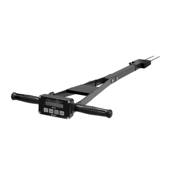
- Page 1 ® TDR 300 Soil Moisture Meter PRODUCT MANUAL Item # 6430FS...
-
Page 2: Table Of Contents
FieldScout TDR 300 Soil Moisture Meter. Please read this manual thoroughly before using your instrument. For customer support, or to place an order, call Spectrum Technologies, Inc. at (800) 248-8873 or (815) 436-4440 between 7:30 am and 5:30 p.m. CST FAX (815) 436-4460 e-mail: info@specmeters.com... -
Page 3: General Overview
General overview Thank you for purchasing the Field Scout TDR 300 Soil Moisture Meter. This manual describes the fea- tures and operation of the meter. Soil moisture is a critical and potentially highly vari- able component of the soil environment. Time-domain reflectometry is a proven technology for quickly and accurately determining volumetric water content (VWC) in soil. -
Page 4: Shaft Dimensions
Shaft dimensions The following are the dimensions of a fully extended shaft. It is possible to reduce the length of the meter by 2” (5cm) by adjusting the lower half of the shaft. 14” 4” Meter 16” 3.0” 3.1” 20” 1.3”... -
Page 5: Computer Interface/Changing Batteries
Computer Interface/ Changing Batteries Software Installation Insert the CD for Field Scout software into your PC’s disk drive. If auto-start is not enabled on your computer, select Run from the Start menu and type D:\Setup.exe (Substitute the appropriate drive letter for your CD drive). Click OK and follow the instructions on the screen. -
Page 6: Identifying The Correct Com Port
Identifying the Correct Com Port T h e c o m p u t e r Communications Port to which the PC-3.5 serial cable is connected can be identified by using a paper clip. 1. Disconnect the serial cable from the meter. 2. -
Page 7: Meter Operation
Meter Operation switch turns meter/ datalogger on and off. When the meter is turned on, it will display the battery status for 3 seconds. For the next 3 sec- onds, it will display how much logger memory has been used and, if the logger was enabled in the software, whether the GPS signal was found. - Page 8 Pressing the MODE button allows the user to determine the type of measure- MODE ment that will be taken or select the length of rods connected to the probe. Data Collection Modes Available measurement options are volumetric water con- MODE tent (VWC) using the standard or high clay mode (see p.
- Page 9 Meter Calibration Mode CALIBRATION MODE HIT READ To Cal Meter Calibration Screen This mode allows you to calibrate the meter. The cali- bration procedure is performed in air and distilled water (see Meter Calibration, p. 10). Requires firmware v. 6.5 or greater.
-
Page 10: Meter Calibration
Meter Calibration The meter has internal calibrations for standard and high-clay soil types. These calibrations will work for a large number of soils. However, each meter will have a small difference in how it responds to identical soil conditions. This is due to sensor drift or variability in the electronic components used during manufacturing. -
Page 11: Taking Readings
Taking Readings - Remove one of the hand screws from the shaft. This will allow you to unfold the shaft to its full length. Re- turn the screw to lock the shaft in the ex- tended position. - Screw the rods into the sockets at the bot- tom of the probe block. - Page 12 STNDRD VWC%=35.1 PL=S N015 A=36.3 Sample Data Screen Probe Length (Turf, Short, Medium, or Long rods) Number of readings included in the Average Average of all readings taken since meter was turned on or DELETE/CLR AVG button was pressed Note, the internal calibrations are valid for a wide range of mineral soils.
- Page 13 will not have a large affect on the reading but will de- crease the chances the rods will be bent or broken. Like- wise, it is best to avoid areas with rocks or other material that can cause the rods to deflect or bend. If the ground is especially hard or compact, you can use a Pilot Hole maker (item 6430PH) to make 1½”...
-
Page 14: Field Scout Software Toolbar
Field Scout software Toolbar Com Port The gray software cable con- nects the meter to the computer data port. Select the Com Port that is assigned to the computer data port. See Identifying the Correct Com Port (p. 6) for in- structions on how to determine which port to select. - Page 15 Download To download data from the internal data logger, turn the meter off and connect the gray serial cable to the RS-232 port on the underside of the meter. Click the Download button on the main software screen. In the Save Data As screen, give the file a descriptive name and select the loca- tion where it will be saved.
-
Page 16: Meter Settings
Meter Settings The Meter Settings screen in the Field Scout software is used to configure the meter and data logger for your specific application. The fields are described below. Meter Name: The name given the meter will be the title on the first line of the downloaded text file. Logger Settings: The data logger is enabled and dis- abled by checking the first box. - Page 17 rection is not found, only the soil moisture value will be stored in the data file. A time-zone correction should be entered in the third box. Units: When operating the meter in Relative Water Con- tent mode, the LCD can display the rod length options in English or metric units.
-
Page 18: Connecting To A Gps Unit
Connecting to a GPS Unit The data logger function must be enabled using the Field Scout software in order to record a GPS signal (see Meter Settings p. 16). The GPS unit must be plugged into the TDR 300 meter and running when the meter is first turned on. - Page 19 GPS unit. These components should be connected as shown in the figure below. Unit Meter Spectrum GPS computer GPS/DGPS interface cable Cable Connecting the TDR 300 meter to a GPS unit...
-
Page 20: Data Files
Data Files Sample data showing results of data collected with and without GPS activated. Note: GPS signal not found when recording data in lines 17 through 26. The data is stored in comma-delimited text files. These files can be opened with text-editing software (e.g. Micro- soft Word) or spreadsheet software (e.g. - Page 21 The data is separated into 6 fields: Latitude and Longitude (blank if a GPS unit was not connected), sample number, value, measurement type, and rod length. “measurement type” data field indicates whether the read- ing is volumetric water content, relative water content or measurement period.
-
Page 22: Volumetric Water Content Measurements
Volumetric Water Content Measurements Volumetric Water Content (VWC) The soil can be thought of as being composed of soil, water and air. The volumetric water content (VWC) is the ratio of the volume of water in a given volume of soil to the total soil volume. - Page 23 stant than air (ε = 1) or soil solids (ε = 3-7) is exploited to determine the VWC of the soil. The VWC measured by TDR is an average over the length of the waveguide. Electronics in the TDR 300 generate and sense the return of a high energy signal that travels down and back, through the soil, along the waveguide composed of the two replaceable, stainless steel rods.
-
Page 24: Relative Water Content
Relative water Content Mode RWC=25.5 D=3.17in A=23.4 N=06 Asnte In addition to displaying volumetric water content (VWC), the meter can also display the relative water content (RWC) and Water Deficit (see MODE button, p. 8). RWC is an index value calculated with respect to upper (wet) and lower (dry) VWC set points. - Page 25 The second line of the LCD gives the Average (A) of all readings taken, the Number (N) of readings taken and the 5-symbol name given to this soil type in the Meter Set- tings screen (see p. 16).
-
Page 26: Specifications
Specifications Measurement Percent volumetric water content Units Resolution 0.1% ±3.0% volumetric water content Accuracy –1 with electrical conductivity < 2 dS m 0% to saturation (Saturation is typically Range around 50% volumetric water.) Power 4 AAA alkaline batteries Approximately 12 month life Logger Capacity 2700 readings without GPS, 1250 read- ings with GPS/DGPS... -
Page 27: Appendix 1: Time Zone Corrections
Appendix 1 Time zone corrections Time Zone City Correction Dublin, Lisbon, London Rio de Janeiro, Montevideo Asuncion Atlanta, Indianapolis, New York, Ottawa, Bogota, Montreal, Toronto Guatemala City, Houston, New Orleans, Chicago, Mexico City, Winnipeg Phoenix, Denver, Edmonton San Francisco, Los Angeles, Vancouver Anchorage Honolulu Wellington... -
Page 28: Appendix 2 Soil-Specific Calibration
Appendix 2 Soil-Specific Calibration For maximum accuracy, you Period = 0950 uS may choose to perform a N015 soil-specific calibration rather than use either of the internal (Standard or High Clay) soil calibrations coded into the TDR 300’s firm- ware. In these cases, an independent soil moisture content measurement is required. - Page 29 VWC = 100*(M )/(ρ Where: mass (g) of wet and dry soil respectively wet, total soil volume (ml) ρ density of water (1g/ml) An alternate, but equivalent, calculation can be obtained from the gravimetric water content and soil bulk density. /ρ...
-
Page 30: Appendix 3: Troubleshooting
3. I am getting VWC values near 0% for all measurements, even in very wet soil. Most likely a circuit component in the display is damaged and must be repaired. Contact Spectrum Technologies or your dis- tributor to obtain a Return Goods Authorization (RGA) num- ber. - Page 31 This product is warranted to be free from defects in material or workmanship for one year from the date of purchase. During the warranty period Spectrum will, at its option, either repair or replace products that prove to be defective. This warranty does...
- Page 32 DECLARATION OF CONFORMITY Spectrum Technologies, Inc. 3600 Thayer Court Aurora, IL 60504 USA Model Numbers: 6430FS Description: Portable Soil Moisture Probe Type: Electrical Equipment for Measurement, Control, and Laboratory Directive: 2004/108/EC Standards: EN 61326-1:2006 EN 61000-4-2:1995, including A1:1998 and A2:2001 EN 61000-4-3:2002 As a consequence of the meter’s measurement principle, radio...
Need help?
Do you have a question about the fieldscout TDR 300 and is the answer not in the manual?
Questions and answers