Table of Contents
Advertisement
Advertisement
Table of Contents

Summary of Contents for Lovibond SensoDirect 150
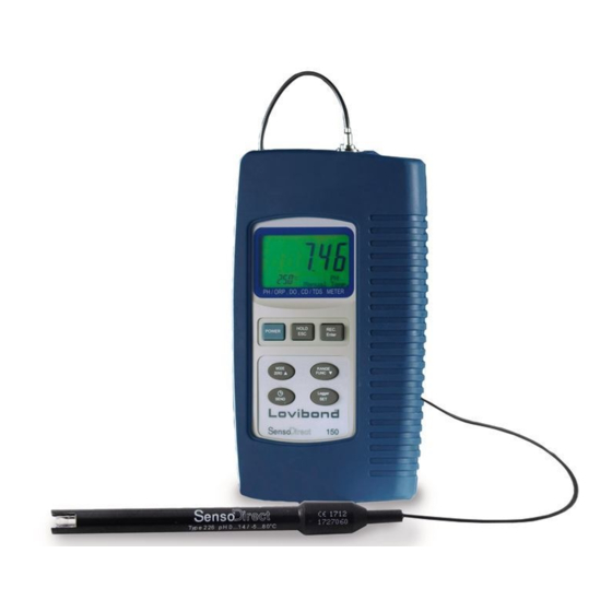
- Page 1 SensoDirect 150 MultiMeter Instrument - Instruction Manual pH/ORP CD/TDS...
-
Page 2: Table Of Contents
Table of Contents Specifications .................. 1 1.1 General Specifications ..............1 1.2 Electrical Specifications ..............2 Front Panel Description ..............5 pH/mV Measuring and Calibration Procedure ..................7 Conductivity/TDS Measuring and Calibration Procedure ..............13 DO (Dissolved Oxygen) Measuring and Calibration Procedure ............18 Data Load, Data Record, Data Logger ........ -
Page 3: Specifications
1. Specifications 1.1 General Specifications Circuit Custom microprocessor LSI Display LCD size : 58 mm x 34 mm. Measurement pH / Oxidation Reduction Potential (ORP) Conductivity/Total Dissolved Solids (TDS) Dissolved Oxygen (DO) Temperature Sampling Time of Data Log- 1 second to 8 hours 59 minutes and 59 seconds Data Hold Freeze the display reading. -
Page 4: Electrical Specifications
Weight • instrument 390 g (batteries included) • with protective covering 620 g Dimension • instrument: 203 x 76 x 38 mm • with protective covering: approx. 220 x 125 x 45 mm 1.2 Electrical Specifications (23± 5°C) A. pH/mV Measurement 0 to 14 pH -1999 mV to 1999 mV Input Impedance Temperature Compensation Manual 0 to 100°C for pH measurement (32 to 212°F) Automatic (ATC) 0 to 65°C (32 to 149 °F) with tem-... - Page 5 B. Conductivity Conductivity probe Carbon rod electrode for long life Function • Conduction (µS, mS) • Total Dissolved Solids (ppm) • Temperature (°C, °F) Temperature Compensation Automatic from 0 to 60°C (32 – 140 °F), with temperature compensa- tion factor variable between 0 to 5 % per °C Probe Operating Temperature 0 to 60 °C (32 to 140°F) Probe Dimension Round, 22 mm diameter x 120 mm length Probe Weight approx. 65 g...
- Page 6 C. TDS (Total Dissolved Solids) Range Measurement Resolution Accuracy 200 ppm 0 to 132 ppm 0.1 ppm ± (2 % F.S. + 1 digit) 2,000 ppm 132 to 1,320 ppm 1 ppm 20,000 ppm 1,320 to 13,200 ppm 10 ppm 200,000 ppm 13,200 to 132,000 ppm 100 ppm F.S. = Full Scale D.
-
Page 7: Front Panel Description
2. Front Panel Description (Fig. A) A-15 A-14 A-13 A-16 A-12 A-11 A-10 A-1 Display A-2 Power Button A-3 REC Button (Enter Button) A-4 HOLD Button (ESC Button) A-5 Mode Button ( Up Button, Zero Button) A-6 Function Button (Range Button, Down Button) A-7 Send Button (Clock Button) A-8 SET Button (Logger Button) - Page 8 DC IN RS232 RESET A-17 A-18 A-19 A-20 A-17 DC 9V Power Adapter Input Socket A-18 RS-232 Output Terminal A-19 System Reset Button A-20 LCD Brightness Adjust Attention: Please do not put more than one electrode only into the water sample when using an instrument that works with various electrodes.
-
Page 9: Ph/Mv Measuring And Calibration Procedure
3. pH/mV Measuring and Calibration Procedure The meter default settings are as follows: • The display unit is set to pH. • The temperature unit is set to °C. • Manual temperature setting (without ATC probe connection) • Auto power off. •... - Page 10 Fig. B 3.1 pH measurement (with manual temperature setting) 1) Attach the pH Electrode by installing the “Probe Plug“ (Fig. B-1) into the “pH Socket/BNC Socket“ (Page 5, Fig. A-16). 2) Power on the meter by pressing the “Power” button once. 3) Keep pressing the “Mode” button until the display of bottom right shows “pH“ and “Manual Temp.“ indicator. 4) Adjust the Manual Temp. value exactly to the same temperature as the solution. For procedure refer to chapter 7.7, page 28. 5) Remove cap and hold the pH Electrode body (Fig. B-2) and com- pletely immerse the “Sensing Head“ (Fig. B-3) in the solution to be measured and gently swirl the probe. 6) The upper display will show the pH value, the bottom left display will show the Manual Temp.
- Page 11 3.2 pH measurement (with ATC , automatic Temperature Compensation) 1) All the procedures are the same as for 3.1 “pH measurement (manual temperature setting)“, except for attachment of a temperature probe by inserting the plug of the temperature probe into the “Temp. Socket“ (Page 5, Fig. A-13), and immers- ing the sensing head of the temperature probe into the measure- ment solution. 2) The upper display will show the pH value, the bottom left display will show the Temp. value of the measured solution, and the bottom right display will show “Auto Temp.“ as example below: 7.01 25.0 °C Auto Temp. When not in use the “Electrode Sensing Head“ (Page 8, Fig. B-3) should always be immersed in water by part-filling the probe cap, (Page 8, Fig.
- Page 12 Press the “Function” button once so that the bottom right display shows “mV“ . 4) The upper display will show the mV value. 3.4 pH calibration Calibration - Introduction An “ideal” pH Electrode generates 0 mV at pH 7.00 (177.4 mV at pH 4). The meter has been calibrated with signals which simulate the “ideal” pH Electrode (based on 25°C ambient environment). However not every pH Electrode is as accurate as the “ideal” one, so calibration procedures are necessary before first time measure- ment. In addition to calibration before first time measurement, us- ers are also recommended to carry out regular calibration to ensure high accuracy measurements. Required Equipment for Calibration 1) pH Electrode. 2) pH buffer solutions. Calibration Procedure 1) Attach the pH Electrode by installing the “Probe Plug“ (Page 8, Fig. B-1) into the “pH Socket/BNC Socket“ (Page 5, Fig. A-16).
- Page 13 5) Press the “REC” button and “HOLD” button at the same time. The display will show the following screen as an example. Now release. 7.00 PH CAL. 23.5 °C ^, v Enter : Y 6) • If the buffer solution is pH 7.0 (± 1 pH), the upper display will show 7.00 automatically. • If the buffer solution is pH 4.0 (± 1 pH), the upper display will show 4.00 automatically. • If the buffer solution is pH 10.0 (± 1 pH), the upper display will show 10.00 automatically. • If the buffer solution value is beyond pH 7.00, pH 4.00, pH 10.00 (for example 7.01, 4.02, 10.03) then use “ ” button, “ ” button to adjust the display value to exactly match the pH buffer solution value. 7) Press the “Enter” button twice to save the calibration data and finish the calibration procedure. 8) The described procedure can be performed for the following calibration points: pH7 calibration pH4 calibration pH10 calibration...
- Page 14 • Repeat the above calibration procedures at least twice to ensure accuracy. 3.5 ORP calibration 1) Attach the ORP electrode (optional, ORP-14) by connecting the ORP electrode to the meter. 2) Power on the meter, and set the mode and function to “mV“ (refer to chapter 3.3, Page 9). 3) Immerse the sensing head of the ORP electrode in the ORP standard buffer solution. The upper display will show the ORP value in mV. 4) Press the “REC” button and “HOLD” button at the same time. The display will show the following screen as an example. Now release. Adjust 5) Use “ ” button, “ ” button to adjust the upper display value to exactly match the ORP buffer solution value. Press the “Enter” button twice to save the calibration data and finish the calibra- tion procedure. • ORP calibration is only possible if the ORP buffer solution value is >...
-
Page 15: Conductivity/Tds Measuring And Calibration Procedure
4. Conductivity/TDS Measuring and Calibration Procedure The meter default settings are as follows: • The display unit is set to conductivity (µS, mS). • The temperature unit is set to °C. • Temp. compensation factor is set to 2.0% per °C. • Auto range. • Auto power off. • Data logger function sampling time: 2 seconds. Measurement Value Display layout 19.00 200.0 µS 24.2 °C Auto Range Temp. value Temp unit Range Auto or Manual scale range... - Page 16 Fig. C 4.1 µS, mS measurement 1) Attach the Conductivity Probe by installing the “Probe Plug“ (Fig. C-1) into the “CD Socket“ (Page 5, Fig. A-14). 2) Power on the meter by pressing “Power” button once. 3) Keep pressing the “Mode” button until the bottom right display shows a value (e.g. “200 mS“) and “Auto Range“. 4) Remove probe cap and hold the probe body (Fig. C-2) and com- pletely immerse the “Sensing Head“ (Fig. C-3) in the solution to be measured. Swirl the probe to let any air bubble escape from the sensing head. 5) The display will show the conductivity values in either “mS / cm” or “µS / cm”. At the same time the bottom left display will show the Temp. value of the measured solution.
- Page 17 Manual range operation The meter default is set to auto range mode. Under auto range measurement, the bottom right display will show the “Auto Range“ indicator. If manual range mode is required, the procedures are as follows: 1) Press the “Range” button continuously for at least two seconds until the bottom right display shows the “Manual Range“ indica- tor. Release the “Range” button. Now the meter is set for manual range operation. 2) Press the “Range” button once to change the range. The range (200 µS, 2 mS, 20 mS, 200 mS) will show under the measure- ment value. ---- 3) • If the display shows “ “, it indicates an overrange. Select the next, higher range. • If the display shows “ ---- “, it indicates an underrange. Select the next, lower range.
- Page 18 4.2 TDS (ppm) measurement Measuring procedures are the same as above 4.1 Conductivity (µS, mS) measurement, except for changing the display unit from µS, mS to ppm. For detailed procedures please refer to page 29, chap- ter 7.9 CD (µS, mS), TDS (ppm) Setting. 4.3 Calibration 1) Obtain a the standard conductivity solution: For example : • 2 mS range calibration solution : 1.413 mS Conductivity Standard Solution • 200 µS range calibration solution : 80 µS Conductivity Standard Solution • 20 mS range calibration solution : 12.88 mS Conductivity Standard Solution or other Conductivity Standard Solution 2) Install the “Probe Plug“ (Page 14 Fig. C-1 ) into the “CD Socket“...
- Page 19 6) Use “ ” button (Page 5, Fig. A-5), “ ” button to adjust the upper display value to match the standard conductivity value. 7) Press the “Enter” button twice to save the calibration data, and finish the calibration procedure. • If only one calibration point is needed, just set the 2 mS range (1.413 mS Cal.). • A multi-point calibration procedure should always start with 2 mS range (1.413 mS Cal.), then proceed to other ranges (20 µS range, 20 mS range or 200 mS range) if necessary.
-
Page 20: Do (Dissolved Oxygen) Measuring And Calibration Procedure
5. DO (Dissolved Oxygen) Measuring and Calibration Procedure ATTENTION: Make sure the Oxygen probe is filled with Elec- trolyte! To fill the Probe‘s Electrolyte, refer to chapter 5.3 “Probe maintenance“, page 22. The meter default settings are as follows: • The display unit is set to % O • The temperature unit is set to °C. - Page 21 5.1 Dissolved Oxygen measurement Fig. D 1) Attach the Oxygen Probe by installing the “Probe Plug“ (Fig. D-1) into the “DO Socket“ (Page 5, Fig. A-15). 2) Power on the meter by pressing the “Power” button once. 3) Keep pressing the “Mode” button until the bottom rigth display shows “%O “. CAUTION! Ensure calibration on air before measurement. Wait approx. 2 minute until the reading value stabilises. If the reading value on air is not within 20.7 to 21.1 (20.9 ±...
- Page 22 5) • Remove the protective cover from the probe head and immerse the probe to a depth of at least 10 cm in the meas- ured liquid in order for the automatic temperature compensa- tion to take effect. • Thermal equilibrium must occur between the probe & the measurement sample, which usually takes to a few minutes if the Temp. difference between the two is only a few degrees Celsius. • To measure the dissolved oxygen content in any given liquid, it is sufficient to immerse the tip of the probe in the solution, making sure that the velocity of the liquid coming into contact with the probe is at least 0.2 - 0.3 m/s. This is achieved by swirling the probe in the solution. • During laboratory measurements, the use of a magnetic stirrer/ agitator is recommended. In this way, errors due to air diffusion in the solution are reduced to a minimum. 6) The display will show the Dissolved Oxygen values (mg/L). At the same time, the bottom left display will show the Temp. value of the measured solution. 7) Rinse the probe carefully with normal tap water after each series of measurements. Oxygen in the air When the display unit shows “%O “, this represents an approxi- mate air Oxygen value.
- Page 23 “Height“ (Altitude) compensation value adjustment To change the Height compensation value, please refer to page 29, chapter 7.11 (Height Compensation value Setting). 5.2 Calibration 1) Install the “Probe Plug“ (Page 19, Fig. D-1) into the “DO Socket“ (Page 5, Fig. A-15). 2) Power on the meter by pressing the “Power” button once. 3) Keep pressing the “Mode” button until the bottom right display shows “%O “. Wait for at least 5 minutes until the display reading values stabilise with no fluctuation. 4) Press the “REC” button and “HOLD” button at the same time. The display will show the following screen, as an example. Now release. 20.9 O2 CAL. ESC:N ENTER: Y 23.5 °C 5) Press the “Enter” button twice. This will save the calibration data and finish the calibration procedure. Finally the lower display will show “O2 CAL. OK“. Return to the normal screen.
- Page 24 5.3 DO Probe maintenance a) First time use of the meter: To keep the DO probe in the best condition, be sure to fill the Oxygen Probe, with Electrolyte prior to first use. b) After using the probe for a certain period: If the user cannot calibrate the meter properly or the meter‘s readings are not stable, please check the oxygen probe to see if the electrolyte in the probe head container has run out or the diaphragm (inside the probe head) has a problem (e.g. is dirty). If yes, please fill the electrolyte or change the diaphragm set. Then re-calibrate. Diaphragm (probe head including diaphragm set): A key component of the oxygen probe is the thin Teflon diaphragm housed in the tip of the probe. This diaphragm is permeable by oxygen molecules but not by the considerably larger molecules contained in the electrolyte. Accordingly oxygen may diffuse throughout the electrolyte solution contained in the probe, and its concentration may be quantified by the measurement circuit. This sensitive diaphragm is rather delicate and is easily damaged if it comes into contact with solid objects or is subjected to knocks. If the diaphragm is damaged or the electrolyte has run out, please see...
- Page 25 Probe Electrolyte Probe head including Diaphragm set 1) Unscrew the “Probe Head“ (Page 23, Fig E-3). 2) Pour out the old Electrolyte from the container in the “Probe head“. Fig. E 3) Fill the container with new Electrolyte. 4) Screw the probe head (Fig E-3) back onto the E-1 probe body. 5) When not in use, insert the probe head into the probe protection cover (Page 19, Fig. D-5) that is E-2 equipped with a wet sponge. E-3 E-1 Probe body E-2 Temp. sensor E-3 Probe head...
-
Page 26: Data Load, Data Record, Data Logger
6. Data Load, Data Record, Data Logger 6.1 Data Hold During the measurement, press the “Hold” button once to hold the measured value and the LCD will display a “HOLD“ symbol. Press the “Hold” button once again to release the data hold function. 6.2 Data Record (MAX, MIN reading) 1) The data record function records the maximum and minimum readings. Press the “REC” button once to start the Data Record function and a “REC“ symbol will be displayed. 2) With the “REC“ symbol on the display: a) Press the “REC” button once more. The “REC MAX“ symbol along with the maximum value will appear on the display. To delete the maximum value, just press the “Hold” button once. - Page 27 The data logger procedure is as follows: a) Pushing the “Logger” button once will show the sampling time value on the bottom left display then disappeared. b) Press the “REC” button once to start the Data Record function and a “REC“ symbol will be displayed. c) Auto Data Logger The Sampling frequency can be set from 1sec to 8h 59min 59sec (refer to chapter 7.4 page 27). E.g.: If a sampling frequency of 1 min is set, the meter stores the measured value every minute 25.5°C 2.000 mS AutoRange until the data logger function is stopped. Press the “Logger” button once to start the Auto Data Logger function, at the same the bottom right REC DATA...
-
Page 28: Advanced Adjustment Procedure
7. Advanced Adjustment Procedures Before carrying out the following Advanced Adjustment Procedures exit the “Hold function“ and the “Record function“ first. The dis- play will not show the “HOLD“ and the “REC“ marker. 1) Press the “SET” button for at least two seconds until the lower display shows: XXXXX Memory Space Push the “ESC” button to return to the normal measuring display. 2) To select “Advanced Setting Function”, press and hold the SET button, then press again to successively show the following: 7.1 Memory Space 7.2 Clear Memory 7.3 Date/Time Set 7.4 Sample Time 7.5 Auto Power Off 7.6 Temp. Unit The following functions appear only if the corresponding measure- ment function is selected (pH, CD, DO) 7.7 M. TEMP. SET (pH mode) 7.8 Temp. Comp. (CD mode) 7.9 CD, TDS Select (CD mode) 7.10 % Salt SET (DO Mode) 7.11 Height Value (DO Mode) -
Page 29: Check Memory Space
3) To make advanced Adjustments, use the following buttons: “ESC”, “Enter”, “ ” Up, “ ” Down, “SET”. 7.1 Check Memory Space To check the free memory, press and hold the SET button for at least 2 seconds. The display will show. XXXXX Memory Space XXXXX is the free memory balance. For example XXXXX=15417. 7.2 Clear Memory To delete readings from the memory: • Push ENTER button twice to confirm. • Press the ESC button once to quit, and return to the main measurement display. 7.3 Date/Time Setting • Use “ ” Up, “ ” Down and “Enter” (->) to set the Date (year- month-date) and the Time (hour-min-sec). -
Page 30: Auto Power Off Default Setting
7.5 Auto Power Off Default Setting • Use “ ” Up, “ ” Down to select “ 1 “ or “ 0 “. 1 = Auto power On. 0 = Auto power Off. • After Auto Power Off adjustment, push the “Enter” button, then press “ESC” to save the data and return to the normal display. 7.6 Temp. Unit Default Setting • Use “ ” Up, “ ” Down to select “1“ or “0“ . 1 = °F 0 = °C • After adjusting the Temperature unit, push the “Enter” button, then press “ESC” to save the data and return to the normal display. 7.7 pH Manual Temp. Setting • This procedure is only to adjust the manual temperature compensation value for pH measurement. • The lower display will show: M. TEMP. SET ^, v Enter:Y... -
Page 31: Cd ( Μs, Ms ), Tds ( Ppm ) Setting
• After setting the desired value, press “Enter“, then press “ESC” to save the data and return to the normal display. • Temp. Compensation Factor is typically set to 2.0% per C degree. 7.9 CD (µS, mS), TDS (ppm) Default Setting • This procedure is only used for the Conductivity function. • Use “ ” Up, “ ” Down to select “1“ or “0“. 0 = µS, mS 1 = ppm • After adjusting the unit (µS/mS, ppm), press “Enter”, then press “ESC” to save the data and return to the normal display. 7.10 DO % Salt Compensation Value Setting • This procedure is only available for the DO function. • The lower display will show: % Salt SET ^,v Enter:Y... -
Page 32: Do Height (Altitude) Compensation Value Setting
7.11 DO Height (Altitude) Compensation Value Setting • This procedure is only for the DO function. • The lower display will show: 0 = meter 1 = ft (foot) FT= foot 1 Foot = 0.3048 m • Use “ ” Up, “ ” Down to select “0“ or “1“. • Press “Enter” once, and the lower display will show: Height Value Meter • Use “ ” Up, “ ” Down to select the desired Height value. • Press “Enter” once, then press “ESC” to save the data and return to the normal display. • Typical setting is 0 meter (0 feet). -
Page 33: Data Output
8. Data Output From The Meter To send data out from the meter, exit the “Hold function“ and the “Record function“ first. The display will not show “HOLD“ and “REC“ markers. 1) Press and hold the “SEND” button for at least 2 seconds until the bottom right display shows “Transmit mode“, then release the button. The display will show the following screen alternately: 158.4 µS µS Transmit mode Transmit mode xx:xx:xx Block no. Start data address First data in Start time of of each block each block each block Use “... - Page 34 Block 1 Data 1 Data X Block 2 Data X+1 Data Y ........Block 250 Data Z Data 16,000 3) Once the desired Memory Block no. has been selected, push the “Send” button once, and the data in the Memory Block will transmit. During data output, the bottom right display will show “Sending Data!“. When data output is completed, the bottom right display will show “Transmit mode“ again. 4) Push “ESC” button to exit the data output function and return to the normal display. Remarks : • To transmit the data to a computer, connect an RS232 cable or USB cable, and start the Data Logger software. •...
-
Page 35: Rs232 Pc Serial Interface
9. RS232 PC-Serial Interface The instrument has an RS232 PC serial interface via the RS-232 Out Terminal“ (Page 6, Fig. A-18) . Data output is via a 16 digit stream which can be downloaded to user‘s specific application. An RS232 lead with the following con- nection will be required to link the instrument to the PC serial port: Meter PC (3.5 mm jack plug) (9W ‚D “ Connector) Center Pin......Pin 4 Ground/shield....Pin 2 2.2 K resister Pin 5 The 16 digit data stream will be displayed in the following format : D15 D14 D13 D12 D11 D10 D9 D8 D7 D6 D5 D4 D3 D2 D1 D0... - Page 36 Each digit indicates the following status: D15 Start Word = 02 Sending upper display data = 1 Sending lower display data = 2 D12, D11 Annunciator for Display µS = 13 mS = 14 ppm = 19 pH = 05 mV = 18 mg/L = 07 % O2 = 06 Polarity 0 = Positive 1 = Negative Decimal Point (DP) position from right to left 0 = No DP, 1= 1 DP, 2 = 2 DP, 3 = 3 DP D8 to D1 Display reading, D1 = LSD, D8 = MSD For example:...
-
Page 37: Battery Replacement
10. Battery Replacement 1) When the left corner of the display shows “ “, it is necessary to replace the batteries (4x mignon size type AA 1.5V). 2) Unscrew the single retaining screw, and then slide open the “Battery Cover“ (Page 5, Fig. A-10) and remove the batteries. 3) Replace with new batteries and slide on the cover. Replace the retaining screw. 4) Make sure the battery cover is tightly secured after changing the batteries. 11. System Reset If the meter experiences problems, such as: CPU system is garbled (for example, the key button cannot be operated..). Then system RESET will fix the problem. The system RESET proce- dure is as follows: Use a pin tool to push the “System Reset Button“ (Page 6, Fig. A-19). Then press “Power” on again to fix the problem. -
Page 38: Optional Accessories
12. OPTIONAL ACCESSORIES RS232 cable • Computer interface cable. UPCB-02 • Used to connect the meter to a computer (COM port). USB cable • Computer interface cable. Data Logger • Software used to download data from software the data logger (data recorder) to a SW-DL2005 computer. Data Acquisition • The SW-U801-WIN is a powerful multi Software software display (1/2/4/6/8 displays) SW-U801-WIN application, providing the functions of data logging, text display, angular display, chart display, data recorder high/low limit, data query, text report, chart report. An .xxx.mdb data file can be retrieved for EXCEL, ACCESS.., and other intelligent applications. Power adapter AC 110V to DC 9V. - Page 39 Accessories for conductivity Conductivity probe Calibration solution 1413 µS/cm, 500 ml, traceable to N.I.S.T Accessories for oxygen Oxygen sensor Spare membrane for oxygen sensor Spare electrolyte for oxygen sensor Accessories Temperature probe PT1000 RS232 cable USB cable Data logger software Data acquisition software Power supply Case incl. foam for SensoDirect 150...
- Page 40 Tintometer GmbH The Tintometer Limited Lovibond Water Testing Lovibond House, Solar Way ® Schleefstraße 8-12 Solstice Park, Amesbury, SP4 7SZ 44287 Dortmund Tel.: +44 (0)8452 264654 Tel.: +49 (0)231/94510-0 Fax: +44 (0)1980 625412 Fax: +49 (0)231/94510-20 water.sales@tintometer.com www.tintometer.com sales@tintometer.de www.tintometer.de...
Need help?
Do you have a question about the SensoDirect 150 and is the answer not in the manual?
Questions and answers