
Related Manuals for BOXLIGHT ProColor Series


Summary of Contents for BOXLIGHT ProColor Series
- Page 1 ProColor 551, 651H, 701H, 651U, 751U, 841U ProColor Series1 Service Manual mimio.boxlight.com...
- Page 2 mimio.boxlight.com...
-
Page 3: Table Of Contents
Table of Contents Safety Considerations Product Photos System Block Design Internal Photo Key Parts List Disassembly Guide Removing Circuit Boards Internal Cabling Touch Frame Windows PC Option PCB Details and Measurements Main Board TV Power Board Keys Board USB Board MCU Board Touch Frame... -
Page 4: Safety Considerations
• Please disconnect the power cable, remote communication system, network, modem, and other devices before opening the screen, unless otherwise specified in the instal- lation and configuration process • Disconnect all cables if the display is to be installed, uninstalled, moved or opened mimio.boxlight.com... -
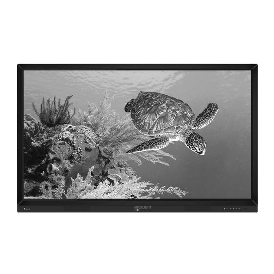
Page 5: Product Photos
Front and Rear Views Front view Rear view... - Page 6 Side View and Connector Panels mimio.boxlight.com...
-
Page 7: System Block Design
System Block Diagram... -
Page 8: Internal Photo
Internal View from Back MCU Board TV Main TV Power Pink Piece of Paper T-CON Keys and IR Board USB Board mimio.boxlight.com... -
Page 9: Key Parts List
Key Parts List... -
Page 10: Disassembly Guide
Disassembly Guide mimio.boxlight.com... - Page 11 Disassembly - Screw TorqueReference Table...
- Page 12 • Remove all the screws shown above - it is recommended to sort them into separate tem- porary storage containers • The shells can now be removed IMPORTANT - when replacing the shells the correct screws must go into the associated socket and the recommended torque level must be applied. Otherwise, damage may occur. mimio.boxlight.com...
-
Page 13: Removing Circuit Boards
Removing Circuit Boards Note screw locations below that attach the boards to the chassis TV Main Board T.MS6369.71L... - Page 14 Removing Circuit Boards TV Power Board MCU Board Key Board, IR Board & Speaker mimio.boxlight.com...
- Page 15 Removing Circuit Boards USB Board To replace any circuit board: • Disconnect from AC power • Disconnect all cables • Remove the shell covers (see prior instructions) • Remove the lower terminal block, side terminal block, and wires IMPORTANT - when replacing the shells the correct screws must go into the associated socket and the recommended torque level must be applied.
-
Page 16: Internal Cabling
Note: it is the nature of the manufacturing process that there may be some differences between the cable layouts shown in this document and those encountered in actual units. Therefrore, the following diagrams are provided as general reference rather than as specific instruction. mimio.boxlight.com... - Page 17 Internal Cabling HDMI Cable MCU Board TV Power TV Main...
- Page 18 Internal Cabling Touch Cable TV Main LDVS Cable T-Con mimio.boxlight.com...
- Page 19 Internal Cabling Speaker Cable T-Con TV Main Relay Control Cable MCU Board TV Power TV Main...
- Page 20 Internal Cabling Relay Control Cable Continued Keys and IR Cable MCU Board TV Power TV Main mimio.boxlight.com...
- Page 21 Internal Cabling Keys and IR Cable Continued PC Signal Cable...
- Page 22 Audio Amplifier Power Supply Cable TV Power TV Main T-Conn Main TV Power TV Main mimio.boxlight.com...
- Page 23 Main Board Power Supply Cable TV Power TV Main...
- Page 24 • When replacing the cable be sure to use the cable clips and adhesive tape • Verify that all cables have been returned to their respective positions and are properly seated. • Replace the shell covers while being careful to install the correct type of screw to the matching socket. mimio.boxlight.com...
-
Page 25: Touch Frame
Touch Frame Touch Frame Disassembly • Disconnect the display from AC power • Disconnect all cables from the display • Remove the thumbscrew at the rear of each of the four corners Thumb Screw • Remove the four corner pieces of the frame from the front •... -
Page 26: Windows Pc Option
Optional Internal Windows PC Front View Front View mimio.boxlight.com... - Page 27 Optional Internal Windows PC Internal View...
-
Page 28: Pcb Details And Measurements
Main Board mimio.boxlight.com... - Page 29 Main Board...
- Page 30 Main Board mimio.boxlight.com...
- Page 31 Main Board...
- Page 32 Main Board mimio.boxlight.com...
- Page 33 Main Board...
- Page 34 Main Board mimio.boxlight.com...
-
Page 35: Tv Power Board
TV Power Board Con2 - Main Power... - Page 36 TV Power Board mimio.boxlight.com...
-
Page 37: Keys Board
Keys Board... -
Page 38: Usb Board
USB Board mimio.boxlight.com... -
Page 39: Mcu Board
MCU Board... - Page 40 MCU Board mimio.boxlight.com...
- Page 41 MCU Board...
- Page 42 MCU Board MCU Board mimio.boxlight.com...
-
Page 43: Touch Frame
Touch Frame Touch Frame Front View of Main Touch Board Back View of Main Touch Board Detail View of Cable Connector of Main Touch Board Touch Board Pin Definition... - Page 44 mimio.boxlight.com...
Need help?
Do you have a question about the ProColor Series and is the answer not in the manual?
Questions and answers