Table of Contents
Advertisement
Advertisement
Chapters
Table of Contents
Troubleshooting

Related Manuals for Hypertherm powermax600


Summary of Contents for Hypertherm powermax600
- Page 1 powermax ® Plasma Arc Cutting System Service Manual 803400 Revision 2...
- Page 2 (P/N 803400) Revision 2 - NOVEMBER 1999 Hypertherm, Inc. Hanover, NH USA http://www.hypertherm.com email:info@hypertherm.com © Copyright 1999 Hypertherm, Inc. All Rights Reserved Hypertherm and Powermax are trademarks of Hypertherm, Inc. and may be registered in the United States and/or other countries.
- Page 3 Hypertherm Offices Worldwide : Hypertherm, Inc. Etna Road, P.O. Box 5010 Hanover, NH 03755 USA Tel.: (603) 643-3441 (Main Office) Fax: (603) 643-5352 (All Departments) Tel.: (800) 643-9878 (Technical Service) Tel.: (800) 737-2978 (Customer Service) email: info@hypertherm.com (General Information) email: service@hypertherm.com (Technical/Customer Services)
-
Page 4: Electromagnetic Compatibility
LECTROMAGNETIC OMPATIBILITY EMC INTRODUCTION e. Health of the people around, for Cutting Cables example the use of pacemakers and The cutting cables should be kept as The CE power supplies have been built in hearing aids. short as possible and should be compliance with standard EN50199. -
Page 5: Warranty
Hypertherm's specifica- carrier. Hypertherm will furnish you with a copy of the bill of tions, and in cases of designs, processes, formulae or lading upon request. If you need additional assistance, call... -
Page 6: Table Of Contents
ABLE OF ONTENTS Electromagnetic Compatibility ..........................i Warranty ................................ii SECTION 1 - SAFETY RECOGNIZE SAFETY INFORMATION ....................... 1-2 FOLLOW SAFETY INSTRUCTIONS ........................1-2 CUTTING CAN CAUSE FIRE OR EXPLOSION ....................1-2 ELECTRIC SHOCK CAN KILL ..........................1-3 CUTTING CAN PRODUCE TOXIC FUMES ......................1-3 PLASMA ARC CAN CAUSE INJURY AND BURNS .................... - Page 7 POWER SUPPLY – BACK INTERIOR RIGHT SIDE .................... 4-4 POWER SUPPLY – INTERIOR FAN SIDE ......................4-5 POWER SUPPLY – HEAT SINK ASSEMBLY ....................... 4-6 RECOMMENDED SPARE PARTS - POWERMAX600- 230/400V ............... 4-7 SECTION 5 PARTS LIST - 208-240/480V POWER SUPPLY – EXTERIOR ........................... 5-2 POWER SUPPLY –...
- Page 8 Grounding Safety ....................1-4 Compressed Gas Equipment Safety ..............1-5 Gas Cylinders Can Explode if Damaged ..............1-5 Noise Can Damage Hearing .................. 1-5 Pacemaker and Hearing Aid Operation ..............1-5 Additional Safety Information ................. 1-5 Warning Label ......................1-6 Hypertherm Plasma Systems...
-
Page 9: Recognize Safety Information
Do not cut pressurized cylinders, pipes, or any table to eliminate the possibility of hydrogen deto- closed container. nation. Refer to the Appendix section of this manual • Do not cut containers that have held combustible for aeration manifold details. materials. Hypertherm Plasma Systems 11-98... -
Page 10: Electric Shock Can Kill
• Provide a disconnect switch close to the power grounding conductor first. supply with properly sized fuses. This switch allows • Each Hypertherm plasma system is designed to be the operator to turn off the power supply quickly in an used only with specific Hypertherm torches. Do not emergency situation. -
Page 11: Plasma Arc Can Cause Injury And Burns
Fasten the retaining nut tightly. Work Table Connect the work table to an earth • Tighten all electrical connections to avoid excessive ground, in accordance with appropriate national or local heating. electrical codes. Hypertherm Plasma Systems 4-99... -
Page 12: Compressed Gas Equipment Safety
Protection Association, 470 Atlantic Avenue, Boston, MA 02210 Hazardous Substances , American Welding Society 10. OSHA, Safety and Health Standards , 29FR 1910 550 LeJeune Road, P.O. Box 351040, Miami, FL 33135 U.S. Government Printing Office, Washington, D.C. 20402 Hypertherm Plasma Systems 11-98... -
Page 13: Warning Label
Use welding helmet with correct shade of filter. Wear complete body protection. Become trained and read the instructions before working on the machine or cutting. Do not remove or paint over (cover) warning labels. Hypertherm Plasma Systems 8-99... - Page 14 SÉCURITÉ DES BOUTEILLES DE GAZ COMPRIMÉ ........1a-5 LES BOUTEILLES DE GAZ COMPRIMÉ PEUVENT EXPLOSER EN CAS DE DOMMAGES ....................1a-5 LE BRUIT PEUT PROVOQUER DES PROBLÈMES AUDITIFS ..... 1a-5 PACEMAKERS ET PROTHÈSES AUDITIVES ..........1a-5 ÉTIQUETTE DE SÉCURITÉ ................1a-6 HYPERTHERM Systèmes plasma 1a-1 08/99...
-
Page 15: Identifier Les Consignes De Sécurité
Se référer à l’annexe du manuel pour plus de • Ne pas couper de récipients contenant des matières renseignements sur les collecteurs d’aération. combustibles. 1a-2 HYPERTHERM Systèmes plasma 08/99... -
Page 16: Les Chocs Électriques Peuvent Être Fatals
• Installer un sectionneur avec fusibles appropriés, à la prise de terre appropriée. proximité de la source de courant. Ce dispositif permet à • Chaque système plasma Hypertherm est conçu pour être l’opérateur d’arrêter rapidement la source de courant en utilisé uniquement avec des torches Hypertherm cas d’urgence. -
Page 17: L'arc Plasma Peut Provoquer Des Blessures Ou Des Brûlures
Bien serrer l’écrou de retenue. Table de travail Raccorder la table de travail à la terre, • S’assurer que toutes les connexions sont bien serrées conformément aux codes de sécurité locaux ou nationaux pour éviter la surchauffe. appropriés. 1a-4 HYPERTHERM Systèmes plasma 08/99... -
Page 18: Sécurité Des Bouteilles De Gaz Comprimé
• Faire passer le faisceau de la torche le plus près possible du câble de retour. • Ne pas s’enrouler le faisceau de la torche ou le câble de retour autour du corps. • Se tenir le plus loin possible de la source de courant. HYPERTHERM Systèmes plasma 1a-5 08/99... -
Page 19: Étiquette De Sécurité
Porter des vêtements protecteurs couvrant la totalité du corps. Se former à la technique du coupage et lire les instructions avant de manipuler l’équipement ou de procéder au coupage. Ne pas retirer ou peindre (recouvrir) les étiquettes de sécurité. 1a-6 HYPERTHERM Systèmes plasma 08/99... - Page 20 PECIFICATIONS Section 2 SPECIFICATIONS In this section: SPECIFICATIONS, POWER SUPPLY ..............2-2 SPECIFICATIONS, PAC123 TORCHES ..............2-3 SETUP SPECIFICATIONS..................2-4 INSTALL POWER CORD PLUG ................2-4 CHECK REQUIRED INPUT VOLTAGE ..............2-4 S MARK (230/400 VOLT ONLY) ................2-4 GROUNDING REQUIREMENTS ................2-5 POWER CORD / EXTENSION CORD ..............
-
Page 21: Section 2 Specifications
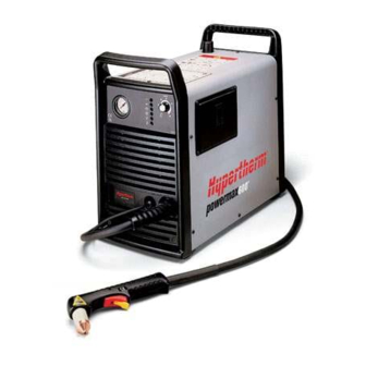
° 0 ° 0 ° 0 ° 4 ° 4 y t i f - l c i f Powermax600 Power Supply Dimensions and Weight 9.5 in 20 in 240 mm 510 mm 47 lb 21 kg 17 in 430 mm Weight with hand torch and 15 ft / 4.5 m lead. -
Page 22: Specifications, Pac123 Torches
PECIFICATIONS SPECIFICATIONS, PAC123 TORCHES i l i Dimensions 8.72" / 221 mm 8.5" / 216 mm 1.58" 40 mm PAC123T PAC123T.04 3.10" 79 mm 1.00" 25 mm Figure 2-2 PAC123T Hand Torch Dimensions 15.06" 383 mm 1.38" 1.00" 35 mm 25 mm PAC123M.07 Figure 2-3 PAC123M Machine Torch Dimensions... -
Page 23: Setup Specifications
PECIFICATIONS S MARK (230/400 VOLT ONLY) The S mark indicates that the power supply and torch are suitable for use in environments with increased hazard of electrical shock. The hand torches must have shielded consumable parts to maintain S mark compliance. -
Page 24: Grounding Requirements
480 VAC Grounding Requirements To ensure personal safety, proper operation and to reduce electromagnetic interference (EMI), the Powermax600 must be properly grounded: • The power supply chassis is electrically conductive and can present a shock hazard if it is not properly grounded through the line voltage disconnect box. -
Page 25: Gas Requirements
PECIFICATIONS Line Voltage Disconnect Box Use a line disconnect box for each power supply so that the operator can turn the power supply off quickly in an emergency situation. Locate the switch near the power supply so that it is easily accessible to the operator. - Page 26 MAINTENANCE Section 3 MAINTENANCE In this section: CONTROLS AND INDICATORS ................3-2 INDICATOR LAMPS....................3-2 CONTROLS......................3-2 THEORY OF OPERATION ..................3-3 GENERAL ......................... 3-3 230/400 VOLT FUNCTIONAL DESCRIPTION ............3-4 208-240/480 VOLT FUNCTIONAL DESCRIPTION ..........3-6 SEQUENCE OF OPERATION .................. 3-8 TROUBLESHOOTING ....................
-
Page 27: Controls And Indicators
When illuminated, indicates that the power supply temperature has ex- ceeded operating limits. Controls - See Figure 3-1. Pressure Regulator Pressure Current Gauge Adjustment Knob Pilot Arc PMX600.05 Control Switch ON (I)/OFF (0) (208-240, 480V) Switch Figure 3-1 Powermax600 Controls powermax Service Manual 11-99... -
Page 28: Theory Of Operation
MAINTENANCE THEORY OF OPERATION General Refer to Functional Description, Figures 3-2.1 and 3-2.2, Sequence of Operation and the system wiring diagram. powermax Service Manual 10-99... -
Page 33: Sequence Of Operation
MAINTENANCE Sequence of Operation Fan continues to operate and LOW VOLT LED illuminates for approximately 5 sec. System off All LED's are OFF. • Connect gas supply to filter-regulator on power unit • Set circuit breaker S1 • Connect work lead to workpiece to OFF (0). -
Page 34: Troubleshooting
In addition to being technically qualified, technicians must perform all testing with safety in mind. If questions or problems arise during servicing, call the Hypertherm Technical Services Department at the phone numbers listed in the front of this manual. -
Page 35: Visual Inspection - Internal
MAINTENANCE WARNING ELECTRIC SHOCK CAN KILL • Turn off the power and remove the input power plug from its receptacle before removing the cover from the power supply. If the power supply is directly connected to a line disconnect box, switch the line disconnect to OFF (O). -
Page 36: Resistance Checks
MAINTENANCE Resistance Checks All resistance values were taken with the power cord disconnected and all internal power supply wires attached. Perform Visual Inspection - Internal before continuing in this section. • If your resistance values are not close to the values given in this section, isolate the problem by removing wires attached to the resistance check points or component until the problem is found. - Page 37 MAINTENANCE Resistance Check #2 - Figure 3-4 • Check resistance from power board connection to chassis. 230V and 400V > 10MΩ 208-240V and 480V > 10MΩ PMX600.20 Figure 3-4 Resistance Check #2 - Power Board to Chassis powermax 3-12 Service Manual 10-99...
- Page 38 MAINTENANCE Resistance Check #3 - Figure 3-5 • Check resistance across output diode bridge. 230V and 400V 6 to 9 KΩ 4 to 7 KΩ 208-240V and 480V PMX600.21 Figure 3-5 Resistance Check #3 - Output Diode Bridge powermax Service Manual 3-13 10-99...
-
Page 39: Troubleshooting Guide
Note: The Troubleshooting Guide provides most probable cause and solutions. Study the system wiring diagram and understand the theory of operation before troubleshooting. Before purchasing a major replacement component, verify the problem with Hypertherm Technical Service or the near- est Hypertherm repair facility. -
Page 46: Voltage Checks
MAINTENANCE Voltage Checks WARNING ELECTRIC SHOCK CAN KILL Use extreme caution when working near live electrical circuits. Dangerous volt- • ages exist inside the power supply that can cause serious injury or death. See warnings on page 3-6 before proceeding. •... - Page 47 MAINTENANCE Voltage Check #1 - Figure 3-5 • Check input voltage to the input diode bridge. The AC voltage between any 2 input wires should equal the line voltage. 230V and 400V = Line Voltage = Line Voltage = Line Voltage 208-240V and 480V = Line Voltage* = Line Voltage...
- Page 48 MAINTENANCE Voltage Check #2 - Figure 3-6 • Check output voltage of the input diode bridge. Line Voltage Output at Bridge 230 VAC 325 VDC 400 VAC 565 VDC 208-240 VAC 300-330 VDC 480 VAC 660 VDC 230V and 400V 208-240V and 400V PMX600.23 Figure 3-6 Voltage Check #2 - Output of Input Diode Bridge...
- Page 49 MAINTENANCE Voltage Check #3 - Figure 3-7 • Check voltage across IGBT module. Line Voltage VDC Across Connections 230 VAC 400 VAC 208-240 VAC 480 VAC 230V and 400V 208-240V and 480V PMX600.24 Figure 3-7 Voltage Check #3 - Across IGBT Module powermax 3-24 Service Manual...
- Page 50 MAINTENANCE Voltage Check #4 - Figure 3-8 • Check voltage across power supply capacitors. Line Voltage VDC Across Connections 230 VAC 290 VDC 400 VAC 290 VDC 208-240 VAC 165-165 VDC 480 VAC 330 VDC 230V and 400V 208-240V and 480V PMX600.25 Figure 3-8 Voltage Check #4 - Across Power Supply Capacitors powermax...
-
Page 51: Component Replacement
MAINTENANCE COMPONENT REPLACEMENT WARNING ELECTRIC SHOCK CAN KILL • Disconnect electrical power before performing any maintenance. See warnings on page 3-6 before proceeding. • Power Cord Replacement Disconnect electrical power and gas supply before removing the old power cord. Installation - See Figure 3-10. -
Page 52: Torch Lead Replacement (Models Without Quick Disconnect)
MAINTENANCE Torch Lead Replacement (For models without quick disconnect) Disconnect electrical power and gas supply before removing the old torch lead. Installation - Refer to Figure 3-11. CAUTION:Do not tighten the strain relief collar (4) onto the torch lead until the gas fitting (3) is tight, or the gas connection may leak. -
Page 53: Air Filter Element Replacement
MAINTENANCE Air Filter Element Replacement Removal • Disconnect electrical power. • Disconnect gas supply. • Remove the power supply cover. Refer to Figure 3-12. Compress the hose fitting collar and pull the gas hose from the hose fitting. Pull the drain hose from the grommet in the floor of the power supply. - Page 54 MAINTENANCE Air Filter Element Replacement (continued) Installation - Refer to Figure 3-13. Install the new filter element into the filter housing. Secure with screw and retainer. Install the filter bowl and O-ring into the filter housing. Push the pressure line fully into the hose fitting. Install the drain hose into the grommet.
-
Page 55: Work Cable Replacement
MAINTENANCE Work Cable Replacement Disconnect electrical power and gas supply before removing the old work cable. Installation - Refer to Figure 3-14. Install the strain relief (1) to the power supply and secure with nut (2). Install work cable (3) through the strain relief. Tie a knot (4) in the end of the work cable. -
Page 56: Capacitor Replacement
MAINTENANCE Capacitor Replacement Removal - Refer to Figure 3-15. Disconnect electrical power and gas supply before removing the power supply cover. Remove screws securing capacitor to PC board. Remove capacitor from fan side of power supply. Capacitor Identification Installation - Refer to Figure 3-15. Power Capacitor Supply... -
Page 57: Heat Sink Component Replacement
MAINTENANCE Heat Sink Component Replacement Installation - Refer to Figure 3-16. Use thermal grease on components A and B. Install components to the heat sink as shown Apply a thin coat to the component, install with below. screws, and tighten to required torque. Use a new thermal pad on components C. - Page 58 POWER SUPPLY – FRONT INTERIOR RIGHT SIDE ..............4-3 POWER SUPPLY – BACK INTERIOR RIGHT SIDE ..............4-4 POWER SUPPLY – INTERIOR FAN SIDE ..................4-5 POWER SUPPLY – HEAT SINK ASSEMBLY ................. 4-6 RECOMMENDED SPARE PARTS - POWERMAX600- 230/400V ..........4-7 powermax Service Manual 11-99...
-
Page 59: Power Supply - Exterior
PARTS LIST - 400/230V CE POWER SUPPLY – EXTERIOR Part Item Number Description Designator Qty. 001669 Rear end panel 001668 Front end panel (Also order 110242) 110242 Operation lable 129488 Power supply cover 008965 Knob 110261 Warning label 110258 Instruction label 110996 Pressure warning label powermax... -
Page 60: Power Supply - Front Interior Right Side
PARTS LIST - 400/230V CE POWER SUPPLY – FRONT INTERIOR RIGHT SIDE Early Configuration Part Item Number Description Designator Qty. 041593 Control PCB assembly PCB3 108090 Terminal block 129374 Solenoid valve 123375 Work Cable with clamp, 4.6 m/15 ft powermax Service Manual 10-99... -
Page 61: Power Supply - Back Interior Right Side
PARTS LIST - 400/230V CE POWER SUPPLY – BACK INTERIOR RIGHT SIDE Part Item Number Description Designator Qty. 003193 Circuit breaker, 400 V 003195 Circuit breaker, 230 V 041566 EMI Filter PCB, 400 V PCB1 041587 EMI Filter PCB, 230 V PCB1 129368 Power cable, 400 V... -
Page 62: Power Supply - Interior Fan Side
PARTS LIST - 400/230V CE POWER SUPPLY – INTERIOR FAN SIDE Part Item Number Description Designator Qty. 005112 Pressure Switch 022027 Pressure gauge 014232 Inductor, output choke .80MH 40A 014234 Power transformer, 400V 014238 Power transformer, 230V 009999 Capacitor, 1800/1900UF, 400V 109118 Capacitor, 1800/1900UF, 230V 014231... -
Page 63: Power Supply - Heat Sink Assembly
PARTS LIST - 400/230V CE POWER SUPPLY – HEAT SINK ASSEMBLY DC-120 PMX600.28 Part Item Number Description Designator Qty. 109088 Output diode 129406 EMI suppression capacitor 009849 Resistor, 20 OHM 109080 IGBT, pilot arc 005222 Temp switch 109079 IGBT module 009849 Resistor, 20 OHM 109067... -
Page 64: Recommended Spare Parts - Powermax600- 230/400V
PARTS LIST - 400/230V CE RECOMMENDED SPARE PARTS - POWERMAX600- 230/400V Part Number Description Page Reference 001668 ....... Front end panel ................4-2 001669 ....... Rear end panel ................4-2 008965 ....... Knob ..................... 4-2 110242 ....... Operation lable ................4-2 110258 ....... - Page 65 POWER SUPPLY – FRONT INTERIOR RIGHT SIDE ..............5-3 POWER SUPPLY – CIRCUIT BREAKER AND POWER CABLE ........... 5-4 POWER SUPPLY – INTERIOR FAN SIDE ..................5-5 POWER SUPPLY – HEAT SINK ASSEMBLY ................. 5-6 RECOMMENDED SPARE PARTS - POWERMAX600- 208-240/480V .......... 5-7 powermax Service Manual 11-99...
-
Page 66: Power Supply - Exterior
PARTS LIST - 208-240/480V POWER SUPPLY – EXTERIOR Part Item Number Description Designator Qty. 001669 Rear end panel 001668 Front end panel (also order 110271) 110271 Operation lable 129594 Power supply cover 008965 Knob 010287 Warning label 110276 Instruction label 110996 Pressure warning label powermax... -
Page 67: Power Supply - Front Interior Right Side
PARTS LIST - 208-240/480V POWER SUPPLY – FRONT INTERIOR RIGHT SIDE Part Item Number Description Designator Qty. 041654 Control PCB assembly PCB3 108090 Terminal block 129534 Quick disconnect assembly 129533 Solenoid valve 123375 Work Cable with clamp, 4.6 m/15 ft powermax Service Manual 10-99... -
Page 68: Power Supply - Circuit Breaker And Power Cable
PARTS LIST - 208-240/480V POWER SUPPLY – CIRCUIT BREAKER AND POWER CABLE 480V 208V - 240V Part Item Number Description Designator Qty. 003193 Circuit breaker, 480V 003202 Circuit breaker, 208-230V 023519 Power cable, 480V 129530 Power cable, 208-230V 108124 Strain relief, 480V 108122 Strain relief, 208-230V powermax... -
Page 69: Power Supply - Interior Fan Side
PARTS LIST - 208-240/480V POWER SUPPLY – INTERIOR FAN SIDE Part Item Number Description Designator Qty. 005112 Pressure Switch 022027 Pressure gauge 014232 Inductor, output choke .80MH 40A 014252 Power transformer, 480V 014251 Power transformer, 208-230V 109179 Capacitor, 1800/1900UF 450V, 480V 109187 Capacitor, 1800/1900UF 250V, 208-230V 011083... -
Page 70: Power Supply - Heat Sink Assembly
PARTS LIST - 208-240/480V POWER SUPPLY – HEAT SINK ASSEMBLY DC-120 PMX600.28 Part Item Number Description Designator Qty. 109088 Output diode 009849 Resistor, 20 OHM 109080 IGBT, pilot arc 005222 Temp switch 109079 IGBT module, 480V 109183 IGBT module, 208-240V 009849 Resistor, 20 OHM 109175... -
Page 71: Recommended Spare Parts - Powermax600- 208-240/480V
PARTS LIST - 208-240/480V RECOMMENDED SPARE PARTS - POWERMAX600- 208-240/480V Part Number Description Page Reference 001668 ......Front end panel ..............5-2 001669 ......Rear end panel ..............5-2 008965 ......Knob..................5-2 010287 ......Warning label ............... 5-2 110271 ......Operation lable ..............5-2 129594 ...... -
Page 72: Section 6 Parts List - Torch And Consumables
PARTS LIST - TORCH AND CONSUMABLES Section 6 PARTS LIST - TORCH AND CONSUMABLES In this section: PAC123T HAND TORCH ASSEMBLY (NO QUICK DISCONNECT) ............ 6-2 PAC123T HAND TORCH ASSEMBLY (WITH QUICK DISCONNECT) ..........6-4 PAC123M MACHINE TORCH ASSEMBLY (NO QUICK DISCONNECT) ..........6-6 PAC123M MACHINE TORCH ASSEMBLY (WITH QUICK DISCONNECT) ......... -
Page 73: Pac123T Hand Torch Assembly (No Quick Disconnect)
PARTS LIST - TORCH AND CONSUMABLES PAC123T Hand Torch Assembly (No Quick Disconnect) Item Part Number Description Quantity 086001* PAC123T Hand Torch Assembly with 15 ft / 4.5 m Lead (No Quick Disconnect) 086002* PAC123T Hand Torch Assembly with 25 ft / 7.5 m Lead (No Quick Disconnect) 086003* PAC123T Hand Torch Assembly with 50 ft / 15 m Lead (No Quick Disconnect) 001288... - Page 74 PARTS LIST - TORCH AND CONSUMABLES Included with replacement lead assembly. PAC123T Hand Torch and Lead Assembly - No Quick Disconnect powermax Service Manual 10-99...
-
Page 75: Pac123T Hand Torch Assembly (With Quick Disconnect)
PARTS LIST - TORCH AND CONSUMABLES PAC123T Hand Torch Assembly (With Quick Disconnect) Item Part Number Description Quantity 086023* PAC123T Hand Torch Assembly with 15 ft / 4.5 m Lead and Quick Disconnect 086024* PAC123T Hand Torch Assembly with 25 ft / 7.5 m Lead and Quick Disconnect 086025* PAC123T Hand Torch Assembly with 50 ft / 15 m Lead and Quick Disconnect 001288... - Page 76 PARTS LIST - TORCH AND CONSUMABLES Included with replacement lead assembly. PAC123T Hand Torch and Lead Assembly - With Quick Disconnect powermax Service Manual 10-99...
-
Page 77: Pac123M Machine Torch Assembly (No Quick Disconnect)
PARTS LIST - TORCH AND CONSUMABLES PAC123M Machine Torch Assembly (No Quick Disconnect) Item Part Number Description Quantity 086004* PAC123M Machine Torch Assembly with 15 ft / 4.5 m Lead (No Quick Disconnect) 086005* PAC123M Machine Torch Assembly with 25 ft / 7.5 m Lead (No Quick Disconnect) 086006* PAC123M Machine Torch Assembly with 50 ft / 15 m Lead (No Quick Disconnect) 120613... - Page 78 PARTS LIST - TORCH AND CONSUMABLES Included with replacement lead assembly. PAC123M Machine Torch Assembly and Leads - No Quick Disconnect powermax Service Manual 10-99...
-
Page 79: Pac123M Machine Torch Assembly (With Quick Disconnect)
PARTS LIST - TORCH AND CONSUMABLES PAC123M Machine Torch Assembly (With Quick Disconnect) Item Part Number Description Quantity 086026* PAC123M Machine Torch Assembly with 15 ft / 4.5 m Lead and Quick Disconnect 086027* PAC123M Machine Torch Assembly with 25 ft / 7.5 m Lead and Quick Disconnect 086029* PAC123M Machine Torch Assembly with 50 ft / 15 m Lead and Quick Disconnect 120613... - Page 80 PARTS LIST - TORCH AND CONSUMABLES Included with replacement lead assembly. PAC123M Machine Torch Assembly and Leads - With Quick Disconnect powermax Service Manual 10-99...
-
Page 81: Torch Consumables
PARTS LIST - TORCH AND CONSUMABLES Torch Consumables Shield Retaining Cap Nozzle Electrode Swirl Ring 120828 120600 120826 Hand Cutting 120600 120608 120831 120573 Gouging 120576 120600 120827 120826 Machine Cutting Deflector 120600 120303 120606 120574 Unshielded* * In CE countries, unshielded consumables may only be used in machine-torch applications. powermax Service Manual 6-10... -
Page 82: Recommended Spare Parts - Pac123 Torch
PARTS LIST - TORCH AND CONSUMABLES RECOMMENDED SPARE PARTS - PAC123 TORCH Part Number Description 001288 ..Handle, 2 Sides 020620 ..Sleeve, Machine Torch Position 075339 ..Screws, P/S, # 4 X 1/2, PH, RND, S/B 086001 ..PAC123T Hand Torch Assembly with 15 ft / 4.5 m Lead (No Quick Disconnect) 086002 .. - Page 83 IRING IAGRAMS Section 7 WIRING DIAGRAMS In this section: Electrical Schematic: 230/400V ............. 013335 Electrical Schematic: 208-240/480V ..........013337 powermax Service Manual 10-99...
- Page 84 POWER FACTOR POWER BOARD PCB2 CHOKE (L1) POWER CORD FILTER IGBT X TURNS CIRCUIT SOFT START MODULE 109070 BREAKER PCB1 OUTPUT BRIDGE 109088 3 PHASE FILTER INPUT BOARD VOLTAGE INPUT POWER BRIDGE CONTROL TRANSFORMER GRN/YEL FLYBACK SYSTEM 009849 18PA POWER 20 OHM SUPPLY COMPA...
- Page 85 208/240V (086021) 480V (086022) POWER BOARD PCB2 K1,K2 IGBT CIRCUIT SOFT START CIRCUIT MODULE BREAKER BREAKER OUTPUT BRIDGE 109088 208/240 1É” 3É” INPUT INPUT POWER BRIDGE BRIDGE CONTROL TRANSFORMER FLYBACK SYSTEM 009849 18PA POWER 20 OHM SUPPLY COMPA 18INV 009849/2 COMINV 20 OHM COMT...
Need help?
Do you have a question about the powermax600 and is the answer not in the manual?
Questions and answers