Printronix SL4M User Manual
Smartline series
Hide thumbs
Also See for SL4M:
- User manual (308 pages) ,
- Reference manual (112 pages) ,
- Quick setup manual (68 pages)
Table of Contents
Advertisement
Quick Links
Advertisement
Table of Contents
Troubleshooting

Related Manuals for Printronix SL4M


Summary of Contents for Printronix SL4M
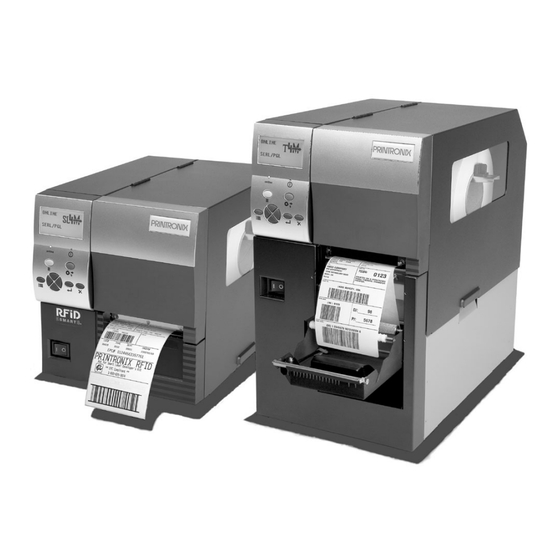
- Page 1 User’s Manual SL4M/T4M Thermal Printers...
-
Page 3: Trademark Acknowledgements
COPYRIGHT © 2006 PRINTRONIX, INC. All rights reserved. Trademark Acknowledgements SL4M and T4M are trademarks of Printronix, Inc. Printronix, IGP, IGP/Auto Label Mapping, PGL, and PrintNet are registered trademarks of Printronix, Inc. HP is a registered trademark of Hewlett-Packard Company. -
Page 5: Table Of Contents
Table of Contents 1 Introduction ............11 The SL4M™/T4M™ Thermal Printer ........... 11 Standard Features ................ 11 Optional Features................13 Thermal Printer Technology ..............14 The Printing Process ..............14 Manual Conventions ................14 Warnings And Special Information ............15 Thermal Consumables................. - Page 6 Table of Contents 3 Standard Interfaces..........53 Overview....................53 Auto Switching ..................53 Centronics Parallel Interface..............54 Centronics Parallel Interface Signals ..........55 IEEE 1284 Parallel Interface..............56 Compatibility Mode................ 56 Nibble Mode .................. 56 Byte Mode ..................56 Signals ..................57 RS-232 Serial Interface ...............
- Page 7 Loading Printer Firmware Through The Network Interface Card..............148 Loading Printer Firmware Via The ftp Utility and Printronix Network Interface Card............150 Loading Printer Firmware Through USB..........152 Downloading Optional Fonts to Flash Memory........153 Download Optional Fonts Via The Parallel or Serial Port.... 154 Download Optional Fonts Via The Ethernet Using ftp....
- Page 8 Load Media ................. 218 Remove Label Liner from the Rewinder........222 Interface Options ................222 Network Interface Card (NIC)............222 Supplies And Accessories ..............223 Genuine Printronix Thermal Transfer Ribbons......223 Genuine Printronix Media............224 Accessories ................. 226 C ASCII Control Codes......... 227...
- Page 9 D General Information .......... 229 Printronix Customer Support Center..........229 Printronix Supplies Department........... 229 Corporate Offices ................ 230 Training Available On Printronix Products ......... 230 Warranty Information ................. 231 Communication Notices..............232 Software License Agreement............. 234 Limited Software Product Warranty ........... 237...
- Page 10 Table of Contents...
-
Page 11: Introduction
Introduction The SL4M™/T4M™ Thermal Printer NOTE: As used in this manual, the terms “SL4M/T4M” and “printer” refer to all models within the series. “SL” refers to all SmartLine RFID models. The SL4M/T4M series consists of a family of high quality, direct thermal and thermal transfer printers specifically designed for printing labels and tags from ®... - Page 12 • STGL Interpreter: SATO • DGL Interpreter: Datamax Interpreters are powerful integration tools that allows the SL4M/T4M printer to function in virtually all legacy ZPL , TEC, IPL, SGL, and DGL application environments without requiring modification to host data stream.
-
Page 13: Optional Features
Optional Features Optional Features Ask your authorized representative about the following enhancement options: • Fonts: A selection of fonts is available to extend the capabilities of the standard resident fonts. • Peel-Liner Rewinder: In label peel-off mode, peels off labels one at a time before printing the next label and rewinds the liner into a discardable roll. -
Page 14: Thermal Printer Technology
Chapter Thermal Printer Technology Thermal Printer Technology Quiet and fast, with excellent print quality, your multifunction thermal printer uses an inline thermal printhead. The thermal printer operates differently from a line matrix or laser printer, because the thermal printer uses a printhead with heating elements and special paper or ribbon. -
Page 15: Warnings And Special Information
Most of these media options can be die-cut for easy label applications. The wide selection of media sizes and face stocks have been tested with Printronix ribbons for print quality and usage. Consult your Genuine Printronix Supplies Catalog, call the Printronix Customer Solutions Center at (714) 368-2686, or access the Printronix web page at www.printronix.com. - Page 16 Chapter Thermal Consumables...
-
Page 17: Operation
Operation Unpacking The Printer The printer is shipped in a carton and protective bag. The top lid of the carton has instructions for removing the internal packing material. Keep all packing material in case repacking is required. CAUTION Avoid touching the electrical connectors to prevent electrostatic discharge damage while setting up the printer. -
Page 18: Installation
Chapter Installation 1. Place the shipping container upright on a flat, level surface. 2. Open the box and remove the first layer of packing material along with any lose items. 3. Remove the accessories box and set it aside. 4. Pull the printer out of the shipping container by using the two plastic straps as handles. - Page 19 Installation c. USB Attach a USB cable with noise suppresion filters on BOTH ends from the computer to the USB connector at the back of the printer. NOTE: The printer supports simultaneous connection of the parallel, serial, and USB interfaces using the Auto Switching feature. Auto Switching is described on page 53.
- Page 20 Chapter Installation Wireless Interface Panel Wireless Antenna Wireless Interface...
-
Page 21: Power Cord Requirements
IMPORTANT For best results, use only genuine Printronix supplies. See “Supplies And Accessories” on page 223. CAUTION DO NOT TOUCH the printhead or the electronic components under the pivoting deck. -
Page 22: Loading Ribbon
Chapter Setting Up The Printer Loading Ribbon For direct thermal media (no ribbon required), go to page 25. Media Cover Flange Ribbon Take-Up Core Ribbon Take-Up Spindle Ribbon Roll Ribbon Supply Spindle Deck Lock Lever Pivoting Deck IMPORTANT Clean the printhead, platen roller, and media sensors every time you change the ribbon. - Page 23 Loading Ribbon Ribbon Take-Up Spindle Ribbon Take-Up Core Ribbon Supply Spindle Alternate Ribbon Path Printhead Ribbon Platen (not shown) Ribbon Guide Roller (2) 5. Thread the end of the ribbon under the ribbon guide rollers, between the platen (rubber drive roller) and the printhead, and between the ribbon take-up and supply spindles.
- Page 24 Chapter Setting Up The Printer Ribbon Take-up Core Ribbon Take-up Spindle Ribbon Leader Deck Lock Lever Printhead Pivoting Deck IMPORTANT Never attach the ribbon to the ribbon take-up spindle without a ribbon take-up core installed. 6. Attach the ribbon to the ribbon take-up core on the ribbon take-up spindle with tape.
-
Page 25: Loading Roll Media
Loading Roll Media Loading Roll Media Media Cover Media Hanger Media Hanger Guide Pivoting Deck Deck Lock Lever IMPORTANT If you are using direct thermal mode, clean the printhead, platen roller, and upper and lower media sensors every time you change the media. See “Cleaning The Printhead, Platen Roller And Media Sensors”... - Page 26 Chapter Setting Up The Printer Side Wall Media Roll Media Hanger Guide Media Hanger 4. Place the media roll onto the media hanger and slide the media roll until it is flush with the printer’s side wall. NOTE: For information regarding smart labels, refer to the RFID Labeling Reference Manual .
- Page 27 Loading Roll Media Printhead Platen (not shown) Media Blue Locking Media Sensor Alternate Width Guide Knob Media Assembly Media Path Media Damper 6. Thread the media under the media damper, through the media sensor assembly, and then between the platen (rubber drive roller) and the printhead.
- Page 28 Chapter Setting Up The Printer Inside Media Media Edge Guide (left edge) Media Sensor Assembly 9. Check the horizontal position of the media sensor assembly (see “Positioning The Media Sensors” on page 44). 10. Align the left (inside) edge of the media with the inside media edge guide.
- Page 29 Loading Roll Media Pivoting Deck Deck Lock Lever 11. Rotate the deck lock lever fully clockwise to close the pivoting deck. This locks the pivoting deck into print position. IMPORTANT Ensure the printhead is down and locked before attempting to advance media or print.
-
Page 30: Loading Fanfold Media
Chapter Setting Up The Printer b. Press the (Feed) key once to verify that the media advances. c. Press the (Pause) key to place the printer online. Loading Fanfold Media Media Cover Fanfold Media Media Hanger Guide Media Hanger Bottom Panel Opening Deck Lock Lever... - Page 31 Loading Fanfold Media Media Sensor Handle Locking Knob Media Damper Media Width Guide Media Sensor Assembly Platen 7. Thread the media under the media damper, through the media sensor assembly, and then between the platen (rubber drive roller) and the printhead.
- Page 32 Chapter Setting Up The Printer Inside Media Edge Guide Media (left edge) 11. Align the left (inside) edge of the media with the inside media edge guide.
- Page 33 Loading Fanfold Media Pivoting Deck Deck Lock Printhead Lever 12. Close the pivoting deck by rotating the deck lock lever fully clockwise. IMPORTANT Ensure the pivoting deck is down and locked before attempting to advance media or print. Failure to do so will cause the “PRINT HEAD UP Close Print Head”...
-
Page 34: Operating Modes
Chapter Operating Modes For direct thermal operation (no ribbon required) or thermal transfer operation (ribbon required): • If you have not run an Auto Calibrate, do so now. See “Running Auto Calibrate” on page 47. • If you have already run an Auto Calibrate, complete the following steps: a. -
Page 35: Controls And Indicators
Power Switch Controls And Indicators Power Switch The power switch is located on the bottom front panel of the printer. To apply power, place the switch in the | (On) position. When you first power on the printer, a series of initialization messages will appear on the LCD (Liquid Crystal Display) on the control panel. -
Page 36: Control Panel
Chapter Controls And Indicators Control Panel The control panel is located on the front of the printer and includes an LCD, indicators, and control keys (buttons). LCD (Liquid Crystal Display) Online Indicator Fault Indicator Pause Key Feed Key Up Key Enter Key Menu Key Cancel Key... -
Page 37: Enter Key
Control Panel Feed Key The Feed Key advances the media one label length in Online and Offline Mode. If there is data in the printer, the printer will print the data before ejecting the label. This key is inactive in all other modes. Menu Key In Online, Offline, or Fault modes, the Menu key causes the printer to enter the Menu mode and the top level menu icons to display. - Page 38 Chapter Controls And Indicators Up Key In Menu mode (at the icon menu level), this key will move to the next row of icons. If on the bottom row it will move up the top row of icons. If at the top of the menu tree, pressing the Up key will go to the bottom of the menu tree.
- Page 39 Control Panel Left Key In Offline mode, this key adjusts the display brightness of the LCD. In Menu mode (at the icon menu level), this key will advance from one menu icon to the previous menu icon. If at the beginning of one row of icons it will move to the end of the other row of icons.
-
Page 40: Media Handling Modes
Chapter Media Handling Modes Media Handling Modes Before you load media, you must decide which media handling mode to use: • Tear-Off Strip (factory default). Printer prints on the media and sends it out the front until the print buffer is empty, then positions the last label over the tear bar for removal. -
Page 41: Printhead Pressure Adjustment
Media Thickness Adjustment Printhead Pressure Adjustment Media Thickness Adjustment Indicator Window Printhead Pressure Switch (not shown, switch is behind the metal tab) Metal Tab Printhead Balance Adjustment Dial This procedure adjusts the printhead pressure to accomodate media of different thicknesses. This will minimize printhead wear and optimize print quality. -
Page 42: Media Width Adjustment
Chapter Printhead Pressure Adjustment Media Width Adjustment Indicator Window Printhead Balance Adjustment Dial Media width adjustment allows you to vary printhead pressure along the platen from one end to the other. If the printhead pressure is out of balance, the printed image will be darker on one side of the label than the other and the media will travel in the direction with the least resistance. -
Page 43: Printhead Alignment
Printhead Alignment Printhead Alignment Align the printhead under the following conditions: to improve the print quality when running difficult media with major differences in thickness, when adjusting for media thickness (with the printhead pressure switch) did not yield adequate print quality, or when you replace the printhead. The printhead must be parallel with the platen for consistent image printing across the label. -
Page 44: Positioning The Media Sensors
Chapter Positioning The Media Sensors 3. Remove the printhead alignment tool (yellow screwdriver) from the tool clip. 4. Use the printhead alignment tool to turn the printhead alignment dial. Turn the printhead alignment dial UP for THICKER stocks and DOWN for THINNER stocks. - Page 45 Positioning The Media Sensors Printhead Alignment Mark Sensor Indicator Gap Sensor Indicator (both sides) Media Sensor (both sides) Assembly Media Sensor Handle Media Sensing Media with Horizontal Black Marks or Inbound Notches 1. Use the media sensor handle to horizontally position the media sensor assembly so that the sensor indicators (embossed on both sides) are aligned with the reference marks on the media.
-
Page 46: Sensing Different Media Types
Chapter Positioning The Media Sensors Sensing Media with Gapped Liner 1. Use the media sensor handle to horizontally position the media sensor assembly so that the sensor indicators (embossed on both sides) are aligned with the reference marks on the media. 2. -
Page 47: Running Auto Calibrate
Running Auto Calibrate Sensing Different Media Types Running Auto Calibrate You can initiate Run Auto-Cal (Auto Calibrate) via the the SENSOR SETUP menu. NOTE: Verify that the Gap/Mark Sensor option (Gap, Mark, or Disable) matches the installed media. See “Sensing Different Media Types” on page 46. -
Page 48: Running Media Profile
Chapter Running Media Profile NOTE: The amount of media sampled during Auto Calibrate is based on the length of a label and transitions detected, without error, between a label and its label length indicators. 8. Press the (Pause) key until OFFLINE displays. 9. - Page 49 Running Media Profile Sensing Different Media Types ↵ 4. Press to enter the SENSOR SETUP menu. ↵ 5. Press the Down key until Run Profile displays and then press ↵ (The printer will continue to print the profile until you press The printer will advance media and continue to print a dynamic profile image depicting the relationship of the label and any label length indicators detected.
-
Page 50: Running Manual Calibrate
Chapter Running Manual Calibrate Running Manual Calibrate Manual Calibrate should be performed only when the values derived from Auto Calibrate fail to improve the media sensors’ ability to sense label length indicators on the installed media. You must first enable Admin User in the PRINTER SETUP menu before accessing or initializing Run Manual Cal (manual calibrate) in the SENSOR SETUP menu. - Page 51 Running Manual Calibrate Sensing Different Media Types 12. During the last step of Run Manual Cal, the printer advances the media and attempts to detect the label length indicators and stop at the Top-of-Form position. The Sensed Distance value will then display for one second.
- Page 52 Chapter Running Manual Calibrate...
-
Page 53: Standard Interfaces
Standard Interfaces Overview This chapter describes the host interfaces provided with the printer. The printer interface is the point where the data line from the host computer plugs into the printer. The interface processes all communications signals and data to and from the host computer. Plus, with the Auto Switching feature, you can configure the printer to accept several interfaces at the same time. -
Page 54: Centronics Parallel Interface
Chapter Centronics Parallel Interface Centronics Parallel Interface Table 4. Centronics Interface Connector Pin Assignments Input Signals Output Signals Miscellaneous Signal Signal Signal DATA LINE 1 ACKNOWLEDGE CHASSIS GROUND Return Return DATA LINE 2 ONLINE GROUND Return Return DATA LINE 3 FAULT Spares Return... -
Page 55: Centronics Parallel Interface Signals
Centronics Parallel Interface Signals Centronics Parallel Interface Signals Table 5. Centronix Parallel Interface Signals Signals Purpose Data Lines 1 through 8 Provide eight standard or inverted levels from the host that specify character data, plot data, or a control code. Data Line 8 allows access to the extended ASCII character set. -
Page 56: Ieee 1284 Parallel Interface
Chapter IEEE 1284 Parallel Interface IEEE 1284 Parallel Interface The IEEE 1284 supports three operating modes, which are determined by negotiation between the printer and the host. Compatibility Mode This mode provides compatibility with Centronics-like host I/O (see Table 4). Data is transferred from the host to the printer in 8-bit bytes over the data lines. -
Page 57: Signals
Signals Signals Table 6 lists each of the signals associated with the corresponding pins on the IEEE 1284 interface. Descriptions of the signals follow. Table 6. IEEE 1284 Signals Type of Mode Source of Data Compatible Nibble Byte Host nStrobe HostClk Host/Clk Host/Printer... - Page 58 Chapter IEEE 1284 Parallel Interface Table 6. IEEE 1284 Signals (continued) Type of Mode Source of Data Compatible Nibble Byte Signal Ground (Data 7) Signal Ground (Data 8) Signal Ground (PError, Select, nAck) Signal Ground (Busy, nFault) Signal Ground (nAutoFd, nSelectIn, nInit) Host nInit Printer...
-
Page 59: Rs-232 Serial Interface
RS-232 Serial Interface Signals nReverse Request. Driven by the host. Resets the interface and forces a return to Compatibility Mode idle phase. nData Available / nPeripheral Request. Driven by the printer. Indicates the printer has encountered an error. (Data bits 1 and 5 in Nibble Mode.) 1284 Active / nAStrobe. - Page 60 Chapter RS-232 Serial Interface Data Carrier Detect (DCD). Status signal to the printer. The ON condition is required for the printer to receive data. Data Terminal Ready (DTR). Control signal from the printer. Subject to configuration.
-
Page 61: Configuring The Printer
Configuring The Printer Overview This chapter provides information about: • Setting, saving, modifying, and printing configurations • Configuration menus Setting Printer Configuration Parameters Configuration parameters are set from the control panel or are retrieved from the printer’s memory. The parameters define how the printer will respond to command and interface signals from the host computer. - Page 62 Chapter Overview NOTE: In menus with numeric ranges of more than 50 numbers, hold down the right or left key for more than 2 seconds to move through the range in increments of 5. To move in increments of 1 again, release your hold on the right or left key.
-
Page 63: Selecting A Menu Option
Selecting A Menu Option Selecting A Menu Option ↵ To select an option, you need to press the key. By default, however, the ↵ key is “locked” when the printer is turned on to prevent accidental changes to the configuration menu. If you press the ↵ key when the key is locked, the ↵... -
Page 64: Changing Printer Settings
Chapter Hidden Menus Changing Printer Settings You can change (or “configure”) printer settings, such as print speed or emulations, through the control panel as follows: 1. Press the key to enter the Menu configuration. MEDIA SETUP is selected. ↵ 2. Press the key to enter the MEDIA SETUP menu. -
Page 65: Menu Overview
Menu Overview Changing Printer Settings Menu Overview SENSOR PRINTER MEDIA EMULATION SETUP SETUP SETUP Set the menus needed Control various Select the correct Select the desired to configure the parameters related to media sensing for the Active IGP emulation, printer. print quality, media, and media type installed other emulations, and... -
Page 66: Main Menu
Chapter Main Menu Main Menu MEDIA SENSOR PRINTER EMULATION SETUP SETUP SETUP (page 68) (page 79) (page 101) (page 86) Print Intensity Gap/Mark Sensor Select SMT: Status Print Speed Run Auto-Cal Emulation Setup PAA: Status Print Mode Run Profile Power Saver Time Media Handling Sensed Distance Pwr Save Control... - Page 67 Main Menu Changing Printer Settings INTERFACE RFID CONFIGURATION DIAGNOSTICS (page 110) (page 133) (page 130) Host Interface Save Config. Printer Tests Refer to the RFID Ethernet Port Load Config. Test Count Labeling Reference Ethernet Setting Print Config. Software Build Manual. WLAN Setting Delete Config.
-
Page 68: Media Setup Menu
Chapter MEDIA SETUP Menu MEDIA SETUP Menu MEDIA SETUP (from page 66) Print Intensity Print Speed Print Mode Media Tear Off Handling Continuous Adjust 4 ips* Standard* Transfer* Tear-Off Strip* 0.00* -15 to 15 1 ips to 10 ips Direct Peel-Off Tear-Off -0.50 to 0.20... -
Page 69: Media Setup Submenus
MEDIA SETUP Submenus MEDIA SETUP Submenus Print Intensity This option specifies the level of thermal energy from the printhead to be used for the type of media and ribbon installed. Large numbers imply more heat (thermal energy) to be applied for each dot. This has a significant effect on print quality. - Page 70 Chapter MEDIA SETUP Menu • Cut. When the optional media cutter is installed, it automatically cuts media after each label is printed or after a specified number of labels have been printed when a software cut command has been issued. It cuts continuous roll paper, labels, or tag stock.
- Page 71 MEDIA SETUP Submenus Label Length This option specifies the user-selected Label Length in inches or millimeters. In most applications, the user-selected Label Length will match the physical label length. Physical label length is the actual label length of the media installed.
- Page 72 Chapter MEDIA SETUP Menu The allowable Label Length range is 00.1 to 99.0 inches (2.5 - 2514.6mm). The factory default is 6 inches. Maximum Label Length range is dependent on the Label Width value selected, printhead installed (203 or 305 DPI). NOTE: See “Set Label Length”...
- Page 73 MEDIA SETUP Submenus Orientation This menu item selects the image orientation to be used when printing the label. • Portrait. Portrait refers to vertical page orientation, where the height of a page is greater than its width. The top edge of the image is parallel to the leading edge of the media.
- Page 74 Chapter MEDIA SETUP Menu Trailing Edge 4 inches The top edge of FEED the image is parallel to the trailing edge of the 6 inches media. Leading Edge • Inv. Landscape. Inverse Landscape refers to horizontal orientation, where the width of a page is greater than its height. The top edge of the image is the right edge of the media (the left edge of the image is the trailing edge of the media).
-
Page 75: Print Direction
MEDIA SETUP Submenus Print Direction This option determines the basic print image orientation. NOTE: Print Direction will not change the orientation of any print test patterns in the DIAGNOSTIC menu. Print Direction has two options: • Head First • Foot First For example, with Portrait orientation, when you select Head First, the top-of- form will come out of the printer first. - Page 76 Chapter MEDIA SETUP Menu Tear-Strip Time When Media Handling is set to Tear-Off Strip or when Media Handling is set to Continuous and Continuous Mode is set to Tear Strip Full, Tear-Strip Time specifies the number of seconds after the buffer is empty that the printer will wait before it advances media to the tear bar position.
- Page 77 MEDIA SETUP Submenus • An occasional blank label appears within a print job (in between printed labels). When Clip Page is set to Disable, the printer ignores any pre-printed dark marks or multiple gaps on a label that could mistakenly be detected as the next top-of-form position based on the specified Label Length value.
- Page 78 Chapter MEDIA SETUP Menu Units This item selects either millimeters or inches as the unit of measure. The options are In Inches (factory default) and In Millimeters. Set Label Length This feature selects whether the Sensed Distance value derived from an Auto or Manual Calibrate will be used to set the Label Length value in the MEDIA SETUP menu.
-
Page 79: Sensor Setup Menu
SENSOR SETUP Menu MEDIA SETUP Submenus TOF Adjust This opton sets the distance from the Top Of Form (TOF) that is left blank (unprinted) after a label has been removed in Tear-Off Strip. Normally printing is done starting at TOF, but when this mode is enabled the start position for printing can be adjusted from 0.00 to 0.40 inches from TOF (in increments of 0.01 inch). -
Page 80: Sensor Setup Submenus
Chapter SENSOR SETUP Menu SENSOR SETUP Submenus Gap/Mark Sensor The available options specify the sensor type needed for detecting the Top-of-Form position on media with label length indicators (gaps, notches, holes, or black marks). • Gap (factory default). Select when using media with a liner space between die-cut labels or when using tag stock with holes as label length indicators on white background media. -
Page 81: Sensed Distance
SENSOR SETUP Submenus Run Profile This feature provides a graphical printout showing the relationship of the Paper Out Threshold and the Gap/Mark Threshold. The profile printout assists you in setting the thresholds for difficult media. This includes preprinted labels, and labels with poor gap/media dynamic range. When selected, the printer will advance media and print the media profile along the length of each label. - Page 82 Chapter SENSOR SETUP Menu Run Manual Cal Run Manual Cal is another method of improving the printer’s media sensing and is only used when Auto Calibrate has failed or the Gap/Mark Threshold or Paper Out Threshold values derived from Auto Calibrate do not improve the media sensors’...
-
Page 83: Gap Length
SENSOR SETUP Submenus Online Auto-Cal NOTE: Online Auto-Cal will not function when there is data in the the buffer and when Error Recover (in MEDIA SETUP menu) is enabled (see page 68). The options for Online Auto-Cal are: • Disable (factory default). •... - Page 84 Chapter SENSOR SETUP Menu Cal in Peel Mode This option allows you to perform a calibration (Run Auto-Cal or Pwr Up Auto-Cal) in Peel-Off Media Handling mode. • Disable (factory default). The printer will not permit calibration and a “CANNOT CALIBRATE/Disable Peel-Off” message will briefly display. Additionally, if “Pwr Up Auto-Cal”...
- Page 85 SENSOR SETUP Submenus Use Label Length Determines whether or not the Label Length value set in the MEDIA SETUP menu is used during Run Auto-Cal. • Disable (factory default). Run Auto-Cal relies exclusively in its ability to detect varying transitions between labels and gaps, notches, holes, or black marks while advancing media during the calibrate process to determine Sensed Distance.
-
Page 86: Emulation Menu
BEFORE you reconfigure an emulation, print a configuration sheet to see all current settings. The PGL emulation is the software based Printronix Graphics Language (PGL) for the Printronix thermal printer family. It is based upon, and compatible with, the IGP-100/200/400 board. It includes the following features: On-Line Form and Label Generation makes it easy to create forms or labels with a “preprinted”... - Page 87 EMULATION Menu Overview Alphanumeric data can appear as prepositioned “fixed” information (entered when the form is created), be overlayed onto the form (positioned in a specific location after the form is created), or may be dynamically merged with the form. Selectable Bar Codes provide you with the appropriate bar code for your application using standard wide-to-narrow ratios.
- Page 88 Chapter EMULATION MENU EMULATION (from page 66) Select Emulation Setup PGL* STGL Setup Setup Setup Setup See page 89 or Refer to the ZGL Refer to the TGL Refer to the IGL refer to the PGL Programmer’s Programmer’s Programmer’s Programmer’s Reference Manual Reference Manual Reference Manual...
-
Page 89: Pgl Setup
PGL Setup Overview PGL Setup SETUP (from page 86) Character Standard Select LPI Define CR Define LF Group Sets Code Code See page 91 0) ASCII* 9) Spanish CR = CR* LF = LF* 1) German 10) Italian 1 to 1000 CR = CR + LF LF = CR + LF 2) Swedish... - Page 90 Chapter EMULATION MENU PGL SETUP (continued from page 89) I-2/5 User-Def Lead Trunc Vertical Selection Compatbl. Ratio PDF Dist Dyn Data Adjust Leading Zero* Disable* Enable* 0.10 Inches* Disable* 0 Dots* Trailing Space Enable Disable 0.01 inches to Enable -20 to 20 dots X2 DPD 0.10 inches Modulo 7 CD...
- Page 91 PGL Setup Overview Character Group (from page 89) Standard Arabic Sets Cyrillic Sets European Greek Sets Sets* Sets 0) ASCII* ASMO 449* Code Page 866* Latin 2 8859-2* DEC 256 Greek* 1) German ASMO 449+ Cyrillic CP 437 Code Page 852 ELOT 928 Greek 2) Swedish ASMO 708...
-
Page 92: Emulation Submenus
Chapter EMULATION MENU EMULATION Submenus Select This function allows you to activate any resident emulation listed in the menu. The factory default is PGL. There are two methods for selecting the desired emulation: • Select the emulation under the Select menu option and save it as Power-up Config. - Page 93 EMULATION Submenus Define CR Code This option controls the action of the printer when it receives a Carriage Return code (0D hex) from the host computer. If this feature is enabled, each time the printer receives a carriage return, it inserts an additional Line Feed code (0A hex) into the data stream.
- Page 94 Chapter EMULATION MENU Slash 0 This parameter allows you to print the numeral “0” with or without the slash. This option applies to all character sets except OCR A and OCR B. • Disable (factory default). Zero is printed without a slash. •...
- Page 95 EMULATION Submenus Var Form Type • Add Nothing (factory default). When selected, no action is taken. • Add ;0. When selected, the form length ends at the longest printed ∼ element. (Same as CREATE;filename;0) • Add ;X. When selected, the form length is the same as the physical page length (the Label Length menu under MEDIA SETUP).
- Page 96 Chapter EMULATION MENU Power on IGP/PGL You can set the IGP/PGL feature so that it is enabled or disabled when the printer is powered on. • Enable (factory default). IPG/PGL is enabled when the printer is powered on. (The PGL feature is initialized in Normal mode). •...
- Page 97 EMULATION Submenus Select Char This parameter selects which character to discard when Ignore Mode is enabled. • 0 (the default) • 0 - 255. Any character from 0 to 255 in decimal. Do FF at TOF Determines whether the printer, with media already set at the TOF (Top-of- Form) position, will advance media to the next TOF position upon receipt of an FF command.
- Page 98 Chapter EMULATION MENU PGL Normal This option determines whether PGL passes the text data in Normal mode or whether PGL will print the data text itself. • LP+ Menu (factory default). PGL will pass the text data to the menu only in default setting state.
- Page 99 EMULATION Submenus User-Def Ratio This option allows you to ignore the user-defined barcode ratio and replace it with the default ratio (X1). • Enable (factory default). Allows the user-defined barcode ratio. • Disable. The user-defined barcode ratio will be replaced with the default ratio (X1).
- Page 100 Chapter EMULATION MENU Boundary Check This option turns on or off the page boundary check for all print elements. • Enable (factory default). When enabled, an out of bound error is reported if the print element is out of the page boundary. •...
-
Page 101: Printer Setup Menu
PRINTER SETUP Menu EMULATION Submenus PRINTER SETUP Menu PRINTER SETUP (from page 66) SMT: Status Power Saver Pwr Save Display Alarm PAA: Status Time Control Language Disable* Disable* 15 minutes* Enable* English* Enable 30 minutes Disable German Cont. Beep Enable 45 minutes French 60 minutes... -
Page 102: Printer Setup Submenus
Chapter PRINTER SETUP Menu PRINTER SETUP (continued from page 101) Print Auto Locking Set Lock Key Max Font Max Cache File List Buffer Memory Disable* 100 KBytes* 900 KBytes* Enable 100 to 1800 Kbytes 50 to 2000 KBytes Max Cached Standard Bold Extra Bold... - Page 103 PRINTER SETUP Submenus PAA: Status See “Printronix Application Adapter” in the Remote Management Software Advanced Tool Kit User’s Manual . • Disable (factory default). The printer disables the use of PAA functionality. • Enable. The printer enables the use of PAA functionality.
-
Page 104: Cancel Key
Chapter PRINTER SETUP Menu Ptx Setup Parse • Enable (factory default). Will parse and execute the PTX SETUP commands. • Ignore. Will parse the PTX SETUP commands but not act on them. • Disable. Will not parse the PTX SETUP commands so they will print out as text. - Page 105 PRINTER SETUP Submenus Del Set frm Fls This option deletes downloaded overlay set(s) from flash memory. Ld Set from Fls This option loads downloaded overlay set(s) from flash memory. Save Set to Fls This option saves downloaded overlay set(s) to flash memory. Del Set from RAM This option deletes the downloaded overlay set(s) from RAM.
- Page 106 Chapter PRINTER SETUP Menu Print File List Prints a summary of the files stored in flash memory and several statistics on File System usage. Auto Locking Disable (factory default). The ↵ (ENTER) key must be locked manually. • Enable. The printer automatically locks the ↵ key five minutes after the •...
- Page 107 PRINTER SETUP Submenus Max Cache Memory The Maximum Cache Memory option specifies the size of the memory block that can be allocated to the font cache. The font cache stores bitmaps that are created on demand from the font outlines stored on the printer flash. The cache allows the printer to print scalable fonts at optimum speed.
- Page 108 Chapter PRINTER SETUP Menu Standard Chars. This menu entry permits you to adjust the thickness or font weight of standard text fonts. The range is 0 to 512, and the factory default is 340. Bold Chars. This menu entry permits you to adjust the thickness or font weight of bold text fonts.
- Page 109 PRINTER SETUP Submenus Batch Counter Displays the number of pages remaining in a print job. • Disable (factory default). The # Pages remaining to be printed will not display. Instead, the Active emulation and interface will display on the second line of the control panel LCD. •...
-
Page 110: Interface Menu
Chapter INTERFACE Menu INTERFACE Menu INTERFACE (from page 67) Host Ethernet Ethernet WLAN Interface Port Setting Setting Auto Switching* Timeout* IP Address Preamble IP Address Centronics 10 sec* Subnet Mask Default* Subnet Mask Serial 1-60 sec Gateway Address Short Gateway Address IEEE 1284 Switch Out On MAC Address... - Page 111 INTERFACE Menu PRINTER SETUP Submenus Parallel Port (from page 110) Port Data Bit 8 PI Ignored Buffer Size Auto Trickle Trickle Time Type in K IEEE 1284* Enable* Enable* Disable* 1/4 sec* Disable Disable Disable 1-16 Enable 1/2 sec Centronics 1 sec 2 sec 4 sec...
- Page 112 Chapter INTERFACE Menu Serial Port (from page 110) Baud Word Stop Bits Parity Data Buffer Size Rate Length Protocol in K 9600 BAUD* None* XON/XOFF* 600 BAUD to ETX/ACK 1 - 16 115200 BAUD Even ACK/NAK Mark Series1 1Char Sense Series1 2 Char Trickle Timeout...
-
Page 113: Interface Submenus
INTERFACE Submenus Printer Mgmt (from page 110) PNE Port Mgmt Select Port Baud Rate Word Stop Bits Protocol Length Disable* PXML* Debug* 9600 BAUD* Serial Host 2400 BAUD TO Ethernet 115200 BAUD Parity Modem Modem NUM Modem Dial PNE Port Status Method Number... -
Page 114: Parallel Port
Chapter INTERFACE Menu Parallel Port • Port Type. This menu item selects the type of printer parallel port interface to be used with the host. The options are IEEE 1284 (factory default), Disable, and Centronics. • Data Bit 8 • Enable (factory default). - Page 115 INTERFACE Submenus • Trickle Time. When the printer is printing data from a host and a second print job is received by the printer from a different host, Trickle Time prevents the second host from timing out while it is waiting for its data to be printed.
-
Page 116: Usb Port
Chapter INTERFACE Menu • Busy on Strobe • Enable (factory default). Asserts a busy signal after each character is received. • Disable. Asserts a busy signal only when the print buffers are full. • Latch Data On. Specifies whether the data is read on the leading or trailing edge of the data strobe signal. - Page 117 INTERFACE Submenus • Baud Rate. Sets the baud rate of the serial interface used to communicate to the PNE. Baud rate is the speed at which serial data is transferred between the PNE and the printer. The options for the RS-232 interface are 600, 1200, 2400, 4800, 9600, 19200, 38400, 57600, and 115200 Baud.
- Page 118 Chapter INTERFACE Menu • Dial Method • Tone (factory default). Sets the modem to use the tone dialing method. • Pulse. Sets the modem to use the pulse dialing method. • PNE Port Number. This menu selects the port number the printer expects the PNE to connect through.
- Page 119 INTERFACE Submenus • Data Protocol. You can select one of the following serial interface protocols to meet the host interface requirements. • XON / XOFF (factory default). The printer controls the flow of communication from the host by turning the transmission on and off. In some situations, such as when the buffer is full or the timing of signals is too slow or too fast, the printer will tell the host to stop transmission by sending an XOFF character.
- Page 120 Chapter INTERFACE Menu The response characters are described below. Printer State Response Online and Buffer Empty Online and Buffer Full Offline and Buffer Empty Offline and Buffer Full • Series1 2 Char. This protocol behaves exactly the same as the Series 1 Char except there is a two-character response to the host.
- Page 121 INTERFACE Submenus • Timeout. This is the value used by the printer to time out from the current port and check the other selected Port Types for data to print. When the printer has not received data from the host after a certain period of time, it needs to time out in order to service the other ports.
- Page 122 Chapter INTERFACE Menu • Idle Response. This option is for the Series1 protocol. • Disable (factory default). • Enable. The printer sends a response character every two seconds while the number of valid bytes in the buffer is less than 75 percent of the buffer size.
- Page 123 INTERFACE Submenus Table 11. ENQ/STX Status Byte Printer Status Set when the printer is not online or the buffer is full. Set when the printer is offline. Clear during a paper out or RibbonMinder fault. Always set. Set during a Head Open fault. Set during a buffer overflow fault.
-
Page 124: Ethernet Port
Chapter INTERFACE Menu Ethernet Port • Timeout. This is the value used by the printer to time out the current port and check the other selected Port Types for data to print. When the printer has not received data from the host after a certain period of time, it needs to time out to service the other ports. - Page 125 INTERFACE Submenus • Gateway Address. This item allows you to set the Gateway Address for the TCP/IP protocol in four three-digit segments (SEG1 through SEG4). If the Gateway Address is assigned by Bootp, ARP or DHCP, it is dynamic and read-only. The defaults for the SEG1 through SEG4 are 000, 000, 000, and 000.
- Page 126 Chapter INTERFACE Menu • Ethernet Speed. This menu appears only if a 10/100Base-T Network Interface Card (NIC) is installed. The Ethernet Speed menu has five different speed modes to allow compatibility with different systems and networks: • Auto Select (factory default). Tells the 10/100Base-T NIC to perform an auto detection scheme and configure itself to be 10 Half Duplex, 10 Full Duplex, 100 Half Duplex, or 100 Full Duplex.
- Page 127 INTERFACE Submenus WLAN Setting • IP Address. This item allows you to set the IP Address for the TCP/IP protocol in four three-digit segments (SEG1 through SEG4). If the IP Address is assigned by Bootp, ARP or DHCP, it is dynamic and read- only.
- Page 128 Chapter INTERFACE Menu • Operation Mode. Allows you to select the way the Wireless option communicates: • Infrastructure (factory default). The Wireless option must go through an Access Point. • Pseudo IBSS. Proprietary, peer-to-peer communication (without an Access Point). The two peers must be specific to one manufacturer. •...
- Page 129 INTERFACE Submenus • Transmit Power. The power level as a percentage of full power. The range is 0 - 100%, and the factory default is 100%. • Internat. Mode. When enabled, the Wireless option adapts to international frequency requirements in Europe. The options are Disable (factory default) and Enable.
-
Page 130: Configuration Menu
Chapter CONFIGURATION MENU CONFIGURATION MENU CONFIGURATION (from page 67) Save Load Print Delete Power-Up Protect Config. Config. Config Config. Config. Configs. Current* Factory* Disable* 1 to 8 1 to 8 Factory 1 to 8 1 to 8 Enable Factory Power-Up 1 to 8 Name Name... -
Page 131: Configuration Submenus
CONFIGURATION Submenus CONFIGURATION Submenus Save Config This option allows you to save up to eight unique configurations to meet different print job requirements. This eliminates the need to change the parameter settings for each new job. The configurations are stored in memory and will not be lost if you turn off the printer. - Page 132 Chapter CONFIGURATION MENU Name Config 1 to Name Config 8 You may specify a 15-character name which can be used to refer to a configuration. The name you enter for a configuration will be used in the Load Config., Save Config., Print Config., Delete Config., and Power-Up Config. menus.
-
Page 133: Diagnostics Menu
DIAGNOSTICS Menu CONFIGURATION Submenus DIAGNOSTICS Menu DIAGNOSTICS (from page 67) Print Test Software Feature Hex Dump Print Tests Count Build File Mode Error Log Checkerboard* 5 Pages* XXXXXX XXXXXX- XXX Disable* Grey 10 Pages Enable Grid Continuous 1 Page Current Config Left Test 2 Pages Right Test... -
Page 134: Diagnostics Submenus
Chapter DIAGNOSTICS Menu DIAGNOSTICS Submenus Print Tests The printer tests below allow you to check for proper printer operation and print quality: • Checkerboard (factory default). This pattern helps identify marginal printhead elements, quality of edge sharpness, and uneven print quality. •... - Page 135 DIAGNOSTICS Submenus Software Build This is the reference number which includes the program file part number and revision number of the software installed in the printer, e.g., 358186 V1.07G. Feature File Displays the part number only when a feature file has been installed. Hex Dump Mode •...
-
Page 136: Saving A Configuration
Chapter Saving A Configuration Head On Time Displays the time that power has been applied to the printhead since the last Reset Head Data operation. This value is set to zero at the factory after burn- in testing. Reset Head Data Resets all printhead statistics values (Head Prt Dist and Head On Time) to zero. -
Page 137: Auto Save Configuration
Auto Save Configuration DIAGNOSTICS Submenus 6. When the desired number displays, press the ↵ key to select it. The following message displays briefly: Saving Configuration When processing is completed, the display shows: Save Config. NOTE: If the configuration number has been previously saved and Protect Config. - Page 138 Chapter Auto Save Configuration has been saved in that configuration number. The first empty configuration found is used as the open configuration. The Auto Save Configuration cannot save a configuration to the Factory Configuration. If the active configuration is the Factory Configuration then the Auto Save Configuration function must find an open configuration into which to save the active configuration.
-
Page 139: Specifying A Power-Up Configuration
Specifying A Power-Up Configuration DIAGNOSTICS Submenus Specifying A Power-Up Configuration You can specify any one of the nine configurations (1-8 or Factory) as the power-up configuration: 1. Press the key to enter the menu configuration. 2. Press the Right key until the following displays: CONFIGURATION ↵... -
Page 140: Modifying A Saved Configuration
Chapter Modifying A Saved Configuration Modifying A Saved Configuration You can change a saved configuration by rewriting over it. For example, you can modify Config. 1, shown below. Suppose you want to keep all the settings but you want to select the parallel Centronics interface instead of the IEEE 1284 interface. -
Page 141: Printing A Configuration
Printing A Configuration DIAGNOSTICS Submenus b. Press the Left or Right keys to cycle through the options (1-8). When the desired number displays, press the ↵ key to select it. The following message displays: Deleting Configuration Then, the following displays when it is deleted: Delete Config. -
Page 142: Loading A Saved Configuration
Chapter Loading A Saved Configuration 6. When the desired option displays, press the ↵ key. The printer prints the specified configuration. NOTE: If the configuration you want to print has not been saved, the following message displays momentarily: CONFIG. DOES NOT EXIST/Save First This message indicates that no configuration menu has been saved under the configuration value you have selected and therefore cannot... -
Page 143: Downloading Firmware
Downloading Firmware Loading Flash Memory Flash memory is contained in a SIMM (single in-line memory module) located on the controller PCBA. Printer control languages and printer operating system software are loaded into flash memory at the factory, but there are occasions when you may have to load this software: •... -
Page 144: Loading Printer Firmware Using The Firmware Download Utility
Chapter Loading Printer Firmware Using The Firmware Download Utility Loading Printer Firmware Using The Firmware Download Utility The Firmware Download Utility (FDU) allows you to load program files into the printer with an easy to use graphical interface. The FDU is a utility program included on the CD that comes with the printer. -
Page 145: Loading Printer Firmware Through The Parallel Or Serial Port Using Dos
12. Identify which emulation set you want to load into the printer and note the filename that corresponds to that emulation. The filename is a six digit number plus .exe or .prg. For example: 123456.exe or 123456.prg This is the file you will download into the printer. 13. - Page 146 Chapter Loading Printer Firmware Through The Parallel Or Serial Port Using DOS 7. Wait until you see “Status: Firmware Download Mode” on the LCD before doing the next step. This can take about a minute to appear, depending on the emulations and interfaces installed in the printer. 8.
-
Page 147: Loading Printer Firmware If Flash Contains Corrupt Code
18. If required, reconnect the data input cable(s) to the printer. 19. Set the printer power switch to | (On). 20. Using the configuration printout(s) you made in step 1 on page 145, restore the printer configurations. (Refer to “Loading A Saved Configuration”... -
Page 148: Loading Printer Firmware Through The Network Interface Card
Chapter Loading Printer Firmware Through The Network Interface Card 14. To load the file through the LPT1 parallel port on the computer, type the following at the command prompt on the computer: filename.exe -pb<Enter> where filename .exe is the file name you noted in step 11. This command decompresses the file on the hard drive and copies it as a binary file into the flash memory on the printer controller board. - Page 149 9. Identify which emulation set you want to load into the printer and note the filename that corresponds to that emulation. The filename is a six digit number plus .prg. For example: 123456.prg This is the file you will download into the NIC. 10.
-
Page 150: Loading Printer Firmware Via The Ftp Utility And Printronix Network Interface Card
Windows (95, 98, Me, NT, 2000, XP) systems. Ftp can be used to send files to the Printronix Network Inteface Card (NIC). The file to be sent to the printer must be present on the host computer, in a known location. - Page 151 8. Set the transfer mode. Select binary mode for flash downloads. Type bin<Enter> 9. Start the file transfer. Type put xxxxx.xxx<Enter>. Use the actual file name in place of xxxxx.xxx. 10. Wait for ftp to indicate the download is complete. Print jobs (not flash downloads) only It is possible to send additional print jobs by repeating steps 9 and 10.
-
Page 152: Loading Printer Firmware Through Usb
Chapter Loading Printer Firmware Through USB Loading Printer Firmware Through USB Normally the Host communicates with the printer’s USB port with a Windows Driver. The Windows Driver cannot be used to transfer binary data to the printer, such as the data contained in a Program Download. To do a Program Download through the USB Port perform the following steps: 1. -
Page 153: Downloading Optional Fonts To Flash Memory
Downloading Optional Fonts to Flash Memory Optional fonts are stored on a 3.5 inch floppy diskette that contains file names comprised of a part number with a .dwn extension. You will insert this diskette in your IBM-compatible computer and use either the parallel, serial, or ethernet port to download the desired font(s) to the printer’s flash memory. -
Page 154: Download Optional Fonts Via The Parallel Or Serial Port
Chapter Downloading Optional Fonts to Flash Memory Download Optional Fonts Via The Parallel or Serial Port 1. Set the printer power switch to O (Off). 2. Connect a parallel data cable to the LPT1 port or a serial cable to the COM1 port of an IBM-compatible computer running the Windows (95, 98, Me, NT, 2000, or XP) operating system. - Page 155 Download Optional Fonts Via The Parallel or Serial Port 13. At the command prompt type: copy /b filename.dwn LPT1<Enter> (where filename .dwn is file name you noted in step 12.) NOTE: If you are loading the file using the LPT2 port on the computer, type the following command: copy /b filename.dwn LPT2<Enter>...
-
Page 156: Download Optional Fonts Via The Ethernet Using Ftp
Labeling Applications Download Optional Fonts Via The Ethernet Using ftp Printronix offers scalable fonts as optional sets of four or more files. The fonts are provided on MS-DOS formatted 3.5 diskettes. The files on the diskettes have a .DWN extension, indicating they have a header allowing them to be downloaded into flash memory. -
Page 157: Downloading Truetype Fonts
PRINTER SETUP Optimize & Reboot. Printronix Windows Driver A TrueType font can be downloaded from a PC through the Printronix Windows Driver. 1. Load the Printronix Windows driver provided with your printer on the Manuals and Utilities CD on Windows 2000/XP. -
Page 158: Create And Send Download File - Online (Pgl Only)
Chapter Downloading TrueType Fonts Create And Send Download File – Online (PGL Only) A TrueType font can be loaded by creating a file that appends a PGL command to the font and then sending that file to the printer. Use the PGL FONTLOAD command: ~FONTLOAD;FontName;FontSize;Location where... -
Page 159: Using Ptx_Setup
Using PTX_SETUP Using PTX_SETUP PTX_SETUP can be used to load TrueType fonts into the file system. Please see the PTX_SETUP chapter in the PGL Programmer’s Reference Manual for details. Example: ! PTX_SETUP FILE_IO-CAPTURE; “ARIAL.TTF”. PTX_END Arial TrueType font binary data NOTE: Do not add any LF/FF at the end of the binary data !PTX_SETUP FILE_IO-CAPTURE;””. - Page 160 Chapter Downloading TrueType Fonts...
-
Page 161: Routine Care And Troubleshooting
Routine Care And Troubleshooting Cleaning Depending on the media used, the printer may accumulate residues (media dust, adhesives, etc.) as a by-product of normal printing. To maintain top printing quality, you should remove these residues by cleaning the printer periodically. Exterior Cleaning Clean the exterior surfaces with a clean, lint-free cloth. -
Page 162: Cleaning The Printhead, Platen Roller And Media Sensors
Chapter Cleaning Cleaning The Printhead, Platen Roller And Media Sensors NOTE: You do not need to turn off the printer before cleaning the printhead, platen roller, or media sensors. Printhead Cleaning As you use your printer, the printhead may become dirty which can result in poor print quality. - Page 163 Cleaning The Printhead, Platen Roller And Media Sensors Printhead Heating Elements (underneath, not shown) Pivoting Deck Deck Lock Lever Printhead Assembly Media Sensor Assembly Printhead Release Lever Platen Roller Print Element Figure 3. Cleaning the Printhead, Platen Roller, and Media Sensors...
- Page 164 Chapter Cleaning 1. Rotate the deck lock lever counterclockwise to open the pivoting deck and remove any media and ribbon (if loaded) to gain access to the printhead heating elements area. 2. Gently rub a cotton swab with Isopropyl alcohol across the printhead heating elements (light brown area).
-
Page 165: Printer Tests
Improving Processing Time Printer Tests A sequence of automatic tests is performed during printer power-up. If any faults are detected at that time, a fault message will display. Before setting the printer for online operation, run a test print. The printer tests option has various tests which allow you to check for proper printer operation and print quality. -
Page 166: Data Exchange
Chapter Troubleshooting Common Situations Data Exchange Many things can cause data loss or communications problems. This section suggests some ways to isolate these problems and determine their cause. Handshaking Handshaking is the exchange of signals between two computers (or a computer and a peripheral input or output device) to indicate the status of the data being transferred. -
Page 167: Controlling Print Quality
Controlling Print Quality Controlling Print Quality Three factors have the greatest effect on print quality: • The amount of heat applied by the printhead (print intensity) • The speed at which media is moving under the printhead (print speed) • The amount of printhead pressure. -
Page 168: Replacing The Printhead
Chapter Replacing The Printhead Replacing The Printhead 1. Set the printer power switch to O (Off). WARNING Always unplug the printer power cord from the printer or power outlet before doing any installation procedure. Failure to remove power could result in injury to you and damage the equipment. When applicable, you will be instructed to apply power. - Page 169 Replacing The Printhead Determining Printhead Wear CAUTION To prevent electrostatic damage to electronic components, ground yourself by touching an unpainted part of the printer frame before handling and installing the printhead. 6. Touch an unpainted part of the printer frame before touching the printhead.
-
Page 170: Restore The Printer To Operation
Chapter Restore The Printer To Operation Restore The Printer To Operation 1. Inspect the light brown area of the printhead for smudges or fingerprints. If necessary, gently clean the light brown area with a soft, lint-free cloth (or a cotton swab) moistened with isopropyl alcohol. 2. -
Page 171: Solving Other Printer Problems
Solving Other Printer Problems Solving Other Printer Problems Table 14. Printer Problems and Solutions Symptom Solution/Explanation Communications Failures. 1. Check the interface cable. 2. Check the configuration to ensure the correct interface is enabled. 3. Verify the printer is receiving data by viewing the flashing Online indicator on the control panel. - Page 172 Chapter Restore The Printer To Operation Table 14. Printer Problems and Solutions (continued) Symptom Solution/Explanation POWER FAILURES Printer fails to turn on, the 1. Check that the printer AC power cord is correctly attached display is not backlit. to the printer and to the AC power outlet. 2.
- Page 173 Solving Other Printer Problems Table 14. Printer Problems and Solutions (continued) Symptom Solution/Explanation Media and ribbon move, but 1. Print the Checkerboard diagnostic test pattern and check no image prints in Thermal that the image appears on the used portion of ribbon. If the Transfer mode.
- Page 174 Chapter Restore The Printer To Operation Table 14. Printer Problems and Solutions (continued) Symptom Solution/Explanation • Start of image is printed 1. Make sure the Label Length value matches the actual an erroneous distance physical length of the label installed and run Auto-Cal from the top-of-form.
- Page 175 Solving Other Printer Problems Table 14. Printer Problems and Solutions (continued) Symptom Solution/Explanation Smears or voids in printed 1. Clean the printhead. image. 2. Make sure the printhead temperature (Print Intensity) is not too high. Change the Print Intensity value in the MEDIA SETUP menu.
- Page 176 Chapter Restore The Printer To Operation Table 14. Printer Problems and Solutions (continued) Symptom Solution/Explanation PRINTER OPERATION Advances several labels 1. Check that labels are loaded correctly. (See “Loading Roll when Feed key is pressed. Media” on page 25.) 2. Check that the Label Length (in the MEDIA SETUP menu, or sent by the host computer) agrees with the length of the media installed.
-
Page 177: Printer Alarms
Printer Alarms Table 14. Printer Problems and Solutions (continued) Symptom Solution/Explanation RIBBON Printer cuts (melts) through 1. Verify that Print Intensity is set to the proper level in the the transfer ribbon. MEDIA SETUP menu. 2. Verify that Print Mode in the MEDIA SETUP menu is set for Transfer and not Direct Thermal. - Page 178 Chapter Restore The Printer To Operation Fault Messages Requiring Field Service Attention If a fault is not correctable by the operator, the fault message is followed by an asterisk (*). This usually indicates that an authorized service representative is needed. You should try two steps to clear the fault before calling your authorized service representative: 1.
- Page 179 Fault Messages Table 15. Fault Messages Can User Displayed Message Explanation Solution Correct? B23 ERROR: Problem when Cycle power. If problem DECOMPRESS CKSUM downloading. persists repeat download. Repeat Download BAD VFU CHANNEL The user tried to use an Use defined channels. undefined VFU channel.
- Page 180 Chapter Restore The Printer To Operation Table 15. Fault Messages Can User Displayed Message Explanation Solution Correct? DOWNLOADER ERROR An attempt was made Delete and optimize files. EXTERNAL FLASH IS to download to a Full FULL EMC. Optimize Files EMC NOT FOUND An attempt was made Insert cartridge.
- Page 181 Fault Messages Table 15. Fault Messages Can User Displayed Message Explanation Solution Correct? ERROR: INSUFFICIENT Yes/No Not enough RAM 1. Power off the printer for DRAM memory available for a 15 seconds, then power Cycle Power printer function. back on again. 2.
- Page 182 Chapter Restore The Printer To Operation Table 15. Fault Messages Can User Displayed Message Explanation Solution Correct? GAP NOT DETECTED The printer is set for 1. Check that the setting of Check Sensor and Gap or Mark sensing, the Gap/Mark Sensor in Calibrate but gap is not being the SENSOR SETUP...
- Page 183 Fault Messages Table 15. Fault Messages Can User Displayed Message Explanation Solution Correct? E01A TYPE 0x40 An illegal or 1. Cycle Power. Run the See User Manual unsupported instruction print job again. If the was attempted in the message appears, load application program.
- Page 184 Chapter Restore The Printer To Operation Table 15. Fault Messages Can User Displayed Message Explanation Solution Correct? E03A DSI HASH L An illegal or 1. Cycle Power. Run the See User Manual unsupported instruction print job again. If the was attempted in the message appears, load application program.
- Page 185 Fault Messages Table 15. Fault Messages Can User Displayed Message Explanation Solution Correct? E03D DSI BAT PS An illegal or 1. Cycle Power. Run the See User Manual unsupported instruction print job again. If the was attempted in the message appears, load application program.
- Page 186 Chapter Restore The Printer To Operation Table 15. Fault Messages Can User Displayed Message Explanation Solution Correct? E03G DSI ECXIWX An illegal or 1. Cycle Power. Run the See User Manual unsupported instruction print job again. If the was attempted in the message appears, load application program.
- Page 187 Fault Messages Table 15. Fault Messages Can User Displayed Message Explanation Solution Correct? E04B ISI DIRECT An illegal or 1. Cycle Power. Run the See User Manual unsupported instruction print job again. If the was attempted in the message appears, load application program.
- Page 188 Chapter Restore The Printer To Operation Table 15. Fault Messages Can User Displayed Message Explanation Solution Correct? E07 ILLEGAL INS An illegal or 1. Cycle Power. Run the See User Manual unsupported instruction print job again. If the was attempted in the message appears, load application program.
- Page 189 Fault Messages Table 15. Fault Messages Can User Displayed Message Explanation Solution Correct? ERROR: FLASH Yes/No The printer Power off the printer for 15 DID NOT PROGRAM encountered an error seconds, then power back trying to program flash on. If the problem persists, memory.
- Page 190 Chapter Restore The Printer To Operation Table 15. Fault Messages Can User Displayed Message Explanation Solution Correct? FILE SYS FULL Insufficient flash Enter the PRINTER SETUP Delete Files memory available to menu. Select the Delete store file. Files option in the Main FFS submenu to delete unwanted files.
- Page 191 Fault Messages Table 15. Fault Messages Can User Displayed Message Explanation Solution Correct? LABEL MISSING The Label Taken 1. Press the Pause key to Check Media Path Sensor did not detect continue printing and the label present over then wait for the LCD the tear bar with “Remove Label”...
- Page 192 Chapter Restore The Printer To Operation Table 15. Fault Messages Can User Displayed Message Explanation Solution Correct? LOADING PROGRAM The new emulation No action required. FROM PORT XX% program is loading into printer RAM. XX% indicates how much of the program has loaded.
- Page 193 Fault Messages Table 15. Fault Messages Can User Displayed Message Explanation Solution Correct? MODE NOT Peel-Off Media Select a different Media COMPATIBLE WITH Handling selection was Handling Mode. CUTTER attempted with the Check Media Mode cutter option still installed. This mode requires that the front door assembly be installed to use the...
- Page 194 Chapter Restore The Printer To Operation Table 15. Fault Messages Can User Displayed Message Explanation Solution Correct? PRINT HEAD COLD Printer is in a cold 1. Reseat P401 on See Manual environment or printhead. connector P401 has 2. Change the printhead. become dislodged from 3.
- Page 195 Fault Messages Table 15. Fault Messages Can User Displayed Message Explanation Solution Correct? PRINTER UNDER Indicates that remote Press any key on the printer. REMOTE CONTROL management software has control of the printer. PROGRAM IS NOT An attempt was made Try downloading again.
- Page 196 Chapter Restore The Printer To Operation Table 15. Fault Messages Can User Displayed Message Explanation Solution Correct? Ribbon Low 1. The supply spool is 1. Replace ribbon. getting low. 2. Disable Ribbon Low in 2. If there is a large the MEDIA SETUP amount of ribbon menu.
- Page 197 Fault Messages Table 15. Fault Messages Can User Displayed Message Explanation Solution Correct? SERIAL BUFFER Host sent data after the 1. Make a configuration OVERFLOW printer buffer was full printout. (Serial Interface). 2. Verify that the printer matches the host serial interface configuration settings for Data Protocol, Baud Rate,...
- Page 198 Chapter Restore The Printer To Operation Table 15. Fault Messages Can User Displayed Message Explanation Solution Correct? WAITING FOR Normal message when 1. Complete the PROGRAM the printer is powered downloading software DOWNLOAD up while holding down procedure. See ↵ “Downloading Firmware”...
- Page 199 Status Messages Fault Messages Table 16. Status Messages Can User Displayed Message Explanation Solution Correct? 203 DPI Head Normal power-up No action required. Installed message. The printer is running its initialization routine and indicating DPI resolution of the installed printhead. 305 DPI Head Normal power-up No action required.
- Page 200 Chapter Restore The Printer To Operation Table 16. Status Messages Can User Displayed Message Explanation Solution Correct? ETHERNET READY Ethernet Interface has No action is required. finished initializing. ETHERNET Ethernet Interface is No action is required. RESETTING being reset. Please Wait LOADING PROGRAM Expanded Flash No action is required.
-
Page 201: A Specifications
Specifications Print Method Table 17. Printing Specifications SL4M/T4M SL4M/T4M Print Resolution (dpi) Direct or Thermal Direct or Thermal Method Transfer Transfer Max. Print Speed (ips) Max. Slew Speed (ips) 4.1 (104.1 mm) 4.1 (104.1 mm) Max. Print Width (in.) Flash Memory (MB) Standard... -
Page 202: Media
Appendix A Media Table 18. Media - General Information Type Roll-fed, die-cut continuous or fanfold labels, tags or tickets; most direct thermal or thermal transfer materials. Supply Roll 8.0 inch (203.2 mm) on a 3 inch (76.2 mm) diameter core (maximum 8 inch). - Page 203 Location Direction of Media Motion Direction of Media Motion Direction of Media Figure 5. Media Dimensions Table 19. Media Specifications SL4M/T4M Label Width Range 0.87 to 5.0 inches 22 to 128 mm Liner Width Range 1.0 to 5.15 inches 25 to 128 mm Min.
- Page 204 Appendix A Media Width And Pitch Standard Width With liner: 1.0 to 5.15 inches (25 to 131 mm) Without liner: 0.87 to 5.0 inches (22 to 128 mm) Pitch With liner: .35 to 24.12 inches (9 to 612 mm) Without liner: 0.25 to 24.0 inches (6 to 609 mm) Cutter, Peel Mode, Width...
-
Page 205: Ribbon
Ribbon Ribbon Ribbon length 17716 inches (450 m) Ribbon description Coated side in (ink on the inside of the ribbon) and coated side out (ink on the outside of the ribbon). Ribbon core Internal diameter, 1.0 inch (25.4 mm) Maximum outer diameter 3.3 inches (83.8 mm) Maximum ribbon width 5.0 inches (127 mm) -
Page 206: Optional Expanded Memory Cartridge
Appendix A Optional Expanded Memory Cartridge CAUTION You must power off the printer before you install or remove the EMC, or you may damage the EMC and the printer. If you remove the EMC after powering on the printer with the EMC installed, the fault message "MEMORY REMOVED Check EMC"... -
Page 207: Host Interfaces
Host Interfaces Host Interfaces Table 22. Host Interface Characteristics 1. Serial RS-232 at 600, 1200, 2400, 4800, 9600, 19200, 38400, 57600, or 115200 baud. 2. Parallel (Centronics compatible) or IEEE 1284 bi-directional. The RS-232 host interface shall have the following characteristics: Character Set: ®... -
Page 208: Environmental
Appendix A Environmental Table 25. Environmental Information Operating Temperature: 32° F to 104° F (0° C to 40° C) Storage Temperature: -23° F to 104° F (-5° C to 60° C) Operating Humidity: 10% to 90%, non-condensing Storage Humidity: 5% to 90% non-condensing Ventilation: Free air movement Dust:... -
Page 209: B Printer Options
Printer Options Options are offered with the printer to enhance its capabilities and to provide a large degree of application flexibility. A description of the option complement is given below. Field-installable options include installation instructions. Hardware Options Media Cutter The printer may be ordered with a cutter mechanism installed (for cutting tags and label liner), or the option can be installed by an authorized service representative at a later date. -
Page 210: Software Options
Appendix B Software Options Software Options DBCS Character Sets and Fonts Optional Asian Double Byte Character Set (DBCS) language cartridges can be ordered. Each cartridge contains one Asian DBCS character set and font, supporting Simplified Chinese, Korean, or Japanese, as well as user addressable memory area to expand the printer flash memory capacity. - Page 211 Install The EMC From page 210. Arrow EMC Slot EMC Slot Cover Release 3. Press the release tab and remove the EMC slot cover. 4. Plug the EMC (with the arrow positioned as shown) into the EMC slot. 5. Install the EMC slot cover. 6.
-
Page 212: Using The Standard Peel Option
Appendix B Using The Standard Peel Option Using The Standard Peel Option Configure the Printer Menu 1. Set Media Handling to Peel-Off in the MEDIA SETUP menu. See Chapter 4, “Configuring The Printer” on page 61 for more information. 2. Calibrate the printer (see “Running Auto Calibrate” on page 47). NOTE: Calibration in Peel-Off mode is allowed only if Cal in Peel Mode is set to Enable. - Page 213 Using The Standard Peel Option Load Media 1. To load media, refer to “Loading Roll Media” on page 25 and complete steps 1 through 7. 2. Open the standard peel door by pulling it out and down. 3. Thread the media over the peel bar, behind the standard peel roller, and through the standard peel opening (see Figure 6).
-
Page 214: Using The Batch Label Rewinder Option
Appendix B Using The Batch Label Rewinder Option Using The Batch Label Rewinder Option The Batch Label Rewinder allows you to automatically rewind printed labels into a roll after they have been printed. Configure the Printer Menu 1. Set Media Handling to Rewind in the MEDIA SETUP menu. (See Chapter 4, “Configuring The Printer”... - Page 215 Using The Batch Label Rewinder Option Load Media NOTE: The alternate ribbon path is for inside ink ribbon. The alternate media path is for inside wound label path. Alternate Ribbon Path Media Media Guide Media Guide Roller Alternate Media Path Front Door Opening Thumbscrew...
-
Page 216: Rewinder Full Sensor Setup
Appendix B Using The Batch Label Rewinder Option Rewinder Media Rewinder Clip Media Figure 10. Securing Media on the Rewinder 7. Insert the media rewinder clip to secure the media. See Figure 10. 8. Manually rotate the rewinder one full revolution until the media is taut. 9. -
Page 217: Using The Peel-Liner Rewinder Option
Using The Peel-Liner Rewinder Option Configure the Printer Menu Remove Printed Media from the Rewinder 1. Open the media cover and side cover. 2. Press the (Feed) key to advance the last printed label past the printhead, and tear the liner from behind the last printed label. 3. -
Page 218: Load Media
Appendix B Using The Peel-Liner Rewinder Option Load Media Media Cover Deck Lock Lever Rewinder Pivoting Deck Media Rewinder Clip Label Knurled Roller Peel-Off Door Platen Rubber Roller Side Cover Media Damper Figure 11. Loading Media on the Peel-Liner Rewinder 1. - Page 219 Using The Peel-Liner Rewinder Option Load Media 6. Thread the media under the media damper, over the platen, and in between the knurled roller and the rubber roller. See Figure 11 and Figure 12. 7. Thread the liner under the rubber roller. 8.
- Page 220 Appendix B Using The Peel-Liner Rewinder Option Rewinder Media Rewinder Clip Liner Figure 13. Securing Liner onto the Rewinder 12. Insert the media rewinder clip to secure the media. See Figure 13. 13. Manually rotate the rewinder one full revolution clockwise until the liner is taut.
- Page 221 Using The Peel-Liner Rewinder Option Load Media Media Cover Rewinder Label Media Rewinder Clip Peel-Off Door Side Cover Tear Bar Pivoting Deck Liner Deck Lock Lever Figure 14. The Rewinder In Peel-Off Mode 17. Close the peel-off door and snap it down to lock it in place. 18.
-
Page 222: Remove Label Liner From The Rewinder
Appendix B Interface Options IMPORTANT The rewinder supports a maximum diameter of 8 inches of liner. Exceeding this diameter can cause the liner to rub on the bottom pan. Remove Label Liner from the Rewinder 1. Open the media cover and side cover. 2. -
Page 223: Supplies And Accessories
Thermal Media and Ribbons will ensure optimum image quality, consistent bar code performance, and extended life of the printhead. Please refer to the Printronix Media Selection Guide for details concerning the application suitability for all media and ribbon products. To obtain a copy of... -
Page 224: Genuine Printronix Media
Supplies And Accessories Genuine Printronix Media Printronix provides a wide variety of sizes, colors, and shapes of labels and tags readily available to meet all of your labelling needs. The Printronix Expanded Die Library details hundreds of label sizes and configurations... - Page 225 Genuine Printronix Media Type Media (Stock) Ribbon Features Typical Applications Direct Thermal Paper Label Not Used Low cost. Shipping. Ease of use. Inventory tracking. Synthetic Label Low environmental durability. Limited label life. Will fade and/or discolor when exposed to heat, sunlight, or chemicals.
-
Page 226: Accessories
Appendix B Supplies And Accessories Accessories Field installable accessories available for your thermal printer are listed below. Contact your authorized supplier for more details. • Media Cutter • Network Interface Card (10/100 Base-T) • 32MB Expanded Memory Cartridge (EMC) • Wireless NIC 802.11b/g •... -
Page 227: C Ascii Control Codes
ASCII Control Codes Char Char Char Char & <... - Page 228 Appendix C Char Char Char Char > NOTE: For the hardware handshake XON/XOFF commands: XON = Ctrl Q (DC1) XOFF = Ctrl S (DC3)
-
Page 229: D General Information
Europe, Middle East, and Africa (31) 24 6489 311 Asia Pacific (65) 6548 4114 http://www.printronix.com/support.aspx Printronix Supplies Department Contact the Printronix Supplies Department for genuine Printronix supplies. Americas (800) 733-1900 Europe, Middle East, and Africa (33) 1 46 25 1900 Asia Pacific... -
Page 230: Corporate Offices
Visit the Printronix web site at www.printronix.com Training Available On Printronix Products Printronix offers Product Maintenance Training Classes designed to enhance the knowledge of your service personnel. Led by Printronix’ staff of highly trained, experienced instructors, these structured classes include: •... -
Page 231: Warranty Information
Warranty Information PRINTER WARRANTY Printronix® warrants to the purchaser that under normal use and service, this printer (excluding the thermal printhead) purchased hereunder shall be free from defects in material and workmanship for a period of 90 days onsite (parts and labor) plus 1 year parts return to factory service. -
Page 232: Communication Notices
Printronix makes no representations or warranties of any kind regarding this material, including, but not limited to, implied warranties of merchantability and fitness for a particular purpose. Printronix shall not be held responsible for errors contained herein or any omissions from this material or for any damages, whether direct, indirect, incidental or consequential, in connection with the furnishing, distribution, performance or use of this material. - Page 233 (e.i.r.p.) is not more than that permitted for successful communication. CE Notice (European Union) Marking by the CE symbol indicates compliance of this Printronix system to the EMC Directive and the Low Voltage Directive of the European Union. Such marking is indicative that this Printronix system meets the following technical standards: •...
-
Page 234: Software License Agreement
You accept the terms of this Agreement by your initial use of your printer. 1. Object Code License Printronix grants you a nonexclusive license to use the Printronix Software, the eCos Software and all other embedded software (collectively, the “Embedded Software” or the “Software”) only in conjunction with the printer. - Page 235 A source code version of eCos Software is available under the terms of the Red Hat eCos Public License v1.1 at www.printronix.com. Printronix grants no rights whatsoever in the source code for the Printronix Software. 3. No Warranty THE EMBEDDED SOFTWARE IS PROVIDED UNDER THIS LICENSE ON AN “AS IS”...
- Page 236 Appendix D Software License Agreement 6. U.S. Government Users The Embedded Software is a “commercial item,” as that term is defined in 48 C.F.R. 2.101 (Oct 1995), consisting of “commercial computer software” and “commercial computer software documentation,” as such terms are used in 48 C.F.R 12.212 (Sept.
-
Page 237: Limited Software Product Warranty
LIABILITY FOR CONSEQUENTIAL OR INCIDENTAL DAMAGES, SO THE ABOVE LIMITATION MAY NOT APPLY TO YOU. 3. Printronix, Inc. will not be liable for any loss or damage caused by delay in furnishing a Software Product or any other performance under this Agreement. - Page 238 Termination of License Agreement This License shall continue until terminated. This license may be terminated by agreement between you and Printronix, Inc. or by Printronix, Inc. If you fail to comply with the terms of this License and such failure is not corrected within thirty (30) days after notice.
-
Page 239: E Glossary
Glossary Baud (rate) Baud Rate is the number of information bits that can be transmitted between the printer and the computer in one second. For example, one baud equals one bit per second in a series of binary signals. Both the printer and the computer must be configured to the same baud rate. - Page 240 Intelligent Graphics Printing software for the Printronix Graphics Language, designated for Printronix printers. IGP/PGL provides online forms, barcodes, and many alphanumeric text-generation capabilities and is compatible with earlier versions of Printronix IGP protocol and programming.
- Page 241 Interface The hardware component used to link two devices by common physical interconnection, signal, and functional characteristics. The speed at which the media is printed based on a rate of Inches-Per-Second. Label Liner (backing) The material labels are attached to during their manufacturing process.
- Page 242 Appendix E Parity (check) Parity checking is the addition of a non-data bit to data, resulting in the number of “1 bits” being either always even or always odd. Parity is used to detect transmission errors. Parity represents value in the check digit of the received or transmitted data.
- Page 243 Stop Bits The signal which indicates the end of a character or element. Thermal Transfer Media Media specifically designed to work with a ribbon for image transfer. In Thermal Transfer mode, compatibility between the ribbon and the media is critical in producing a high quality, long lasting image. Thermal Transfer Printing A printing method in which the printhead presses a...
- Page 244 Appendix E...
- Page 245 Index Numerics Batch Counter option, 109 Batch Label Rewinder, 209, 214 1284 Parallel Interface, 56 Bold Chars. option, 108 203 DPI, 199 Boundary Check option, 100 300 DPI, 199 Byte Mode, IEEE 1284 interface, 56 40V POWER FAIL, 178 C39 Compatbl. option, 98 Accessories, 223 Cable Length, Centronics parallel interface, 54 Acoustic Noise, 208...
- Page 246 CONFIGURATION menu, 130 D50 STATUS CLEARING FLASH, 199 submenu, 131 D51 PROGRAMMING FLASH LOADING Configuration PROGRAM INTO FLASH, 199 auto save, 137 Data Exchange, 166 loading saved, 142 Date option, 109 modify saved, 140 DBCS Character Sets, 210 printing, 141 DBCS Fonts, 210 save, 136 Define CR code option, 93...
- Page 247 DOWNLOADER ERROR MAIN FLASH IS ERROR OCCURRED CLEARING QUEUES, 181 FULL, 180 ERROR PROGRAM NEEDS MORE DRAM, 189 DOWNLOADER ERROR NO EMC ERROR PROGRAM NOT COMPATIBLE, 189 DETECTED, 180 ERROR PROGRAM NOT VALID, 189 Downloading Optional Fonts to Flash Memory, 153 Error Report option, 99 ERROR SHORT AT ADDRESS XXXX, 189 Downloading TrueType Fonts, 157...
- Page 248 DOWNLOADER ERROR FLASH ERROR SHORT AT ADDRESS XXXX, 189 WRITE #1, 180 ERROR WRITING TO FLASH, 189 DOWNLOADER ERROR FLASH ERROR WRONG CHECKSUM, 181 WRITE #2, 180 FILE EXISTS Enable Overwrite, 189 DOWNLOADER ERROR FLASH FILE SYS WRITE, 181 WRITE #3, 180 FILE SYSTEM FULL Delete Files, 190 DOWNLOADER ERROR FLASH FILE SYSTEM FULL File Too Big, 189...
- Page 249 SERIAL FRAMING ERROR, 197 Host Form Length option, 94 SERIAL PARITY ERROR, 197 Host interface characteristics, 207 SOFTWARE ERROR, 197 WAITING FOR PROGRAM DOWNLOAD, 198 I-2/5 Selection option, 98 WIRELESS ADAPTER NOT IEEE 1284 Interface COMPATIBLE, 198 Byte mode, 56 Fault Messages, 177 Compatibility mode, 56 Fault Mode, 34...
- Page 250 Max Font Buffer option, 106 Menu Changes Detected prompt, 138 Media, 224 Menu Key, 37 dimensions, 203 Menu mode, 34 load, 25, 30 MENU MODE MEDIA SETUP, 192 Printronix, 224 Menu Unlock Combo Key, 39 specifications, 202 Min Calib Delta option, 84...
- Page 251 MODE NOT COMPATIBLE WITH CUTTER, 193 Modes PAA:Status option, 103 media handling, 40 Paper Out Thresh option, 81 operating, 34 Parallel Port option, 114 Modify Saved Configurations, 140 Parallel Port, load firmware, 145 Pause Key, 36 Name Config option, 132 Peel-Liner Rewinder, 209, 217 Network Interface Card, load firmware, 148 PGL Emulation...
- Page 252 14 restore operation, 170 thermal transfer printing, 14 self-test, 165 Printronix media, 224 set configuration parameters, 61 Printronix Windows Driver, 157 setup, 21 Problems, solve, 171 solve problems, 171 Processing Time, improve, 165 standard features, 11 PROGRAM IS NOT COMPATIBLE WITH THIS...
- Page 253 Select option, 92 RFID TAG MAX RETRY, 196 Select SFCC option, 94 Ribbon Select SO Char option, 96 load, 22 Self-test, printer, 165 Printronix, 223 Sensed Distance, 81 Ribbon 8300, 223 SENSOR SETUP Ribbon 8500, 223 menu, 79 Ribbon 8600, 223...
- Page 254 SOFTWARE ERROR, 197 Status message Solve Printer Problems, 171 RESTORING BOOT CODE, 200 Special Information, 15 Storage Select option, 100 Specifications Supplies Department, 229 acoustic noise, 208 Switches, specifications, 205 environmental, 208 host interface, 207 Tall Characters option, 108 media, 202 Tear-Strip Time option, 76 media cutter, 206 Technical support, 229...
- Page 255 USB Port option, 116 USB, loading printer firmware, 152 Use Label Length option, 85 User-Def Ratio option, 99 Using Downloaded TrueType Fonts, 156 Var Form Adjust option, 94 Var Form Type option, 95 Ver Image Shift option, 72 Vertical Adjust option, 99 WAITING FOR PROGRAM DOWNLOAD, 198 Warnings, 15 Warranty information, 231...
- Page 258 *251674-001* 251674-001A...
Need help?
Do you have a question about the SL4M and is the answer not in the manual?
Questions and answers