Advertisement
Quick Links
Series 1000 Room Temperature Sensors,
10KΩ Thermistor (TEC and LTEC)
Product Description
These sensors work with the Terminal Equipment
Controller (TEC) and L
M
ON
ARK
Equipment Controller (LTEC). The sensors use a 10K ohm
thermistor to detect temperature. The effective sensing
range is 55°F to 95°F (13°C to 35°C).
Sensors that are compliant with L
are distinguishable by the LTEC name next to the MMI
jack at the bottom of the unit.
CAUTION:
TEC and LTEC sensors and cable
assemblies are not interchangeable.
NOTE:
Either sensor can be mounted on electrical
boxes, stud-type mounting brackets, or drywall.
Obtain the necessary mounting hardware and
follow the appropriate mounting procedures for
the type of installation required.
Product Numbers
Table 1. Product Numbers and Descriptions.
Product Numbers
TEC **
TEC No
LTEC
Logo
540-660
540-661
—
540-670
540-671
550-184
540-680
_
550-187
*
Product number suffixes indicate the sensor color:
A = desert beige, B = white.
** On TEC sensors only, the suffix also indicates the
display's temperature scale,
C = °C, F = °F
(for example, 540-670FA for °F, desert beige).
For LTEC, see LTEC Temperature Scale Selection.
Item Number 540-742+3, Rev. FA
®
compliant Terminal
®
W
technology
ON
ORKS
*
Description
LTEC
No Logo
587-550A
Sensing only
587-554A
Override and
setpoint
587-557A
Override,
setpoint and
temperature
display
Installation Instructions
Required Tools
• Phillips size 1 or 2 screwdriver
• 1/16-inch Allen wrench, (Part Number 192-632,
package of 5)
• Small and medium flat-blade screwdrivers
• Medium-duty electric drill
• 3/16-inch drill bit
• 1-inch hole saw
• Hammer
• Utility knife
• Wire cutters
• Small level
• Tape measure
• Marker or pencil
If using non-preterminated cables (or if cables are
damaged), you also need:
• Room sensor connector tool (RJ-11 crimping tool)
• Room sensor connector kit
Expected Installation Time
20 minutes
Prerequisites
• Appropriate field wiring (standard six-conductor room
sensor cables, plenum or non-plenum as required),
within the maximum wiring run length for the individual
field panel or equipment controller must be installed.
The maximum recommended length is 100-feet
(30.5 m).
• See Table 4 for cable product numbers.
• All wiring must comply with National Electric Code
(NEC) and local regulations.
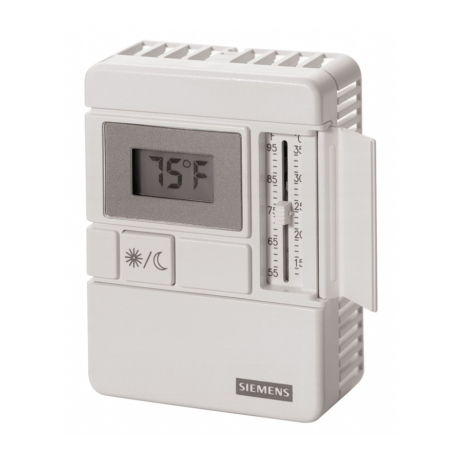
Figure 1. Room Temperature Sensor
(Shows All Options).
Document No. 540-742
January 5, 2012
Page 1 of 4
Advertisement

Related Manuals for Siemens 1000 series


Summary of Contents for Siemens 1000 series
- Page 1 Installation Instructions Document No. 540-742 January 5, 2012 Series 1000 Room Temperature Sensors, 10KΩ Thermistor (TEC and LTEC) Product Description Required Tools • Phillips size 1 or 2 screwdriver These sensors work with the Terminal Equipment ® Controller (TEC) and L compliant Terminal •...
-
Page 2: Mounting Information
Figure 4. plate. Pull about 3 inches (75 mm) of the cable through Terminating the RJ-11 the mounting hardware in the order shown. Connector. See Figure 3. Page 2 of 4 Siemens Industry, Inc. - Page 3 Over-tightening may cause the sensor base plate to crack or bend. Continue with Drywall Mounting (No Rough-in, Figure 5. LTEC Room Sensor Jumper Location. Typical), Steps 7 through 13. The installation is now complete. Siemens Industry, Inc. Page 3 of 4...
- Page 4 Echelon Corporation registered in the United States and ORKS other countries. Other product or company names mentioned herein may be the trademarks of their respective owners. © 2012 Siemens Industry, Inc. Siemens Industry, Inc. Your feedback is important to us. If you have Document No.