Table of Contents
Advertisement
®
OPERATOR'S MANUAL
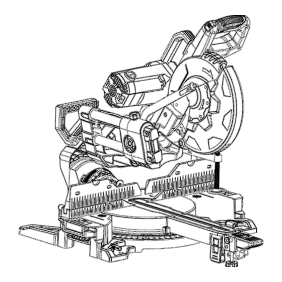
10" Compact-Slide Miter Saw
240-0021
OPERATOR'S MANUAL
For more information or to ask questions,
Call Toll-Free: (866) 902-9690
Monday-Friday between 8:30 AM and 5:00 PM ET
CAUTION: To Reduce The Risk Of Injury, User Must Read
And Understand Operator's Manual. Save These Instructions
For Future Reference.
Page 1
Advertisement
Table of Contents

Related Manuals for Master-force 240-0021


Summary of Contents for Master-force 240-0021
- Page 1 ® OPERATOR’S MANUAL 10” Compact-Slide Miter Saw 240-0021 OPERATOR’S MANUAL For more information or to ask questions, Call Toll-Free: (866) 902-9690 Monday-Friday between 8:30 AM and 5:00 PM ET CAUTION: To Reduce The Risk Of Injury, User Must Read And Understand Operator’s Manual. Save These Instructions For Future Reference.
-
Page 2: Table Of Contents
TABLE OF CONTENTS Safety symbols....................3 Safety instructions..................4 Electrical......................8 Laser....................... 9 Application..................... 10 Specifications and features................12 Assembly and adjustment.…………………...………………………....15 Operation ..................... 23 Maintenance....................30 Troubleshooting.................... 31 Warranty....................... 32 Page 2... -
Page 3: Safety Symbols
SAFETY SYMBOLS NOTE: Some of these following Proper interpretation of these symbols will symbols may be used on this tool. Please allow you to operate the tool better and study these and learn their meaning. safer. Symbol Name Designation / Explanation Read the Operator’s To reduce the risk of injury, user must read Operator’s Manual. -
Page 4: Safety Instructions
SAFETY INSTRUCTIONS WARNING! When using electric sharp edges. SECURE WORK. Use clamps or a vise tools basic safety precautions should to hold work when practical. It's safer always be followed to reduce the risk of than using your hand and it frees both fire, electric shock and personal injury hands to operate tool. - Page 5 Make workshop kid proof with Table 1.1 Minimum gauge for cord padlocks, master switches, or by removing starter keys. Tool’s Ampere Volts Total Length of Cord in Rating Feet Don’t force tool. It will do the job better (120V circuit Cord Size in A.W.G.
- Page 6 When servicing, use only cut. Do not use blades with incorrect manufacturer approved replacement size holes. Never use blade washers or parts. blade bolts that are defective or Never reach around the saw blade. incorrect. Do not perform any operation free ...
-
Page 7: Electrical
Your risk from these exposures varies, duration of use, noise from this tool may depending on how often you do this type of contribute to hearing loss. All visitors and bystanders must work. To reduce your exposure to these wear the same safety equipment that chemicals: the operator of the saw wears. -
Page 8: Laser
LASER WARNING: LASER LIGHT. LASER shiny reflective surfaces are not suitable for laser use, because the reflective RADIATION. Avoid direct eye exposure. surface could reflect the beam back at Do not stare into the beam. Only turn the operator. the laser beam on when the laser will ... -
Page 9: Application
APPLICATION by the No-Hands Zone symbols inside FUNCTION DESCRIPTIONS the symbols on the miter table base. Non-Through Cut: Any cutting AND INTENDED USE operation where the blade does not extend completely through the thickness This miter saw has been designed for of the work piece. -
Page 10: Part List
APPLICATION PART LIST Carefully remove the miter saw from its packaging and check that the following parts are included (Fig. 1). FIG.1 A 1pc Miter saw D 1pc Work piece clamp B 1pc Dust bag E 1pc Operator’s Manual C 1pc Saw blade wrench for changing blade (6 mm hex key) WARNING If any parts are damaged or missing, do not operate this saw until the missing parts are replaced. -
Page 11: Specifications And Features
SPECIFICATIONS AND FEATURES Motor 120V, ~60Hz Rated current No load speed 4,600 RPM Blade diameter 10” Arbor size 5/8” Electrical brake Net weight 58 pounds Cutting Capacities (Inches) 0° Miter x 45° Miter x 0° Miter x 45° Miter x 0°... - Page 12 FIG. 2 SPECIFICATIONS AND FEATURES FIG. 3 Page 12...
- Page 13 SPECIFICATIONS AND FEATURES KNOW YOUR SLIDING COMPOUND MITER-LATCH BUTTON MITER SAW When pushing the miter latch button down, The safe use of this saw requires an it will release the miter table from pre-set understanding of the information on the index points.
-
Page 14: Assembly And Adjustment
ASSEMBLY AND ADJUSTMENT your back, and get help when UNPACKING necessary. Step 1: Set the saw head at miter 0°, bevel WARNING This saw is heavy, to 0° and tighten the miter detent and the avoid back injury when unpacking, bevel lock knob. -
Page 15: Saw Blade Wrench
ASSEMBLY AND ADJUSTMENT ADJUSTMENT LOCKING noted, secure the workbench to the LEVERS floor before operating. FIG. 5 The adjustment locking levers for sliding fence and extension support arms are designed to provide the needed leverage to lock and unlock the controls easily. These levers can be rotated and pulled out, and rotated back without controlling the adjustment and then pushed back in to... -
Page 16: Setting The Bevel Angle
ASSEMBLY AND ADJUSTMENT 3. Several cycles may be required to tilting down suddenly due to its own weight, lock the cutting head firmly. hold the saw arm in place with one hand when loosening the bevel-lock lever. Step 3: Make sure the angle detent pin is in To lock the cutting head FIG. - Page 17 ASSEMBLY AND ADJUSTMENT often used angles on this saw, these angles include: 0°, 15°, 22.5°, 31.6°, 45° MITER CONTROL left and right. The miter-latch button is ADJUSTMENT used for setting the often used angles (Fig. 13). WARNING Before performing any FIG.
-
Page 18: Setting The Cutting Depth
ASSEMBLY AND ADJUSTMENT SETTING THE CUTTING DEPTH USING THE LED WORK LIGHT WARNING Before performing any This miter saw is equipped with a LED assembly or adjustment, always work light on the left side of saw head (Fig. disconnect from power source. Failure 16), there is a switch on the main handle. - Page 19 ASSEMBLY AND ADJUSTMENT cannot be used. Support work piece USING THE WORK PIECE with your hand outside the “No Hands” CLAMP zone. Do not try to cut short pieces that cannot be clamped and cause your hand to be in the “No Hands” zone. WARNING In some operations, the clamp assembly may interfere with the FIG.
- Page 20 ASSEMBLY AND ADJUSTMENT shipping has influenced the settings, USING THE LENGTH STOP refer to specific procedures explained as following. There are 5 accuracy adjustments totally: WARNING Before performing any (1) Squaring the blade to the fence. assembly or adjustment, always (2) Squaring the blade to the table.
- Page 21 ASSEMBLY AND ADJUSTMENT combination Square’s head. (2) SQUARING THE BLADE TO NOTE: To correct angle accuracy of THE TABLE the blade to the miter table, either by squaring the blade to the table, or by WARNING Failure to unplug your adjusting the blade to the miter table saw could result in accidental starting 45°...
-
Page 22: Operation
ASSEMBLY AND ADJUSTMENT (5) MITER-ANGLE INDICATOR (Fig. 24). ADJUSTMENT Step 4: If the indicator is not pointing to 0°, WARNING Failure to unplug your loosen the miter-angle indicator screw and saw could result in accidental starting adjust the miter-angle indicator to the “0” causing serious injury. -
Page 23: Slide Cuts
OPERATION the “No-Hands Zone”, as marked on the moveable safety guard to make the cut. saw table, or at least 3.25” away from Step 9: After finishing the cut, release the blade. Never perform any cutting trigger and wait until blade comes to a operation “freehand”... -
Page 24: Miter Cuts
OPERATION Step 6: Plug the saw into a power source. Step 2: Set the bevel angle at 0° and turn Step 7: Squeeze On/Off trigger. Always the miter table to desired angle using allow the blade to reach full speed before either the miter-detent or the miter scale cutting. -
Page 25: Compound Miter Cuts
OPERATION NOTE: This tool has multi-slide bar piece and force itself toward you. of two sections. Each section can be WARNING Failure to unplug the saw locked/unlocked by the locking knob. could result in accidental start up, NOTE: When performing any bevel which may cause serious injury. -
Page 26: Cutting Warped Material
OPERATION knob. CUTTING WARPED MATERIAL Step 1: Unplug the saw. Step 2: Loosen the lock nut, rotate the depth stop adjustment bolt to the desired WARNING Never pull the saw toward cutting depth, and retighten the lock nut. you during a cut. The blade can Step 3: Place a proper spacer between the suddenly climb up on top of the work work piece and the fence. -
Page 27: Cutting Crown Molding
OPERATION CUTTING USA CROWN Step 4: Reduce splintering by taping the MOLDING cut area prior to making the cut. Step 5: Plug the saw into a power source. USA Crown molding has a high top rear Step 6: Carefully follow all instructions for spring angle (the section that fits flat applicable miter, bevel or compound cuts. -
Page 28: To Remove The Blade
OPERATION See the following table for correct angle settings and correct positioning of the crown molding on the miter table. Miter Setting Bevel Setting Type of Cut Inside corner - Left side 31.6° Right 33.9° Left 1. Position top of molding against fence. 2. -
Page 29: Maintenance
MAINTENANCE GENERAL MAINTENANCE 3) Storage WARNING Failure to unplug the saw After cleaning the miter saw thoroughly, could result in accidental start up, store the saw in a dry room allow the which may cause serious injury. motor to cool down beforehand. NOTE: Always wear gloves when Store the miter saw out the reach of handling or working near blade which... -
Page 30: Troubleshooting
TROUBLESHOOTING WARNING: Before performing any Please be aware that any improper repairs repair work, always unplug the saw and will also invalidate the warranty and wait until the cutting blade has come to additional costs may be incurred. a standstill. Use only manufacturer approved spare CAUTION: Improper repairs can parts. -
Page 31: Warranty
WARRANTY If, during normal use, this MASTERFORCE® power tool breaks or fails due to a defect in material or workmanship within three years from the date of original purchase, simply bring this tool and its sales receipt back to your nearest Menards® retail store for a free equivalent replacement within those three years. - Page 32 ® For more information or to ask questions, Call Toll-Free: (866) 902-9690 Monday-Friday between 8:30 AM and 5:00 PM ET ©2015 Menard, Inc, Eau Claire, WI 54703 06/2015 Page 32...
Need help?
Do you have a question about the 240-0021 and is the answer not in the manual?
Questions and answers