
Related Manuals for Takeuchi TB014


Summary of Contents for Takeuchi TB014
- Page 1 Compact Excavator TB014 TB016 Serial No. ¡TB014: 11410001~ ¡TB016: 11610001~ Book No. AC4E020 OPERA TOR’S MANUAL WARNING Read and understand these instructions. Failure to do so can cause injury or death.
- Page 2 Always store this manual near at hand preferably on the machine itself. If it should be lost or damaged, immediately order a new one from your Takeuchi dealer. When transferring ownership of this machine, be sure to provide this manual to the next owner.
- Page 3 It is your responsibility to observe all pertinent laws and regulations and to follow the manufacturer’s instructions on machine operation, inspection and maintenance. Virtually all accidents occur as the result of a failure to observe basic safety rules and precautions. An accident can often be avoided by recognizing potentially hazardous situations beforehand.
-
Page 4: Introduction
This manual describes operation, inspection and maintenance of the machine, as well as safety instructions to be heeded during these operations. If you have any questions about the machine, please contact a Takeuchi sales or service outlet. Manual storage compartment... - Page 5 MACHINE DESCRIPTlON Front, rear, Ieft and right This manual refers the front, rear, left and right of the machine as seen when sitting in the operator’s seat with the dozer blade visible to the front. Designated operations Use this machine primarily for the following operations: ¡...
-
Page 7: Table Of Contents
CONTENTS Introduction ........2 Machine Description ...... 3 Safety ..........7 Controls .........35 Operation ........61 Transport ........91 Maintenance ........95 Troubleshooting ......137 Specifications ......149 Options ........179 Index ..........205... - Page 9 SAFETY General Precautions ........8 Preparing Precautions ....... 12 Starting Precautions ........14 Operating Precautions ....... 16 Stopping Precautions ........ 23 Transporting Precautions ......24 Maintenance Precautions ......25 Safety Signs (Decals) ......... 32...
-
Page 10: Safety
SAFETY General Precautions Wear appropriate clothing and Observe all safety rules personal protective equipment ¡ Operation, inspection and maintenance of this machine must be performed only by a trained and qualified person. ¡ All rules, regulations, precautions and safety procedures must be understood and followed when performing operation, inspection and maintenance of this machine. -
Page 11: General Precautions
SAFETY General Precautions Provide a fire extinguisher and Use a signal person and flagman first aid kit Know and use the hand signals required for ¡ Know where a fire extinguisher and first particular jobs and make sure who has the aid kit are located and understand how to responsibility for signaling. - Page 12 SAFETY General Precautions Be sure to lock the safety lock Avoid fire and explosion hazards lever before leaving the operator’s seat Keep flames away from fuel, hydraulic fluid, oil, grease and antifreeze. Fuel is particularly ¡ Before leaving the operator’s seat, set the flammable and dangerous.
- Page 13 ¡ For clean up, use wet methods or a operation or service life. ¡ Takeuchi will not be held responsible for vacuum equipped with a high efficiency particulate air (HEPA) filter. any injuries, accidents or damage to its ¡...
-
Page 14: Preparing Precautions
SAFETY Preparing Precautions Know the working area Always keep the machine clean Before starting operation, know the working area to ensure safety. ¡ Check the topography and ground condition of the working area, or the structure of the building when working indoors, and take the necessary safety measures in dangerous spots. -
Page 15: Preparing Precautions
SAFETY Preparing Precautions Perform inspection and maintenance daily Failure to notice or repair machine irregularities or damage can lead to accidents. ¡ Before operating, perform the prescribed inspections and make repairs immediately should any irregularities be found. ¡ If a failure that causes loss of control such as steering, service brakes or engine occurs, stop the machine motion as quickly as possible, follow the shutdown... -
Page 16: Starting Precautions
SAFETY Starting Precautions Maintain three point contact Clear the area of other persons when mounting and dismounting before starting the machine ¡ Do not jump on or off the machine. Never Do not start the engine until you are sure it is attempt to mount or dismount a moving safe. -
Page 17: Starting Precautions
SAFETY Starting Precautions Starting with jumper cables In cold weather ¡ Be careful of slippery conditions on Use jumper cables only in the recommended manner. Improper use of jumper cables can freezing ground, steps and hand holds. ¡ In severe cold weather, do not touch any result in battery explosion or unexpected machine motion. -
Page 18: Operating Precautions
SAFETY Operating Precautions Check for safety in the Ensure good visibility surrounding area before starting ¡ When working in dark places, turn on the machine’s working lights and headlights and/or provide extra stationary lighting if necessary. ¡ When visibility is poor due to severe weather (fog, snow or rain), stop operating the machine and wait until conditions improves. -
Page 19: Operating Precautions
SAFETY Operating Precautions Check the position of the Travel safety undercarriage (tracks) before traveling (12 to 16 in.) ¡Travel with the dozer blade up, the hoe attachment folded as shown on the Before operating the travel levers, check to diagram, and the bucket raised 30 to 40 make sure that the dozer blade is to the front cm (12 to 16 in.) from the ground. - Page 20 SAFETY Operating Precautions Cautions on traveling on slopes When traveling on slopes or grades, be careful that the machine does not tip (roll) over or slide. ¡ Never exceed the machine’s stability capabilities (maximum gradeability - 25°, lateral tipping angle - 10°). Also note that when actual working area conditions are ¡...
- Page 21 SAFETY Operating Precautions ¡Always contact the nearest electric utility Insure driver safety before and determine jointly what specific loading trucks precautions must be taken to insure safety. ¡Consider all lines to be power lines and treat all power lines as energized even though it is known or believed that the power is shut off and the line is visibly grounded.
- Page 22 SAFETY Operating Precautions • The ground is weak after rain or Watch out for hazardous working explosions. conditions • The ground is also unstable on banks and near dugout trenches. ¡ Never undercut a high bank. Be particularly alert for the possibility of a Operating on slopes is cave-in.
- Page 23 SAFETY Operating Precautions Never slew (swing) sideways with Excavators are not designed for excessive weights lifting loads The machine can tip over more easily in the The machine is specifically designed for lateral direction than in the longitudinal excavation work and has no safety devices direction.
- Page 24 SAFETY Operating Precautions Danger of flying objects Cautions on Towing This machine is not equipped with protective guards to protect the operator from flying objects. Do not use the machine in places where there are risks of the operator being hit by flying objects.
-
Page 25: Stopping Precautions
SAFETY Stopping Precautions Park safely E3A4901 ¡ Park the machine on firm, level ground and apply the parking device. ¡ When parking on streets, use barriers, caution signs, lights, etc., so that the machine can easily be seen even at night to avoid collision with other vehicles. -
Page 26: Transporting Precautions
SAFETY Transporting Precautions Load and unload the machine Hoist the machine safely safely ¡ Know and use correct crane signals. ¡ Inspect the hoisting equipment daily for damaged or missing parts. ¡ Keep all other persons out of the area Fasten to the suspension fitting when hoisting. - Page 27 SAFETY Maintenance Precautions Attach a “DO NOT OPERATE” tag Anti-explosive lighting Severe injury could result if an unauthorized person should start the engine or touch controls during inspection or maintenance. ¡ Stop the engine and remove the key before performing maintenance. ¡...
-
Page 28: Maintenance Precautions
SAFETY Maintenance Precautions Stop the engine before Prepare the work area performing maintenance ¡ Select a firm, level work area. Make sure ¡ Avoid lubrication or mechanical there is adequate light and, if indoors, adjustments with the machine in motion ventilation. - Page 29 SAFETY Maintenance Precautions Securely block the machine or Secure the engine hood or cover any component that may fall when opened Be sure to secure the engine hood or cover when opening it. Do not open the engine hood or cover on slopes or in strong wind. Place heavy objects in a stable position ¡...
- Page 30 SAFETY Maintenance Precautions Be careful with hot and Use caution when fueling pressurized components ¡ Do not smoke or permit open flames while Stop the engine and allow the machine to fueling or near fueling operations. cool down before performing inspection and ¡...
- Page 31 SAFETY Maintenance Precautions Be careful with fluids under Release all pressure before pressure working on the hydraulic system Pressure can be maintained in the hydraulic Oil may spurt out if caps or filters are removed circuit long after the engine has been shut or pipes disconnected before releasing the down.
- Page 32 SAFETY Maintenance Precautions ¡ Always unfasten the negative (–) battery Disconnect the battery cable first when disconnecting the battery cable. Always connect the negative (–) battery cable last when fastening the battery cable. ¡ Loose battery terminals may result in sparks.
- Page 33 Have a Takeuchi service agent repair welding cracks or other damage Ask a Takeuchi service agent to repair any welding problems which are detected. If not feasible, make sure the welding is done by a qualified person in a properly equipped workplace.
- Page 34 SAFETY Safety Signs (Decals) The following safety signs (decals) have been placed on your machine in the areas indicated. They are intended for the personal safety of you, and those working with you. Please take this manual, walk around your machine and note the content and location of these safety signs. Review these signs and the operating instructions in this manual with your machine operators.
-
Page 35: Safety Signs (Decals)
SAFETY Safety Signs (Decals) 1. No.03593-06500 5. No.05693-21980 WARNING WARNING D O N OT e n t e r i n t o Engine may be HOT sw i n g i n g a r e a 05693-21980 6. No.03993-00500 2. - Page 36 SAFETY Safety Signs (Decals) 10. No.03393-75050 12. No.03593-06700 Hydraulic oil CAUTION HYDRAULIC TANK MUST REMAIN PRESSURIZED TO AVOID DAMAGE TO PUMPS. 03393-75050 11. No.03593-06600 Diesel Fuel 13. No.03593-54028 Noise Outside the Cab This value indicates the noise level outside the machine and refers to the noise perceived by the persons who are in the vicinity of the work area.
- Page 37 CONTROLS Names of Components ......36 Doors and Covers ........38 Seat and Seat Belt ........43 Instrument Panel ........45 Switches ............. 47 Levers and Pedals ........49 Accessories ..........53...
-
Page 38: Controls
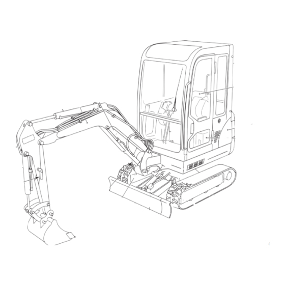
CONTROLS Names of Components C4B001 Upperstructure Undercarriage Working equipment 1. Cab 6. Crawler belt 11. Bucket 2. Seat 7. Idler 12. Bucket cylinder 3. Engine hood 8. Track roller 13. Arm 4. Fuel tank 9. Shoe slide 14. Arm cylinder 5. - Page 39 CONTROLS Names of Components 1. Instrument panel 10. Left operating lever 2. Starter switch 11. Right operating lever 3. Light switch 12. Pedal lock 4. Horn switch 13. Boom swing pedal 5. Travel speed switch 14. Travel lever 6. Wiper switch (Cab) 15.
-
Page 40: Doors And Covers
CONTROLS Doors and Covers To open the door from inside the cab, push Starter Key the lever (2) to the front. 3. Open the door fully and press it against the cab to lock it in place. Closing E4B003 The starter key is used not only to start and stop the engine, but also to lock and unlock the cab door, engine hood, fuel cap, manual storage C4C002... -
Page 41: Doors And Covers
CONTROLS Doors and Covers 2. Set the safety lock lever to the locked Lower Front Window (Cab) position. 3. Pull the left and right lock pins (1) to the Removing inside then turn them to the locked position to unlock the front window. If the lock pins (1) are partially sticking out they may cause damage. - Page 42 CONTROLS Doors and Covers Side Window (Cab) Maintenance Cover WARNING ¡ ¡ ¡ ¡ ¡ Before opening the maintenance cover, set the safety lock lever securely to the locked position and stop the engine. ¡ ¡ ¡ ¡ ¡ When opening the maintenance cover, open it firmly to the locked position.
- Page 43 CONTROLS Doors and Covers Fuse Box Tool Box The fuses protect the electrical system from excess currents. C4B006 1. Insert the starter key and turn it C4B029 counterclockwise to unlock the tool box. 2. After using tools, store them back in the Opening tool box.
- Page 44 CONTROLS Doors and Covers 2. Close the engine hood and press it down Engine Hood until a click is heard at the front. 3. Insert the starter key and turn it clockwise WARNING to lock the engine hood. ¡ ¡ ¡ ¡ ¡ Before opening the engine hood, be sure to stop the engine.
-
Page 45: Seat And Seat Belt
CONTROLS Seat and Seat Belt Seat Seat Belt WARNING CAUTION Adjust, secure and latch the operator’s Always fasten the seat belt securely seat. before starting the engine. Fastening the seat belt 1. Adjust the seat to the optimum position for operating, raise your torso, and sit back firmly into the seat. - Page 46 CONTROLS Seat and Seat Belt Releasing the seat belt C4C012 1. To remove the seat belt, simply press the button (D) located on the buckle. Once the belt has been removed, reinsert the tongue plate into the buckle so that seat belt remains in full view.
-
Page 47: Instrument Panel
For the TB014, the warning lamp lights but no 4. Coolant Temperature Warning Lamp alarm is sounded. This lamp flashes or lights Refer to page 143 “Troubleshooting”. - Page 48 CONTROLS Instrument Panel Indicators Meters 5. Glow Lamp 7. Hour Meter (TB014) < TB014 > This displays the total This lamp lights while the engine running time in key is at the PREHEAT hours. C4B016 position. The rightmost digit indicates C4B013 <...
-
Page 49: Switches
CONTROLS Switches Starter Switch Horn Switch PREHEAT START E4B010 IMPORTANT: Do not repeatedly switch Press the switch on the right operating lever the key from OFF to ON and ON to OFF to blow the horn. over a short period. Doing so will cause engine breakdown. - Page 50 CONTROLS Switches Light Switch Wiper Switch (Cab) IMPORTANT: If no washer fluid is discharged, do not operate the washer. Doing so may damage the pump. IMPORTANT: Operating the wiper with no moisture on the windshield will scratch the glass. Apply water or washer fluid when operating the wiper.
-
Page 51: Levers And Pedals
CONTROLS Levers and Pedals Safety Lock Lever WARNING ¡ ¡ ¡ ¡ ¡ Before leaving the operator’s seat, set the safety lock lever securely to the lock position and stop the engine. If any controls should be touched accidentally when the safety lock lever is lowered, the machine will move suddenly, and cause serious injury or death. - Page 52 CONTROLS Levers and Pedals Throttle Lever Operating Levers WARNING ¡ ¡ ¡ ¡ ¡ Be careful to check which pattern of lever control arrangement you are operating with before beginning operations. ¡ ¡ ¡ ¡ ¡ The explanations in this manual are for the ISO pattern.
- Page 53 CONTROLS Levers and Pedals Blade Lever Selector Lever (TB016) C4B023 Use this lever to operate the dozer blade and Use this lever when changing the crawler for TB016 switch the crawler width. width. This lever switches the operation of (A) ..Blade up/narrow crawler width the blade and span cylinders.
- Page 54 CONTROLS Levers and Pedals Boom Swing Pedal Use this pedal to operate the boom swing. (A) ..Boom swing right (B) ..Boom swing left Auxiliary Pedal This pedal controls the flow of the oil in the auxiliary hydraulic circuit. (A) ..
-
Page 55: Accessories
Cooling water could leak when the valve II ..Heater fan rotates at high speed. is set at a halfway position. Heater / Defroster Switch 〈 TB014 〉 〈 TB016 〉 C4C015 1. Park on a flat surface and stop the engine. - Page 56 CONTROLS Accessories Connecting the Hydraulic Circuits Auxiliary Hydraulic Lines To connect the attachment hydraulic lines, use the following procedures: WARNING 1. Move the auxiliary pedal several times to relieve pressure on the lines. Oil may spurt out if caps or filters are 2.
- Page 57 CONTROLS Accessories Radio (Cab Type) Operating precautions ¡ To ensure safe operation of the machine, always be sure to keep the volume of the radio down to a level where you can easily hear sounds from outside the machine. ¡ Do not keep the radio playing for long periods of time with the engine stopped. Doing so will drain the battery of its charge and make it difficult or impossible to restart the engine.
- Page 58 CONTROLS Accessories (4) Program indicators (8) Fast-forward / rewind / program Indicates tape direction. When s lamp is on. changeover button Upper side of a tape is playback, t indicates playback of lower side. Fast-forward (5) Display MTL LOUD ST MTL LOUD ST L2C003 Fast-rewind / Stop...
- Page 59 CONTROLS Accessories (12) Band select switch Pressing the “BAND” button changes over between FM1, FM2 and AM (MW) bands. The display indicates the receiving band name and frequency. (13) Metal switch Press the “MTL” (5) button before playing a C4C022 metal or CrO tape.
- Page 60 CONTROLS Accessories (15) DISP (Time/Frequency) button External Power Sockets (for EU) This system is equipped with a clock which can show the accurate time. Even if the radio WARNING is off, the clock still shows the time. Only use applicable electric products with (16) PS / AS switch these sockets.
- Page 61 CONTROLS Accessories Interior Light (Cab) IMPORTANT: The battery capacity will decrease if the interior light is left on for long periods of time the engine stopped. Turn the lamp off when leaving the machine. C4C025 1. Press the lighter in. 2.
- Page 63 OPERATION Before Starting Operation ......62 Starting and Stopping the Engine ..... 63 Machine Operation ........66 Operating Procedures ....... 77 Parking the Machine ........85 Handling in Cold Weather ......86 Handling Rubber Crawlers ......87...
-
Page 64: Operation
OPERATION Before Starting Operation Mounting and Dismounting Walk-Around Inspection Perform the walk-around inspections once WARNING a day before starting the engine the first time that day. ¡ ¡ ¡ ¡ ¡ Do not jump on or off the machine. Perform the inspections as described under Never attempt to mount or dismount a “Maintenance - Walk-Around Inspection”... -
Page 65: Starting And Stopping The Engine
(3) flash, and C4B018 the other lamps turn off. 3. Check that the safety lock lever is in the TB014: Warning lamps (2) and (3) light locked position. and no alarm is sounded. ¡Turn the light switch to check that the boom light, tail lamp and meter light turn ¡Check the fuel level. - Page 66 START E4D060 2. Turn the key to the PREHEAT position and hold it there for 5 seconds. < TB014 > D5D014E The glow lamp is not automatically turns off. 1. Pull the throttle lever to the middle position. < TB016 >...
- Page 67 OPERATION Starting and Stopping the Engine Warming Up the Engine Stopping the Engine IMPORTANT: Avoid racing the engine IMPORTANT: Do not stop the engine until it is warmed up. suddenly when operating with heavy Do not warm up the engine for long loads or at maximum speed.
-
Page 68: Machine Operation
OPERATION Machine Operation Lever Pattern (ISO Pattern) WARNING ¡ ¡ ¡ ¡ ¡ Be careful to check which pattern of lever control arrangement you are operating with before beginning operations. ¡ ¡ ¡ ¡ ¡ The explanations in this manual are for the ISO pattern. 〈... - Page 69 OPERATION Machine Operation Lever Pattern (JCB Pattern) WARNING ¡ ¡ ¡ ¡ ¡ Be careful to check which pattern of lever control arrangement you are operating with before beginning operations. ¡ ¡ ¡ ¡ ¡ The explanations in this manual are for the ISO pattern. 〈...
- Page 70 OPERATION Machine Operation Warming Up the Machine (Hydraulic Oil) WARNING Operating the working equipment without warming up the machine (hydraulic oil) is dangerous, as response will be slow G4D005 and the equipment may move in 3. Extend and retract each of the cylinders unexpected ways.
- Page 71 With this excavator the crawler width can be changed. Normally use with extended TB014 TB016 á ñ á ñ...
- Page 72 OPERATION Machine Operation IMPORTANT: Always lift the body before Changing the Dozer blade width changing the crawler width. Failure to do so can result in damage to the travel frame and spanner cylinder. C4D019 1. Loosen bolts (1) and remove plate (2). 2.
- Page 73 OPERATION Machine Operation Traveling Forward and Backward Operating the Travel Levers WARNING ¡ ¡ ¡ ¡ ¡ Never allow anyone to enter the slew (swing) radius and machine path. ¡ ¡ ¡ ¡ ¡ Signal your intention to move by sounding the horn.
- Page 74 OPERATION Machine Operation Pivot Turn Neutral Neutral Neutral E4D015 When the dozer blade is in front of the E4D017 operator’s seat: Turning to the left when stopped: a To move forward: aTo turn forward to the left: Tilt the levers forward. Tilt the right lever forward.
- Page 75 OPERATION Machine Operation Spin Turn Stopping Travel WARNING ¡ ¡ ¡ ¡ ¡ Park the machine on firm, level ground Neutral and apply the parking device. If you must park on a slope or incline, block the machine securely to prevent movement.
- Page 76 OPERATION Machine Operation Slewing Operating the Working Equipment WARNING WARNING Check the surrounding area for safety before slewing. ¡ ¡ ¡ ¡ ¡ Be careful to check which pattern of lever control arrangement you are operating with before beginning operations. ¡...
- Page 77 OPERATION Machine Operation Operating the Arm Operating the Boom Swing E4D023 C4D008 a To contract the arm: aTo swing left: Tilt the left operating lever backward. Press the left side of the pedal. e To extend the arm: eTo swing right: Tilt the left operating lever forward.
- Page 78 OPERATION Machine Operation When using a hydraulic breaker Operating the Auxiliary (1-way flow) Hydraulics Use this to operate a breaker, crusher or other attachment. D5D026 1. Make sure the auxiliary pedal is in the neutral position. 2. Loosen the lock nut (1). 3.
-
Page 79: Operating Procedures
OPERATION Operating Procedures Be Gentle on the Hydraulic Cylinders Prohibited Operations WARNING ¡ ¡ ¡ ¡ ¡ Do not operate on base rock (hard or soft). ¡ ¡ ¡ ¡ ¡ Do not slew (swing) while traveling. If you must operate the hoe attachment while traveling, operate at speeds slow E4D031 enough so you have complete control... - Page 80 OPERATION Operating Procedures Do not Perform Operations Using the Caution on Exposing the Dozer Blade to Machine’s Dropping Force Shocks E4D040 Hitting the dozer blade against rocks, etc., could damage the dozer blade or the blade cylinder. Caution on Folding the Hoe Attachment E4D033 Putting excessive strain on the machine will shorten its service life.
- Page 81 OPERATION Operating Procedures Pay Attention to the Dozer Blade when Cautions on Operating Digging Cautions on Traveling E4D0431 When digging deeply with the dozer blade E4A040 positioned at the front, be careful that the Traveling over obstacles (rocks, stumps, etc.) boom cylinder and bucket do not hit the dozer may subject the body to strong shocks and blade.
- Page 82 If the slew bearing Make sure the machine never faces or main body should get submerged, sideways with respect to the slope. contact a Takeuchi sales or service outlet for inspection.
- Page 83 OPERATION Operating Procedures Traveling Posture Braking when traveling down slopes Traveling up slopes Braking E4D045E When traveling down slopes, the brakes are When traveling up slopes at an angle of 15° applied automatically when the travel levers or greater, travel in the posture shown in the are returned to the neutral position.
- Page 84 OPERATION Operating Procedures Do not open the door while traveling on Getting Out of Mud slopes If the machine gets stuck in mud, use the procedure below to get it out. If one crawler is stuck E4D048 Opening the door while traveling on slopes is dangerous, as the force required to open and close the door changes abruptly.
- Page 85 OPERATION Operating Procedures Digging Side Ditches Operations Possible with this Machine Excavating 80 ~120 C4D015 Use the offset function to dig side ditches as shown in the diagram. E4D0501 1. Set the dozer blade on the side opposite Loading the side you want to dig on. 2.
- Page 86 OPERATION Operating Procedures Leveling E4D053 1. Bring the hoe attachment close to the body. 2. Gradually remove the dirt from the side of the mound. 3. Once the mound is low, remove the dirt from the top. If the load on the body is too heavy, adjust by raising or lowering the dozer blade.
-
Page 87: Parking The Machine
OPERATION Parking the Machine Inspection and Checks After Parking Stopping the Engine WARNING 1. Check for oil and water leakage and inspect the working equipment, covers and lower body. If any irregularities are found, repair. 2. Fill the fuel tank. Refer to page 109 “Checking the Fuel Level”. -
Page 88: Handling In Cold Weather
Inspect the battery. If the charge is low, After Cold Weather is Over contact a Takeuchi sales or service outlet to have the battery charged. Perform the following after cold weather is Refer to page 117 “Inspecting the Battery over: Fluid Level and Replenishing”. -
Page 89: Handling Rubber Crawlers
OPERATION Handling Rubber Crawlers Rubber crawlers have an inherent weakness due to their use of rubber. Be sure to heed the prohibitions and cautions below so as to prevent damage to the crawlers and crawler slippage. Prohibited Actions E4D057 Do not travel or operate the machine in the ¡Do not let fuel, oil, salt or chemical solvents following places: get on the crawlers. - Page 90 OPERATION Handling Rubber Crawlers ¡ When storing the rubber crawlers for long Cautions periods of time (3 months or more), do so indoors in a place not exposed to direct Heed the following cautions when operating sunlight or rain. the machine: L4D013 ¡Rubber crawler belts are not as stable as ¡...
- Page 91 OPERATION Handling Rubber Crawlers ¡ When climbing in reverse, do not change course at the point where the slope starts. ¡ Do not change directions when the crawler belts are slack as shown in the diagram. ¡ Avoid traveling with one crawler on a slope or projecting object and the other crawler on a flat surface (with the machine at a tilt of 10°...
- Page 93 TRANSPORT Loading and Unloading ......92 Hoisting the Machine ......... 93 Securing the Machine ........ 94 Cautions on Transporting ......94...
-
Page 94: Transport
TRANSPORT Loading and Unloading 1. Apply the truck’s parking brake and place WARNING stoppers against its tires. 2. Fasten the ramps securely to the truck bed The machine may roll or tip over or fall so that they will not come off. Set the while loading or unloading it. -
Page 95: Hoisting The Machine
TRANSPORT Hoisting the Machine Hoisting posture WARNING Lift Eye ¡ ¡ ¡ ¡ ¡ Know and use correct crane signals. ¡ ¡ ¡ ¡ ¡ Inspect the hoisting equipment daily for damaged or missing parts. ¡ ¡ ¡ ¡ ¡ Keep all other persons out of the area when hoisting. -
Page 96: Securing The Machine
TRANSPORT TRANSPORT Securing the Machine Cautions on Transporting After loading the machine in the designated position, secure it as described below. Transporting Posture Padding Wire rope E4F002 1. Lower the dozer blade. Cautions on Transporting 2. Fully extend the bucket and arm cylinders, then lower the boom. - Page 97 MAINTENANCE General ............96 Service Data ..........98 Important Parts ........102 Maintenance Chart ........103 Walk-Around Inspection ......105 Daily Inspection (Every 10 Hours) ... 107 After First 50 Hours (New Machines Only) ...... 112 Every 50 Hours ......... 115 Every 100 Hours ........
-
Page 98: Maintenance
Have inspection and maintenance as recommended in this manual. procedures not prescribed in this manual performed by a Takeuchi sales or service The inspection and maintenance items are outlet. divided according to the machine’s total operating time (inspection and maintenance Always keep the machine clean. - Page 99 If the sealing grooves of the surface serviced parts. ¡Operate all the operating levers and check of contact are damaged, consult a Takeuchi sales or service outlet. that the machine is operating properly. Seals and split pins Cautions on handling of battery cables ¡...
-
Page 100: Service Data
-22 -4 14 32 50 68 86 104 R R R R R (US. qt.) interval ° -30 -20 -10 0 10 20 30 40 Upper limit: TB014: 3.0 (3.2) Diesel SAE 5W-20 After first 50 TB016: 2.8 (3.0) Engine... - Page 101 Part No. Hydraulic oil return Element 15511-01300 After first 50 hrs. filter Every 500 hrs. Fuel filter Element < TB014 > Every 500 hrs. RA211-51281 < TB016 > 119810-55650 Engine oil filter Cartridge < TB014 > After first 50 hrs.
- Page 102 16901-00013 Spanner 19102-12083 13-17 <TB014> 10 Spanner 16900-01922 19-22 Spanner 19100-47082 14-17 <TB016> 11 Spanner 16909-00026 Socket wrench 19102-12084 19-22 <TB014> 12 Pliers 16905-00200 200mm Screwdriver 19102-12085 (+) (–) <TB014> 13 Grease gun 16910-60600 600cc Screwdriver 19100-06112 (+) (–) <TB016>...
- Page 103 ¡ Tightening torques when mounting plastic covers differ from the values on the table below. Consult a Takeuchi sales or service outlet. Tightening too strongly will break the cover. ¡ When replacing nuts and bolts, replace them with nuts and bolts of the same size and standards.
-
Page 104: Important Parts
If a hose clamp is deformed or cracked, replace it immediately. When replacing the important parts, please contact a Takeuchi sales or service outlet . Also check the hydraulic hoses other than the above important parts. If any abnormality is found in them, retighten them or replace them immediately. -
Page 105: Maintenance Chart
MAINTENANCE Maintenance Chart Maintenance Items See page Walk-Around Inspection Inspecting by opening the engine hood and covers Inspecting by walking around the machine Inspecting while sitting in the operator’s seat Daily Inspection (Every 10 Hours) Inspecting and replenishing the coolant Inspecting and replenishing the engine oil Inspecting the dust indicator Inspecting the water separator... - Page 106 MAINTENANCE Maintenance Chart Maintenance Items See page Every 250 Hours Inspecting and adjusting the fan belt Replacing the engine oil and oil filter Cleaning the air cleaner Cleaning the radiator fins and oil cooler fins Every 500 Hours Replacing the hydraulic oil return filter Replacing the fuel filter Every 1000 Hours Cleaning the engine cooling system...
-
Page 107: Walk-Around Inspection
MAINTENANCE Walk-Around Inspection Perform the following inspections once every day before starting the engine the first time. WARNING ¡ ¡ ¡ ¡ ¡ Before operating, perform the walk-around inspections and make repairs immediately should any irregularities be found. ¡ ¡ ¡ ¡ ¡ Be sure to secure the engine hood or cover when opening it. Do not open the engine hood or cover on slopes or in strong wind. - Page 108 MAINTENANCE Walk-Around Inspection Inspecting by Walking Around Inspecting While Sitting in the the Machine Operator’s Seat 4. Check lights for dirt, damage and burnt 13. Check the windshield for dirt or damage. out bulbs. 14. Check the seat and seat belt for dirt or 5.
-
Page 109: Daily Inspection (Every 10 Hours)
If the reserve tank is empty, inspect for fluid leakage, then inspect the radiator Inspection coolant level. If it is low, add water to the < TB014 > radiator first, then to the reserve tank. 3. Install the cap (2). < TB016 >... - Page 110 3 minutes, then stop it. 5. After about 10 minutes, inspect the oil Inspection level. < TB014 > Inspecting the Dust Indicator WARNING Stop the engine and allow the machine to cool down before performing < TB016 >...
- Page 111 ¡ ¡ ¡ ¡ ¡ Stop the engine in a well-ventilated < TB014 > place when adding fuel. ¡ ¡ ¡ ¡ ¡ Clean up spilled fuel immediately. ¡ ¡ ¡ ¡ ¡ Do not fill the fuel tank to capacity.
- Page 112 MAINTENANCE Daily Inspection (Every 10 Hours) Replenishing Inspecting the Hydraulic Oil Level and Replenishing WARNING Oil may spurt out if caps or filters are removed or pipes disconnected before releasing the pressure in the hydraulic system. C4G011 ¡ ¡ ¡ ¡ ¡ Gradually loosen the vent plug to 1.
- Page 113 MAINTENANCE Daily Inspection (Every 10 Hours) Lubricating the Working Equipment C4G0132 1. Set the machine to the lubrication posture shown in the diagram above, ground the working equipment, then stop the engine. 2. Use the grease gun to lubricate the grease nipples. 3.
-
Page 114: After First 50 Hours (New Machines Only)
MAINTENANCE After First 50 Hours (New Machines Only) 2. Loosen the bolt and remove the cover (8). Replacing the Hydraulic Oil (For cab models) Return Filter WARNING ¡ ¡ ¡ ¡ ¡ Stop the engine and allow the machine to cool down before performing maintenance. - Page 115 IMPORTANT: Check the spent oil. If it Replacing the Engine Oil and Oil contains large amounts of metal powder, Filter consult a Takeuchi sales or service outlet. WARNING < TB014 > Stop the engine and allow the machine to cool down before performing maintenance.
- Page 116 (6). tension (about 98 N or 22 lbs.). 6. Install the cover (1). Proper slack (A) : < TB014 > 5 to 7 mm (0.2 to 0.28 in.) < TB016 > 7 to 10 mm (0.28 to 0.4 in.) 3.
-
Page 117: Every 50 Hours
MAINTENANCE Every 50 Hours Inspecting and Adjusting the Crawler Tension WARNING ¡ ¡ ¡ ¡ ¡ If you must work beneath the raised machine or equipment, always use wood blocks, jack-stands or other rigid E4G0201 and stable supports. Never get under 2. - Page 118 MAINTENANCE Every 50 Hours Adjustment Lubricating the Slew Bearing Increasing the tension WARNING Do not slew while lubricating. Doing so is dangerous, as you may get caught in the machine. D5G025 1. Remove the cover (1). 2. Using the grease gun, insert grease through the grease nipple (3) in the grease discharge valve (2).
- Page 119 MAINTENANCE Every 50 Hours Lubricating the Slew Motor WARNING Pinion ¡ ¡ ¡ ¡ ¡ Do not fill the battery above the upper level. Doing so could cause the fluid to leak, contact and damage the skin, or cause parts to corrode. ¡...
- Page 120 MAINTENANCE Every 50 Hours ¡ If the fluid level can not be checked by Draining the Fuel Tank fluid level lines. WARNING ¡ ¡ ¡ ¡ ¡ Do not smoke or permit open flames while handling fuel or working on the fuel system.
-
Page 121: Every 100 Hours
¡ ¡ ¡ ¡ ¡ Clean up spilled fuel immediately. ¡ ¡ ¡ ¡ ¡ Clean up spilled fuel immediately. < TB014 > < TB014 > Refer to “Cleaning the Water Separator”. < TB016 > < TB016 >... -
Page 122: After First 250 Hours (New Machines Only)
MAINTENANCE After First 250 Hours (New Machines Only) Replacing the Travel Motor Gear WARNING ¡ ¡ ¡ ¡ ¡ Stop the engine and allow the machine to cool down before performing maintenance. • The travel motors are hot directly after the engine is stopped. Touching them will cause burns. -
Page 123: Every 250 Hours
MAINTENANCE Every 250 Hours 1. Open the engine hood. Inspecting and Adjusting the Fan Belt Refer to page 114 “Inspecting and Adjusting the Fan Belt”. Replacing the Engine Oil and Oil Filter Refer to page 113 “Replacing the Engine Oil and Oil Filter”. - Page 124 MAINTENANCE Every 250 Hours Cleaning the Radiator Fins and Oil Cooler Fins WARNING Wear required appropriate equipment such as safety glasses and filter mask when using compressed air, as metal E4G034 fragments or other objects can fly and 8. Light up the inside of the element with a cause serious personal injury.
-
Page 125: Every 500 Hours
< TB014 >. 4. Clean the case (4). 5. Assemble the new element and the indicator ring (6) < TB014 > in the case (4), then tighten the ring (3). 6. Open the cock (2) and bleed the air. Refer to page 141 “Bleeding the air from... -
Page 126: Every 1000 Hours
MAINTENANCE Every 1000 Hours 1. Open the engine hood. Cleaning the Engine Cooling < TB014 > System WARNING ¡ ¡ ¡ ¡ ¡ Stop the engine and allow the machine to cool down before performing maintenance. • The engine, muffler, radiator and... - Page 127 MAINTENANCE Every 1000 Hours 3. Place a pan for catching the spent coolant Replacing the Air Cleaner under the drain plug (4), then loosen the Element drain plug (4) and drain the coolant. 4. Tighten the drain plug (4), then add a little WARNING cleaning agent and tap water to the radiator until it is full.
- Page 128 Inspecting and Adjusting the at the top, then fasten it with the clamp Engine Valve Clearance (5). This operation requires experience. Have it performed by a Takeuchi sales or service outlet. Retightening the Engine Cylinder Head Bolts This operation requires experience. Have it...
-
Page 129: Every 2000 Hours
MAINTENANCE Every 2000 Hours Replacing the Hydraulic Oil and Cleaning the Suction Strainer WARNING ¡ ¡ ¡ ¡ ¡ Stop the engine and allow the machine to cool down before performing maintenance. C4G011 • The engine, hydraulic lines and many 3. - Page 130 Injection Timing inspection posture and inspect the level This operation requires experience. Have it once the temperature of the oil has performed by a Takeuchi sales or service dropped. outlet. Refer to page 110 “Inspecting the Hydraulic Oil Level and Replenishing”.
-
Page 131: When Required
MAINTENANCE When Required 1. Set the bucket with its bottom flat on a Replacing the Bucket Teeth block and the teeth sticking off the block. 2. Check that the bucket does not move, then WARNING set the safety lock lever to the locked position and stop the engine. - Page 132 MAINTENANCE When Required 2. Set the safety lock lever to the locked Replacing the Bucket position and stop the engine. 3. Remove the ring of the lock pin (1) and WARNING remove the lock pin. ¡ ¡ ¡ ¡ ¡ Before performing maintenance or repairs under the machine, set all working equipment against the ground or in the lowermost position.
- Page 133 MAINTENANCE When Required 3. Operate the cylinder, line up pin hole (B) Lubricating the Levers in the bucket with the pin hole in the link arm (6), and install the pin (2). WARNING Set the machine to the parking posture, stop the engine, remove the starter key and store it.
- Page 134 MAINTENANCE When Required Travel levers, blade lever and pedals Inspecting and Replenishing the Windshield Washer Fluid Use a windshield washer fluid designed specifically for motor vehicles. Follow the instructions including with the washer fluid. C4G033 1. Remove the floor mat (1). 2.
- Page 135 (3) Metal core Inspecting the Rubber Crawlers Repair or replace the rubber crawlers if their conditions are as described below. Consult a Takeuchi sales or service outlet about repairs or replacement. Rubber crawler Replace the crawler if the entire crawler is E4G064 stretched and cannot be adjusted.
- Page 136 MAINTENANCE When Required Replacing the Rubber Crawlers Direction of rotation WARNING ¡ ¡ ¡ ¡ ¡ If you must work beneath the raised machine or equipment, always use wood blocks, jack-stands or other rigid and stable supports. Never get under E4G067 the machine or working equipment if 3.
- Page 137 MAINTENANCE When Required 6. Check that the rubber crawler is securely engaged on the sprocket and idler. 7. Tighten the rubber crawler to the standard tension. Refer to page 115 “Inspecting and Adjusting the Crawler Tension”. 8. Install the other rubber crawler using the same procedure.
-
Page 138: Long-Term Storage
2. Inspect the battery and recharge it if Refer to page 124 “Cleaning the Engine necessary. Cooling System”. Have the battery charged by a Takeuchi 5. Use the grease gun to supply grease to sales or service outlet. the grease nipples. -
Page 139: Troubleshooting
TROUBLESHOOTING Symptoms that are not Malfunctions ..138 If the Engine Overheats ......139 If the Battery Goes Dead ......140 After the Fuel Runs Out ......141 If a Fuse Blows ......... 142 If a Warning Lamp Lights......143 Other Symptoms ........ -
Page 140: Symptoms That Are Not Malfunctions
TROUBLESHOOTING Symptoms that are not Malfunctions ¡ Performance decreases when an following symptoms malfunctions: attachment weighing more than a standard arm or bucket is mounted. E4J001 ¡ When the arm reaches the vertical position while contracting it while the engine is running at low speed, the contracting speed slows down momentarily. -
Page 141: If The Engine Overheats
C4J0011 ¡ TB016: An alarm is sounded and the coolant temperature warning lamp, engine emergency lamp flashes. ¡ TB014: The coolant temperature warning lamp lights. ¡ TB016: The water temperature gauge is in the red zone. ¡ The engine slows down and the force decreases. -
Page 142: If The Battery Goes Dead
TROUBLESHOOTING If the Battery Goes Dead The following symptoms indicate that the Connecting the jumper cables battery is dead: ¡ The starter motor does not turn or turns IMPORTANT: Set the starter keys of both weakly, and the engine does not start. the rescue vehicle and problem vehicle ¡... -
Page 143: After The Fuel Runs Out
(R) from the problem vehicle’s “+” terminal. leakage. Recharging Supplement: Air in the fuel system can Have a Takeuchi sales or service outlet make it difficult to start the engine and cause recharge batteries that have gone dead. engine problems. Also bleed the air when the fuel tank is emptied or air in the fuel system. -
Page 144: If A Fuse Blows
Cigarette lighter, system. Continued use may lead to fire. Wiper (cab), Consult a Takeuchi sales or service Travel alarm (option) outlet. Horn, Clock(radio), Interior light 1. Turn the starter key to the OFF position and stop the engine. -
Page 145: If A Warning Lamp Lights
Inspect the engine oil level. If the lamp is flashing or lit Engine oil even though the level is normal or if it continues flashing pressure or lights after oil is added, consult a Takeuchi sales or warning lamp service outlet. Refer to page 108 “Inspecting and Replenishing the Engine Oil”. -
Page 146: Other Symptoms
TROUBLESHOOTING Other Symptoms For symptoms not included on the table below or if the problem persists after the proper procedures have been taken, consult a Takeuchi sales or service outlet. Symptom Main cause Procedure ¡Insufficient grease on left ¡ Add grease. - Page 147 TROUBLESHOOTING Other Symptoms Symptom Main cause Procedure ¡ Insufficient hydraulic oil ¡Replenish to the prescribed Hydraulic oil temperature is too high level. Refer to page 109. ¡Insufficient fuel ¡ Add fuel. Starter motor turns but engine does not start Refer to page 109. ¡Air in fuel system ¡Bleed the air.
-
Page 148: To Lower The Boom
4. Check for safety and machine stability. This operation is dangerous and requires 5. Turn the set screw (2) back to its original experience. Have it performed by a Takeuchi position. sales or service outlet. 6. Gripping the set screw (2) with a... -
Page 149: Towing
TROUBLESHOOTING Towing WARNING When towing, selecting the wrong wire rope, inspecting improperly, or towing in the wrong way could lead to accidents resulting in serious injury or death. ¡ ¡ ¡ ¡ ¡ The wire rope breaking or coming detached could extremely dangerous. -
Page 151: Specifications
SPECIFICATIONS Main Specifications ......... 150 Machine Dimensions ....... 152 Operating Range ........156 Lifting Capacities ........165... - Page 152 SPECIFICATIONS Main Specifications TB014 Equipped with 830 mm (33 in.) Arm TYPE CANOPY MASS With rubber crawlers 1410 (3110) 1525 (3360) Machine mass kg (lb.) (not including operator) With steel crawlers 1460 (3220) 1575 (3470) PERFORMANCE Heaped 0.038 (1.33) Bucket capacity m (cu.ft.)
- Page 153 SPECIFICATIONS Main Specifications TB016 Equipped with 930 mm (37 in.) Arm TYPE CANOPY MASS With rubber crawlers 1500 (3310) 1615 (3560) Machine mass kg (lb.) (not including operator) With steel crawlers 1550 (3420) 1665 (3670) PERFORMANCE Heaped 0.038 (1.33) Bucket capacity m (cu.ft.) (standard bucket) Struck...
- Page 154 SPECIFICATIONS Machine Dimensions TB014 Equipped with Canopy and 830 mm (33 in.) Arm Units: mm (inches)
- Page 155 SPECIFICATIONS Machine Dimensions TB014 Equipped with Cab and 830 mm (33 in.) Arm Units: mm (inches)
- Page 156 SPECIFICATIONS Machine Dimensions TB016 Equipped with Canopy and 930 mm (37 in.) Arm Units: mm (inches) Units: mm (inches)
- Page 157 SPECIFICATIONS Machine Dimensions TB016 Equipped with Cab and 930 mm (37 in.) Arm Units: mm (inches) Units: mm (inches)
- Page 158 SPECIFICATIONS Operating Range TB014 Equipped with Canopy and 830 mm (33 in.) Arm Units: mm (inches) Units: mm (inches)
- Page 159 SPECIFICATIONS Operating Range TB014 Equipped with Cab and 830 mm (33 in.) Arm Units: mm (inches) Units: mm (inches)
- Page 160 SPECIFICATIONS Operating Range TB016 Equipped with Canopy and 930 mm (37 in.) Arm Units: mm (inches)
- Page 161 SPECIFICATIONS Operating Range TB016 Equipped with Cab and 930 mm (37 in.) Arm Units: mm (inches)
- Page 162 SPECIFICATIONS Operating Range TB014 Equipped with Canopy and 1040 mm (41 in.) Arm Units: mm (inches) Values are indicated in units of mm, inches in( ). Bucket offset 825(32.5) 575(22.6) Front slewing radius 1435(56.5) 2545(100.2) in Transport position 2520(99.2) 3660(144.1) Max. ground digging radius...
- Page 163 SPECIFICATIONS Operating Range TB014 Equipped with Cab and 1040 mm (41 in.) Arm Units: mm (inches) Values are indicated in units of mm, inches in( ). Bucket offset 880(34.6) 575(22.6) Front slewing radius 1490(58.7) 2545(100.2) in Transport position 2520(99.2) 3660(144.1) Max. ground digging radius...
- Page 164 SPECIFICATIONS Operating Range TB016 Equipped with Canopy and 1130 mm (44 in.) Arm Units: mm (inches) Values are indicated in units of mm, inches in( ). Bucket offset 575(22.6) 825(32.5) Front slewing radius 1435(56.5) 2665(104.9) in Transport position 2600(102.4) 3890(153.1) Max. ground digging radius 3990(157.1) Max.
- Page 165 SPECIFICATIONS Operating Range TB016 Equipped with Cab and 1130 mm (44 in.) Arm Units: mm (inches) Values are indicated in units of mm, inches in( ). Bucket offset 575(22.6) Front slewing radius 1520(59.8) 2665(104.9) in Transport position 2600(102.4) 3890(153.1) Max. ground digging radius 3990(175.1) Max.
-
Page 167: Lifting Capacities
SPECIFICATIONS Lifting Capacities Rated lift capacity chart ¡ The loads in the charts do not exceed 87% of hydraulic lift capacity or 75% of tipping load. ¡ Rated lift capacities limited by rated hydraulic lift capacity are identified by an asterisk(*) ¡... - Page 168 SPECIFICATIONS Lifting Capacities TB014 Equipped with 830 mm (33 in.) Arm C4K0091...
- Page 169 SPECIFICATIONS Lifting Capacities TB014 Equipped with 830 mm (33 in.) Arm C4K010...
- Page 170 SPECIFICATIONS Lifting Capacities TB016 Equipped with 930 mm (37 in.) Arm C4K0111...
- Page 171 SPECIFICATIONS Lifting Capacities TB016 Equipped with 930 mm (37 in.) Arm C4K012...
- Page 172 SPECIFICATIONS Lifting Capacities TB014 Equipped with 1040 mm (41 in.) Arm C4K0151...
- Page 173 SPECIFICATIONS Lifting Capacities TB014 Equipped with 1040 mm (41 in.) Arm C4K016...
- Page 174 SPECIFICATIONS Lifting Capacities TB016 Equipped with 1130 mm (44 in.) Arm C4K0131...
- Page 175 SPECIFICATIONS Lifting Capacities TB016 Equipped with 1130 mm (44 in.) Arm C4K014...
- Page 176 SPECIFICATIONS Lifting Capacities TB016 Equipped with Telescopic Arm (Fully Extended Arm) C4K0171...
- Page 177 SPECIFICATIONS Lifting Capacities TB016 Equipped with Telescopic Arm (Fully Extended Arm) C4K018...
- Page 178 SPECIFICATIONS Lifting Capacities TB016 Equipped with Telescopic Arm (Fully Retracted Arm) C4K0191...
- Page 179 SPECIFICATIONS Lifting Capacities TB016 Equipped with Telescopic Arm (Fully Retracted Arm) C4K020...
- Page 181 OPTIONS General Precautions ........ 180 Safety Signs (Decals) ....... 182 Biodegradable Oil ........184 Switching the Lever Pattern ....185 Attachment Combination Table ....186 Telescopic Arm ........187 Hydraulic Breaker ........192 Three-Hole Bucket ........194 High-back Seat ......... 197 Travel Alarm ..........
-
Page 182: Options
¡ ¡ ¡ ¡ ¡ Consult with a Takeuchi dealer before installing optional attachments. ¡ ¡ ¡ ¡ ¡ Do not use attachments that have not been approved by Takeuchi or a Takeuchi dealer. Doing so may compromise safety or adversely affect the machine’s operation or service life. - Page 183 OPTIONS General Precautions Precautions on Operating Attachments WARNING Long attachments reduce machine stability. When traveling down steep slopes or slewing on slopes, the machine may loose its balance and tip over. The following operations are particularly dangerous. Do not perform them. ¡...
-
Page 184: Safety Signs (Decals)
OPTIONS Safety Signs (Decals) Keep all safety signs clean and legible. Replace all missing, illegible or damaged safety and warning signs. There are other safety signs in addition to the ones listed here. Treat them in the same way. C4L0072... - Page 185 OPTIONS Safety Signs (Decals) 1. A-G selector valve 2. Check the lever pattern No.03593-32200 No.03593-32300 WARNING (ISO) Check what type of lever control arrangement you are operating with before beginning operations. 03593-32300 03593-32200 3. No.03393-22100 4. No.05693-53810 CAUTION Setting this switch to the “OFF” position will shut down all of the electrical circuits and the memory of the radio preset...
-
Page 186: Biodegradable Oil
The hydraulic oil system must be flushed as described below before supplying the biodegradable oil. This operation is dangerous and requires experience. Have it performed by a Takeuchi sales or service outlet. Flushing ¡... -
Page 187: Switching The Lever Pattern
OPTIONS Switching the Lever Pattern The operating pattern of the left and right operating levers can be changed. WARNING Before starting the engine, check the selector to see which operating pattern the left and right operating levers are set for. C4L004 Switching the Lever Pattern 4. -
Page 188: Attachment Combination Table
¡ ¡ ¡ ¡ ¡ Consult with a Takeuchi dealer before installing optional attachments. ¡ ¡ ¡ ¡ ¡ Do not use attachments that have not been approved by Takeuchi or a Takeuchi dealer. Doing so may compromise safety or adversely affect the machine’s operation or service life. -
Page 189: Telescopic Arm
OPTIONS Telescopic Arm Extending and Retracting the Caution on Using the Arm Use the auxiliary pedal to extend and retract the telescopic arm. OE3A331 ¡ The machine may loose balance and tip over when slewing or operating the C4B028 attachment on slopes. It is particularly dangerous to slew with the arm extended on the bucket full. - Page 190 OPTIONS Telescopic Arm OL1L100 OL1L070 ¡ Do not operate on base rock or hard soils, as doing so may shorten the arm’s service life. OL1L110 ¡ Do not put the arm under water. Also avoid moisture when storing. OL1L080 ¡ Do not change directions with machine lifted by pressing the bucket pressed against the ground.
- Page 191 Other parts may be damaged if the telescopic arm is used with such looseness. Contact a Takeuchi dealer for maintenance. Note that no maintenance is necessary other than the greasing described above.
- Page 192 OPTIONS Telescopic Arm Operating Ranges TB016 Canopy (Fully Extended Arm) Values are indicated in units of mm, inches in( ). Bucket offset 575(22.6) Front slewing radius 1525(60.0) 2580(101.6) 4140(163.0) Max. ground digging radius 4230(166.5) Max. digging radius...
- Page 193 OPTIONS Telescopic Arm Operating Ranges TB016 Canopy (Fully Retracted Arm) Values are indicated in units of mm, inches in( ). Bucket offset 575(22.6) Front slewing radius 1465(57.7) 2735(107.7) in Transport position 2490(98.0) 3705(145.9) Max. ground digging radius 3810(150.0) Max. digging radius...
-
Page 194: Hydraulic Breaker
For advice on selecting device, contact a ¡ Do not move the chisel while pounding. Takeuchi sales or service outlet. ¡ Do not pound continuously for over 30 seconds on the same surface. - Page 195 OPTIONS Hydraulic Breaker Replace the hydraulic oil regularly! ¡ When using a hydraulic breaker, the oil deteriorates quicker than during normal digging. Be sure to replace the hydraulic oil and return filter element. • Failure to replace these in time can lead to damage to the machine and breaker’s ¡...
-
Page 196: Three-Hole Bucket
OPTIONS Three-Hole Bucket Replacing the Bucket Teeth Replace the bucket teeth when the tooth points are worn, before the adapter is damaged. WARNING ¡ ¡ ¡ ¡ ¡ Before performing maintenance or OL1L170 repairs under the machine, set all working equipment against the ground or in the lowermost position. - Page 197 OPTIONS Three-Hole Bucket 3. Remove the key, then check that the Installation bucket is stable. OL1L220 1. Clean the adapter nose (3). OL1L200 If there is gravel or mud on the adapter 4. Place a rod against the locking pin (1) and nose, the tooth point will not go in all the knock the locking pin out by hammering way and the pin cannot be driven in.
- Page 198 OPTIONS Three-Hole Bucket OL1L250 4. Drive in the locking pin (1) with a hammer until it is flush with the tip of the tooth point (2) ear. OL1L260 OL1L270 5. The locking pin (1) is now driven in. The same procedure can be used to install the other tooth points.
-
Page 199: High-Back Seat
OPTIONS High-back Seat Seat WARNING Adjust, secure and latch the operator’s seat. 130kg 50kg (110 lbs.) (287 lbs.) C4L017 (C) Weight adjustment 1. Turn handle (3) to the front side and set it to indicate the weight of the person to operate the machine. - Page 200 OPTIONS High-back Seat Seat Belt CAUTION Always fasten the seat belt securely before starting the engine. Fastening the seat belt 1. Adjust the seat to the optimum position for operating, raise your torso, and sit back firmly into the seat. 2.
-
Page 201: Travel Alarm
If the fuse which has just been replaced Heater, Radio should blow again, there is a problem in the electrical system. This could cause Feed pump, Instrument panel fires. Contact a Takeuchi dealer. External power socket, Cigarette lighter, Wiper (cab), Travel alarm... -
Page 202: Radio (For Eu)
OPTIONS Radio (for EU) General operation ON/OFF AUDIO CONTEOL LOUD HI-POWER 35Wx4 / AUTO RADIO ACCESS TUNE/SEEK ー . P SCAN CLOCK B A N D ELECTRONIC AUDIO CONTROL FXC-315 C4C030 Turning the power on - - - - - (Min) + + + + + (Max) MODE Press the ON/OFF button 1. - Page 203 OPTIONS Radio (for EU) To cancel the beep tones ..... 1, 7, 8 Ejecting the tape ........4 Press the EJECT button 4 to eject a tape. The unit emits a beep tone to confirm that a function button has been pressed. To cancel The system will return to the audio source the function, follow the procedures below.
- Page 204 OPTIONS Radio (for EU) ¡ To scan programmed stations Storing preset stations ......3 The preset buttons 3 can be used to store See “Preset-Scan-Button operation”. 6 stations in each band (FM1, FM2, and MW) Supplement: If no station can be received, for convenient access to your favorite “- - -”...
- Page 205 OPTIONS Radio (for EU) Clock TUNE/SEEK ー . P SCAN CLOCK B A N D C4C033 Display mode change ......1 The display on the unit can be changed by pushing the button 1. Pushing button 1 alternates the display between time and radio/tape.
-
Page 206: Battery Switch
OPTIONS Battery Switch IMPORTANT: Never set this switch to the OFF (O) position while the engine is running. Doing so might cause damage to the electrical system. OFF (O) .. Switches off the electrical circuit. Be sure to set this switch to the OFF (O) position when storing the machine for a long period, or when performing maintenance of... - Page 207 INDEX...
-
Page 208: Index
INDEX A ~ D Accessories ..............53 Cab Door (Cab) ............38 After Cold Weather is Over ........86 Caution on Using the Arm ........187 After First 250 Hours (New Machines Only) .... 120 Caution on Using the Arm ........189 After First 50 Hours (New Machines Only) .... - Page 209 Handling of hoses ............28 Doors and Covers ............38 Handling Rubber Crawlers ......... 87 Draining the fuel tank ..........118 Have a Takeuchi service agent repair welding cracks or other damage ............31 Heater (Cab) .............. 53 High-back Seat ............197 Engine Hood ..............
- Page 210 INDEX I ~ O Inspecting the battery fluid level and replenishing ... 117 Lubricating the working equipment ......111 Inspecting the dust indicator ........108 Inspecting the engine fuel injection pressure and spray condition .............. 126 Inspecting the engine fuel injection timing ....128 Machine Description ............
- Page 211 INDEX O ~ S Operating Ranges TB016 Canopy Replace the hydraulic oil regularly! ......193 (Fully Retracted Arm) .......... 191 Replacing the air cleaner element ......125 Operating the Auxiliary Hydraulics ......76 Replacing the bucket ..........130 Operating the Travel Levers ........71 Replacing the bucket teeth ........
- Page 212 INDEX S ~ W Specifications ............149 Start the engine from the operator’s seat ....14 Use a signal person and flagman ........ 9 Starter Key ..............38 Use caution when fueling ........... 28 Starter Switch ............. 47 Use the correct tools ..........25 Starting and Stopping the Engine ......
- Page 213 First Published May 1998 No. 23105 Twenty-second Published April 2006 OPERATOR’S MANUAL TB014 TB030 Compact Excavator TB016 Edited and issued by TAKEUCHI MFG. CO., LTD. Printed in Japan by STATION M Co., Ltd.
- Page 214 CALIFORNIA Proposition 65 Warning Diesel engine exhaust and some of its constituents are known to the State of California to cause cancer, birth defects, and other reproductive harm. Battery posts, terminals and related accessories contain lead and lead compounds, chemicals known to the State of California to cause cancer and birth defects or other reproductive harm.
Need help?
Do you have a question about the TB014 and is the answer not in the manual?
Questions and answers