Table of Contents
Advertisement
Advertisement
Chapters
Table of Contents

Related Manuals for Suzuki VZR1800/BZ


Summary of Contents for Suzuki VZR1800/BZ
- Page 1 VZR1800/BZ OWNER’S MANUAL...
- Page 2 This manual should be considered a permanent part of the motorcycle and should remain with the motorcycle when resold or otherwise transferred to a new owner or operator. The manual contains important safety information and instructions which should be read carefully before operating the motorcycle.
- Page 3 Suzuki parts are WARNING manufactured of high quality materi- als and machined parts are finished Indicates a potential hazard that to close tolerances.
- Page 4 Your autho- rized Suzuki dealer has experienced technicians that are trained to provide your machine with the best possible service with the right tools and equip- ment.
-
Page 5: Table Of Contents
TABLE OF CONTENTS CONSUMER INFORMATION CONTROLS FUEL, OIL AND ENGINE COOLANT RECOMMENDATIONS BREAK-IN (RUNNING-IN) AND INSPECTION BEFORE RIDING RIDING TIPS INSPECTION AND MAINTENANCE TROUBLESHOOTING STORAGE PROCEDURE AND MOTORCYCLE CLEANING SPECIFICATIONS INDEX... -
Page 7: Consumer Information
CONSUMER INFORMATION ACCESSORY USE AND MOTORCYCLE LOADING ......... 1-2 MODIFICATION ....................1-4 SAFE RIDING RECOMMENDATION FOR MOTORCYCLE RIDERS ....1-4 LABELS ....................... 1-5 SERIAL NUMBER LOCATION ................1-6 NOISE CONTROL SYSTEM (AUSTRALIA ONLY) ..........1-6... -
Page 8: Accessory Use And Motorcycle Loading
The addition of unsuitable accesso- attachment hardware are rigidly ries can lead to unsafe operating con- mounted. ditions. It is not possible for Suzuki to • Inspect for proper ground clear- test each accessory on the market or ance and bank angle. Inspect that... -
Page 9: Controls
Loading Limit Loading Guidelines This motorcycle is primarily intended WARNING to carry small items when you are not riding with a passenger. Follow the guidelines below to carry a passenger Overloading or improper loading or cargo: can cause loss of motorcycle con- •... -
Page 10: Modification
MODIFICATION FAMILIARIZE YOURSELF WITH THE MOTORCYCLE Modification of the motorcycle, or Your riding skill and your mechanical removal of original equipment may knowledge form the foundation for render the vehicle unsafe or illegal. safe riding practices. We suggest that you practice riding your motorcycle in a non-traffic situation until you are SAFE RIDING RECOMMENDATION thoroughly familiar with your machine... -
Page 11: Labels
RIDE DEFENSIVELY LABELS The most common type of motorcycle Read and follow all the labels on the accident occurs when a car traveling motorcycle. Make sure you under- towards a motorcycle turns round cor- stand all of the labels. Do not remove ner in front of the motorcyclist. -
Page 12: Serial Number Location
They are also used to assist your TAMPERING WITH NOISE authorized Suzuki dealer when order- CONTROL SYSTEM PROHIBITED ing parts or referring to special ser- Owners are warned that the law may vice information. -
Page 13: Controls
CONTROLS LOCATION OF PARTS ..................2-2 KEY ........................2-5 IGNITION SWITCH ....................2-5 STEERING LOCK ....................2-6 INSTRUMENT PANEL ..................2-7 LEFT HANDLEBAR ................... 2-13 RIGHT HANDLEBAR ..................2-16 FUEL TANK CAP ....................2-18 GEARSHIFT LEVER ..................2-19 REAR BRAKE PEDAL ..................2-19 SEAT LOCK ....................... -
Page 14: Location Of Parts
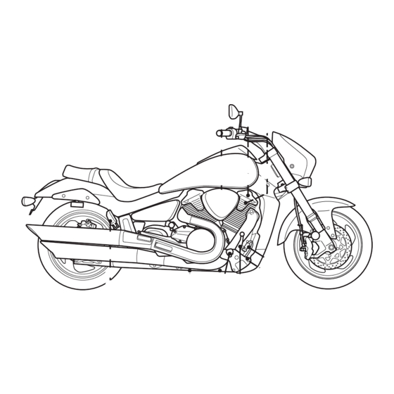
CONTROLS LOCATION OF PARTS 1 Clutch lever 2 Left handlebar switches 3 Instrument panel 4 Front brake fluid reservoir 5 Right handlebar switches 6 Throttle grip 7 Front brake lever 8 Fuel tank cap Canada, Australia, Middle East... - Page 15 9 Air cleaner 0 Spark plug A Ignition switch B Battery and tools C Main fuse and fuses D Seat lock E Helmet holder F Engine coolant reservoir G Gearshift lever H Footrests I Engine oil filler cap J Speed sensor K Side stand L Passenger footrests...
- Page 16 M Engine oil drain plug N Rear brake pedal O Engine oil filter P Rear brake light switch...
-
Page 17: Key
IGNITION SWITCH This motorcycle comes equipped with The ignition switch has 3 positions: a main ignition key and a spare one. Keep the spare key in a safe place. “OFF” POSITION All electrical circuits are cut off. The engine will not start. The key can be removed. -
Page 18: Steering Lock
If the motorcycle falls down, turn the ignition switch off immedi- Turn the handlebars all the way to the ately. Ask your authorized Suzuki left. Insert the ignition key into the dealer to inspect the motorcycle steering lock and turn it counterclock- for unseen damage. -
Page 19: Instrument Panel
TACHOMETER 1 INSTRUMENT PANEL The tachometer indicates the engine speed in revolutions per minute (r/ min). GEAR POSITION INDICATOR 2 The gear position indicator indicates gear position. This indicator displays “0” when the transmission is in neu- tral. NOTE: When the display indicates “CHEC”, the gear position indicator does not indicate a number but indi- cates “–”. - Page 20 Suzuki dealer. If the engine stalls, try restarting the If the fuel injection system fails, the red indicator light 7 comes on and engine after turning the ignition the display D indicates “FI”...
- Page 21 If the display still indicates “CHEC” does not go out, have your autho- after checking the above items, rized Suzuki dealer or a qualified inspect the ignition fuse and the con- mechanic inspect your motorcy- nection of the lead wire couplers.
- Page 22 CLOCK/FUEL METER A The display in the speedometer has two functions, clock and fuel meter. Clock The clock has a 12-hour display. Fol- low the procedure below to adjust the clock. 1. Push the buttons, SEL B and ADJ C, simultaneously for 2 sec- SPEEDOMETER 0 onds until the hour display blinks.
- Page 23 Fuel meter “” The fuel meter indicates the amount Approximately Approximately Fuel tank Full 1.5 L 4.0 L of fuel remaining in the fuel tank. The Blink fuel meter displays all 5 segments Fuel gauge when the fuel tank is full. The mark Blink Blink blinks when the fuel level drops below...
- Page 24 To change the display, push the SEL button B. The display changes in the order below. Odometer TRIP1 Trip meter 1 ODOMETER/TRIP METER D This display has three functions; TRIP 2 odometer and two trip meters. When the ignition switch is turned to the “ON”...
-
Page 25: Left Handlebar
Trip meters LEFT HANDLEBAR The two trip meters are resettable odometers. They can register two kinds of distances at the same time. For instance, trip meter 1 can register the trip distance and trip meter 2 can register the distance between fuel stops. - Page 26 NOTICE Holding dimmer switch between the “” and “” posi- tion will light both the high and low headlight beam. This improper operation can damage the motor- cycle’s headlight. Use the dimmer switch to select only the “” or “” position. DIMMER SWITCH 3 “”...
- Page 27 HORN SWITCH “” 5 TURN SIGNAL LIGHT SWITCH “” 4 Press the switch to sound the horn. Moving the switch to the “” position will flash the left turn signal. Moving HAZARD WARNING SWITCH “” the switch to the “” position will flash the right turn signal.
-
Page 28: Right Handlebar
RIGHT HANDLEBAR Front brake lever adjustment ENGINE STOP SWITCH 1 The distance between the throttle grip and the front brake lever is adjustable “” position to 5 positions. To change the position, The ignition circuit is off. The engine push the brake lever forward and turn cannot start or run. - Page 29 THROTTLE GRIP 4 ELECTRIC STARTER SWITCH “” Engine speed is controlled by the This switch is used for operating the position of the throttle grip. Turn it starter motor. With the ignition switch toward you to increase engine speed. in the “ON” position, the engine stop Turn it away from you to decrease switch in “”, the clutch disengaged, engine speed.
-
Page 30: Fuel Tank Cap
FUEL TANK CAP 1 Fuel level 2 Filler neck WARNING To open the fuel tank cap, insert the ignition key into the lock and turn it If you overfill the fuel tank, fuel clockwise. With the key inserted, lift may overflow when it expands due the cap up with key. -
Page 31: Gearshift Lever
GEARSHIFT LEVER REAR BRAKE PEDAL This motorcycle has a 5-speed trans- Depressing the rear brake pedal will mission which operates as shown. To apply the rear brake. The brake light shift properly, squeeze the clutch will come on when the rear brake is lever and close the throttle at the operated. -
Page 32: Seat Lock
SEAT LOCK To reinstall the seat, slide the seat hook into the seat hook retainer and 1. The seat lock is located under the push down firmly until the seat snaps left frame cover. To remove the into the locked position. seat, insert the ignition key into the lock and turn it clockwise. -
Page 33: Helmet Holder
HELMET HOLDER SIDE STAND The helmet holder is located on the This motorcycle is equipped with a left side below the rear seat. Insert side stand to support the motorcycle the key and turn it clockwise to open when parking. An interlock system is the latch. -
Page 34: Suspension Adjustment
SUSPENSION ADJUSTMENT WARNING REAR SUSPENSION Spring Pre-load Adjustment Riding with the side stand incom- The rear suspension spring pre-load pletely retracted can result in an is adjustable to compensate for the accident when you turn left. rider, load, riding style and road con- ditions. - Page 35 • Keep away from fire and heat. • Read owner’s manual for more information. NOTE: Ask your Suzuki dealer to dis- pose of the rear suspension unit. 2. Twist the spring tension ring to the desired position with an adjuster.
-
Page 36: Seat Tail Cover
SEAT TAIL COVER A seat tail cover for solo riding can be attached motorcycle. replace the rear seat with the seat tail cover, follow the procedure below. 1. Remove the front seat by referring to the SEAT LOCK section. 2. Remove the bolts 1. 3. -
Page 37: Fuel, Oil And Engine Coolant Recommendations
FUEL, OIL AND ENGINE COOLANT RECOMMENDATIONS FUEL OCTANE RATING ..................3-2 OXYGENATED FUEL RECOMMENDATION ............3-2 ENGINE OIL ......................3-4 FINAL GEAR OIL ....................3-5 COOLANT ......................3-5... -
Page 38: Fuel Octane Rating
Fuels containing 5% or less methanol another. If the situation will not be (wood alcohol) may be suitable for improved by changing, consult use in your motorcycle if they contain your Suzuki dealer for its inspec- co-solvents and corrosion inhibitors. tion. - Page 39 Suzuki and may not be covered under the Be careful not to spill any fuel New Vehicle Limited Warranty or the when filling the fuel tank.
-
Page 40: Engine Oil
ENGINE OIL JASO T903 The JASO T903 standard is an index Use Suzuki genuine engine oil or to select engine oils for 4-stroke equivalent. If Suzuki genuine engine motorcycle and ATV engines. Motor- oil is not available, select a proper... -
Page 41: Final Gear Oil
Energy Conserving COOLANT Suzuki does not recommend the use Use “SUZUKI SUPER LONG LIFE “ENERGY CONSERVING” COOLANT” or “SUZUKI LONG LIFE “RESOURCE CONSERVING” oils. COOLANT”. “SUZUKI SUPER Some engine oils which have an API LONG LIFE COOLANT” classification of SH or higher have an “SUZUKI LONG LIFE COOLANT”... - Page 42 Required amount of water/coolant SUZUKI SUPER LONG LIFE Solution capacity (total): 2700 ml COOLANT (Blue) (2.9/2.4 US/Imp. qt) “SUZUKI SUPER LONG LIFE COOL- ANT” is pre-mixed to the proper ratio. 1350 ml Water (1.4/1.2 US/Imp. qt) Add only “SUZUKI SUPER LONG LIFE COOLANT”...
-
Page 43: Break-In (Running-In) And Inspection Before Riding
BREAK-IN (RUNNING-IN) AND INSPECTION BEFORE RIDING MAXIMUM ENGINE SPEED RECOMMENDATION ..........4-2 VARY THE ENGINE SPEED ................4-2 BREAKING IN THE NEW TIRE ................4-2 AVOID CONSTANT LOW SPEED ..............4-2 ALLOW THE ENGINE OIL TO CIRCULATE BEFORE RIDING ......4-3 OBSERVE YOUR FIRST AND MOST CRITICAL SERVICE ...... - Page 44 160 km (100 miles) before attempting mum life and performance from your maximum performance. Avoid hard new Suzuki. The following guidelines acceleration, hard cornering, and explain proper break-in procedures. hard braking for the first 160 km (100 miles).
- Page 45 ALLOW THE ENGINE OIL TO INSPECTION BEFORE RIDING CIRCULATE BEFORE RIDING WARNING Allow sufficient idling time after warm or cold engine startup before applying Failure to inspect your motorcy- load or revving the engine. This cle before riding and to properly allows time for the lubricating oil to maintain your...
- Page 46 Before riding the motorcycle, be sure Tires • Correct pressure to check the following items. Never ( 6-35) • Adequate tread depth underestimate importance • No cracks or cut these checks. Perform all of them Engine oil Correct level before riding the machine. (...
-
Page 47: Riding Tips
RIDING TIPS STARTING THE ENGINE ..................5-2 STARTING OFF ....................5-3 USING THE TRANSMISSION ................5-4 RIDING ON HILLS ....................5-5 STOPPING AND PARKING ................5-5... -
Page 48: Starting The Engine
When the engine is warm: RIDING TIPS Close the throttle completely and push the electric starter switch. STARTING THE ENGINE Before attempting to start the engine When the engine is hard to start: make sure: Open the throttle 1/8 to 1/4 turn and •... -
Page 49: Starting Off
STARTING OFF After moving the side stand to the fully up position, squeeze the clutch WARNING lever in and pause momentarily. Engage first gear by depressing the gearshift lever downward. Turn the Riding excessive speeds increases your chances of losing throttle grip a little toward you and at the same time release the clutch lever control of the motorcycle, which... -
Page 50: Using The Transmission
USING THE TRANSMISSION WARNING The transmission is provided to keep the engine operating smoothly in its Downshifting when engine speed normal operating speed range. The is too high can; gear ratios have been carefully cho- • cause the rear wheel to skid and sen to meet the characteristics of the lose traction due to increased engine. -
Page 51: Riding On Hills
RIDING ON HILLS STOPPING AND PARKING • When climbing steep hills, the 1. Turn the throttle grip away from motorcycle may begin to slow you to close the throttle com- down and show lack of power. At pletely. this point you should shift to a 2. - Page 52 5. Park the motorcycle on a firm, flat WARNING surface where it will not fall over. Hard braking on wet, loose, rough, CAUTION or other slippery surfaces can cause wheel skid and loss of con- A hot muffler can cause severe trol.
-
Page 53: Inspection And Maintenance
INSPECTION AND MAINTENANCE MAINTENANCE SCHEDULE ................6-2 TOOLS ......................... 6-7 LUBRICATION POINTS ..................6-7 BATTERY ......................6-8 AIR CLEANER ....................6-10 SPARK PLUGS ....................6-13 ENGINE OIL ....................... 6-18 THROTTLE CABLE ADJUSTMENT ..............6-23 ENGINE IDLE SPEED INSPECTION ..............6-24 FUEL HOSE ....................... -
Page 54: Maintenance Schedule
If you are often to ensure reliability of the not sure how to do any of the jobs, machine as explained in the mainte- ask your Suzuki dealer to do the nance section. Your authorized maintenance. - Page 55 If you have any when electric circuit questions regarding maintenance shorted. intervals, consult your Suzuki dealer or a qualified mechanic. Turn off the ignition switch before servicing the electric parts to avoid short-circuit damage. NOTICE Poorly-made replacement parts can cause your motorcycle to wear more quickly and may shorten its useful life.
- Page 56 * PAIR (air supply) system – – – * Throttle valve synchronization – – – “SUZUKI SUPER LONG LIFE Replace every 4 years or 48000 km (29000 miles) COOLANT” (Blue) “SUZUKI LONG * Engine coolant LIFE COOLANT” ( 6-26) (Green) or an engine coolant other –...
- Page 57 Final gear oil ( 6-29) – – Throttle cable play ( 6-23) * PAIR (air supply) system – – – * Throttle valve synchronization – “SUZUKI SUPER LONG LIFE – – – – COOLANT” (Blue) “SUZUKI LONG * Engine coolant LIFE COOLANT”...
-
Page 59: Tools
TOOLS A tool kit is provided with your motor- cycle. The toolbox is located under the seat. LUBRICATION POINTS Proper lubrication is important for smooth and long life of each working part of your motorcycle and also for safe riding. It is a good practice to lubricate the machine after a long rough ride and after it gets wet in the ... -
Page 60: Battery
BATTERY WARNING This battery is a sealed type battery and requires no maintenance. Have Batteries produce flammable your dealer check the battery’s state hydrogen gas which can explode of charge periodically. if exposed to flames or sparks. The standard charging rate is 1.8A × Keep flames and sparks away 5 to 10 hours and the maximum rate from the battery. - Page 61 BATTERY REMOVAL NOTICE To remove the battery, follow proce- dure below: Reversing the battery lead wires 1. Place the motorcycle on the side can damage the charging system stand. and the battery. 2. Remove the front seat by referring to the SEAT LOCK section. Always attach the red lead to the (+) positive terminal and the black (or black with white tracer) lead to...
-
Page 62: Air Cleaner
The recycling element. of materials will help to conserve nat- ural resources. For more detailed Never run the engine without the information about disposing or recy- air cleaner element in place. cling of the used battery, consult your Suzuki dealer. 6-10... - Page 63 NOTICE Failure to inspect the air cleaner element frequently if the vehicle is used in dusty, wet, or muddy con- ditions can damage your motorcy- cle. The air cleaner element can become clogged under these con- ditions, and engine damage may result.
- Page 64 NOTICE A torn air cleaner element will allow dirt to enter the engine and can damage the engine. Replace the air cleaner element with a new one if it is torn. Care- fully examine the air cleaner ele- ment for tears during cleaning. 6.
-
Page 65: Spark Plugs
AIR CLEANER DRAIN PLUG SPARK PLUGS SPARK PLUG REMOVAL 1. Place the motorcycle on the side stand. 2. Remove the front seat by referring to the SEAT LOCK section. Remove the plug and drain water and oil at the periodic maintenance inter- val. - Page 66 5. Disconnect the speedometer cou- pler 4. 6. Remove the fuel tank. NOTE: Do not lift the fuel tank too much, or the fuel hose will be bent or twisted. 7. Remove the fastener 5 and screw 6. 8. Remove the bolts 7 and fastener 8.
- Page 67 11. Remove the spark plug with a spark plug wrench. NOTE: Pry up the ignition coils with a screwdriver or a bar if it is hard to remove by hand. Do not pull the spark plug cord. NOTICE Dirt can damage the moving FRONT engine parts of your motorcycle if it enters an open spark plug hole.
- Page 68 13. Pull off the cover. 14. Pull off the spark plug cap. 15. Remove the spark plug with a spark plug wrench. FRONT REAR 6-16...
- Page 69 0.7 mm (0.024 – 0.028 in) with a or their equivalent. Consult your spark plug gap thickness gauge. The Suzuki dealer if you are not sure spark plug should be replaced every which spark plug is correct for 12000 km (7500 miles).
-
Page 70: Engine Oil
INSTALLATION ENGINE OIL Long engine life depends much on NOTICE the selection of a quality oil and the periodic changing of the oil. Daily oil Improper installation of the spark level checks and periodic changes plug can damage your motorcycle. are two of the most important mainte- An overly-tight or cross-threaded nance items to be performed. - Page 71 This motorcycle has two crankcase 7. Hold the motorcycle vertically. chambers: crankshaft chamber and Insert the oil dipstick through the transmission chamber. The engine oil oil filler hole. The oil filler cap moves from chamber to chamber and threads should not be run in but it takes time to obtain correct engine should be touching the filler hole oil level when the engine is started.
- Page 72 ENGINE OIL AND FILTER CHANGE CAUTION Change the engine oil and oil filter at the scheduled time. The oil should be Hot engine oil and exhaust pipes changed when the engine is warm so can burn you. that the oil will drain thoroughly from the engine.
- Page 73 Failure to use an oil filter with the correct design and thread specifi- cations can damage your motor- cycle’s engine. Be sure to use a genuine Suzuki oil filter or an equivalent one 5. Turn the oil filter 4 counterclock- designed for your motorcycle.
- Page 74 10. Replace the gaskets with new ones. Reinstall the drain plugs Mark top dead center and gaskets. Tighten the plug securely with a torque wrench. Oil filter wrench Pour about 3000 ml (3.2/2.8 US/ Imp qt) of the specified oil in the filler hole.
-
Page 75: Throttle Cable Adjustment
THROTTLE CABLE ADJUSTMENT NOTICE Engine damage may occur if you use oil that does not meet Suzuki’s specifications. Be sure to use the oil specified in the FUEL, OIL AND ENGINE COOLANT RECOMMENDATIONS section. 12. Check the oil level according to Oil Level Check procedure. -
Page 76: Engine Idle Speed Inspection
1000 r/min when the engine is warm. NOTE: If the engine idle speed is not within the specified range, ask your Suzuki dealer or a qualified mechanic to inspect and repair the motorcycle. The throttle cable has boots. Check that the boots are fit securely. Do not apply water directly to the boots when washing. -
Page 77: Fuel Hose
FUEL HOSE CLUTCH ADJUSTMENT Clutch cable play should be 10 – 15 mm (0.4 – 0.6 in) measured at the clutch lever end. Adjust clutch cable play according to the following proce- dure: Minor Adjustment Inspect the fuel hose for damage and fuel leakage. -
Page 78: Coolant
4. Tighten the lock nuts 2 and 3. 2. Remove the fuel tank by referring to the SPARK PLUG REMOVAL NOTE: Any maintenance of the clutch section. other than the clutch cable play adjustment should be performed by your Suzuki dealer. 6-26... - Page 79 3. Remove the fastener 1 and 4. Remove the bolts 3 and fastener screw 2. 4. Unhook the hooks. Remove the frame cover 5. 5. Remove the filler cap and add specified engine coolant through the filler hole until it reaches the “F”...
- Page 80 If Engine coolant is harmful or fatal any defects are found, ask your if swallowed or inhaled. Solution Suzuki dealer to replace the radiator can be poisonous to animals. hose with a new one. Do not drink antifreeze or coolant solution.
-
Page 81: Final Gear Oil
FINAL GEAR OIL WARNING Change the gear oil at initial 1000 km (600 miles) and inspect every 12000 Operating the motorcycle with too km (7500 miles). Use SAE90 hypoid little final gear oil can cause the gear oil which is rated GL-5 under API final drive unit to lock up and classification system. -
Page 82: Brakes
Proper operation of fluid leakage. If any defects are found, brake systems are vital to safe riding. ask your Suzuki dealer to replace the Be sure to perform the brake inspec- brake hose with a new one. tion as scheduled. - Page 83 BRAKE FLUID WARNING Brake fluid will gradually absorb moisture through the brake hoses. Brake fluid with high water con- tent lowers the boiling point and can cause brake system malfunc- tion due to corrosion of brake components. Boiling brake fluid or brake system malfunction could result in an accident.
- Page 84 BRAKE PADS WARNING Brake fluid is harmful or fatal if swallowed, and harmful if it comes in contact with skin or eyes. Solu- tion can be poisonous to animals. If brake fluid is swallowed, do not induce vomiting. Immediately con- tact a poison control center or a physician.
- Page 85 If you need to replace brake pads, NOTE: Do not squeeze/depress the have your Suzuki dealer do this brake lever/pedal when the pads are work. Inspect and maintain the not in their positions. It is difficult to brake pads as recommended.
- Page 86 REAR BRAKE PEDAL ADJUSTMENT 15 – 25 mm CAUTION A hot muffler can burn you. The muffler will be hot enough to burn you for some time after stopping the engine. Wait until the muffler cools to avoid burns. The rear brake pedal position must be properly adjusted at all times or the disk brake pads will rub against the...
-
Page 87: Tires
REAR BRAKE LIGHT SWITCH TIRES WARNING The tires on your motorcycle form the crucial link between your motorcycle and the road. Failure to take the precautions below may result in an accident due to tire failure. • Check tire condition and pres- sure before each ride, and To adjust the brake light switch, hold adjust pressure if necessary. - Page 88 TIRE PRESSURE AND LOADING WARNING Proper tire pressure and proper tire loading are important factors. Over- Failure to perform break-in of the loading your tires can lead to tire fail- tires could cause tire slip and loss ure and loss of motorcycle control. of control, which could result in an accident.
- Page 89 TIRE CONDITION AND TYPE Proper tire condition and proper tire type affect motorcycle performance. Cuts or cracks in the tires can lead to tire failure and loss of motorcycle con- trol. Worn tires are susceptible to puncture failures and subsequent loss of motorcycle control.
- Page 90 Tubeless tires require different service procedures than tube • Ask your Suzuki dealer or a tires. qualified mechanic to perform tire repair, replacement, and bal- • Tubeless tires require an air-...
-
Page 91: Side Stand/Ignition Interlock System
Have your motorcycle inspected by an authorized Suzuki dealer or a qualified service mechanic. 6-39... -
Page 92: Front Wheel Removal
5. Turn the axle counterclockwise and draw it out. 3. Loosen the axle holder bolts 2. Loosen the axle 3 temporarily. NOTE: A special tool is necessary to loosen the axle. The special tool is available from a Suzuki dealer. 6-40... - Page 93 WARNING your authorized Suzuki dealer to check the bolts and nuts. Failure to extend brake pads after installing the wheel can cause...
-
Page 94: Rear Wheel Removal
REAR WHEEL REMOVAL 1. Place the motorcycle on the side stand. NOTICE Removing the rear wheel without use of an accessory stand can result in your motorcycle falling over and being damaged. Do not attempt roadside removal of the rear wheel. Only remove the rear wheel at a properly equipped servicing facility using an acces- sory service stand. - Page 95 110 N·m (11.0 kgf-m, 79.5 lbf-ft) Rear brake caliper bracket mounting bolt tightening torque: 94 N·m (9.4 kgf-m, 68.0 lbf-ft) NOTE: Apply a drop of SUZUKI THREAD LOCK “1322D” to the rear brake mounting bolt. 5. Remove the wheel from the splined drive gear and set the wheel assembly on the ground.
-
Page 96: Light Bulb Replacement
LIGHT BULB REPLACEMENT HEADLIGHT To replace the headlight bulb, follow The wattage rating of each bulb is the procedure below: shown on the chart below. When replacing a burned out bulb, always use the exact same wattage rating. Using other than the specified rating can result in overloading the electrical system or premature failure of a bulb. - Page 97 4. Unhook the bulb holder spring 5, 2. Unhook the hooks. Remove the headlight assembly 2. and you can pull out the bulb. NOTICE The headlight bulb’s life may be shortened by oil from your fingers if you touch it. When replacing the headlight bulb, be careful not to touch the glass.
- Page 98 POSITION LIGHT HEADLIGHT BEAM ADJUSTMENT (Except for Canada and Middle The headlight beam can be adjusted East) both up and down or right and left if necessary. 1. Pull out the position light socket. To adjust the beam up and down: Insert 5 mm hexagon wrench as shown and turn the adjuster clock- wise or counterclockwise.
- Page 99 TURN SIGNAL LIGHT NOTICE To replace the turn signal light bulb, follow the procedure below: Overtightening the screws when reinstalling the lens may cause the lens to crack. Tighten the screws only until they are snug. 1. Remove the screw 1. 2.
-
Page 100: Fuses
Consult your Suzuki dealer for the electrical system The main fuse is located under the check and repair. seat. One 30A spare fuse is located in the fuse box. -
Page 101: Catalytic Converter
FUSE LIST CATALYTIC CONVERTER • 30A MAIN fuse protects all electri- The purpose of the catalytic converter cal circuits. is to minimize the amount of harmful • 10A HEAD-HI fuse protects the pollutants your motorcycle’s speedometer and headlight high exhaust. Use of leaded fuel in motor- beam. - Page 102 WARNING NOTICE Improper motorcycle operation If you park or operate the motorcy- can cause catalyst or other motor- cle in areas where there are com- cycle damage. bustible materials such as dry grass or leaves, these materials To avoid damage to the catalyst or may come in contact with the cat- other related components, you alytic converter or other hot...
-
Page 103: Troubleshooting
TROUBLESHOOTING FUEL SUPPLY CHECK ..................7-2 IGNITION SYSTEM CHECK ................7-3 ENGINE STALLING ..................... 7-3... - Page 104 “FI”, showing signs of trouble in the This troubleshooting guide is provided fuel injection system, take your to help you find the cause of some machine to an authorized Suzuki common complaints. dealer. Refer to the “INSTRUMENT PANEL” section for an explanation of NOTICE fuel injection system indicator.
- Page 105 “ON” position, the engine stop rized Suzuki dealer. Refer to the switch in the “” position, the “INSTRUMENT PANEL” section transmission in neutral, and the for an explanation of fuel injection clutch disengaged.
-
Page 107: Storage Procedure And Motorcycle Cleaning
STORAGE PROCEDURE AND MOTORCYCLE CLEANING STORAGE PROCEDURE ..................8-2 PROCEDURE FOR RETURNING TO SERVICE ..........8-3 CORROSION PREVENTION ................8-3 MOTORCYCLE CLEANING ................8-4 INSPECTION AFTER CLEANING ............... 8-6... -
Page 108: Storage Procedure
For this reason, Suzuki recom- prevent humidity from entering. mends that you trust this mainte- nance work to your Suzuki dealer. If BATTERY you wish to service the machine for 1. Remove the battery from the... -
Page 109: Procedure For Returning To Service
PROCEDURE FOR CORROSION PREVENTION RETURNING TO SERVICE It is important to take good care of your motorcycle to protect it from cor- 1. Clean the entire motorcycle. rosion and keep it looking new for 2. Remove the oily rags from the air years to come. -
Page 110: Motorcycle Cleaning
If the chips or scratches have or brush. Do not use hard materi- gone through to the bare metal, als which can scratch the paint. have a Suzuki dealer make the 2. Wash the entire motorcycle with a repair. mild detergent or car wash soap •... - Page 111 NOTE: Headlight lens can be fogged NOTICE after washing the motorcycle or riding in a rain. Headlight fogging will be High pressure washers such as cleared gradually when the headlight those found at coin-operated car is turned on. To clear the headlight washes have enough pressure to lens fogging, run the engine to avoid damage the parts of your motorcy-...
-
Page 112: Inspection After Cleaning
WAXING THE MOTORCYCLE INSPECTION AFTER CLEANING After washing the motorcycle, waxing For extended life of your motorcycle, and polishing are recommended to lubricate according to “LUBRICATION further protect and beautify the paint. POINTS” section. • Only use waxes and polishes of good quality. -
Page 114: Specifications
SPECIFICATIONS DIMENSIONS AND CURB MASS Overall length ..........2480 mm (97.6 in) 2450 mm (96.5 in) ... Canada, Middle East Overall width............ 875 mm (34.4 in) Overall height ..........1130 mm (44.5 in) Wheelbase ............1710 mm (67.3 in) Ground clearance..........130 mm (5.1 in) Seat height ............ - Page 115 ELECTRICAL Ignition type .............Electronic ignition (Transistorized) Spark plug ............NGK CR8EK or DENSO U24ETR Battery.............12V 64.8kC (18Ah)/10HR Generator ............Three-phase A.C. Generator Main fuse............30A Fuse ..............10/10/10/15/15/15A Headlight ............12V 60/55W (H4) Position light ............12V 5W ... Except for Canada and Middle East Brake light/Taillight...........LED Front turn signal light........12V 21W 12V 21/5W ...
- Page 116 INDEX ACCESSORY USE AND GEARSHIFT LEVER ..... 2-19 MOTORCYCLE LOADING ....1-2 AIR CLEANER....... 6-10 ALLOW THE ENGINE OIL TO HELMET HOLDER ......2-21 CIRCULATE BEFORE RIDING ..4-3 AVOID CONSTANT LOW SPEED..........4-2 IGNITION SWITCH......2-5 IGNITION SYSTEM CHECK ... 7-3 INSPECTION AFTER BATTERY ........
- Page 117 NOISE CONTROL SYSTEM SAFE RIDING RECOMMENDATION (AUSTRALIA ONLY)......1-6 FOR MOTORCYCLE RIDERS ..1-4 SEAT LOCK........2-20 SEAT TAIL COVER ....... 2-24 SERIAL NUMBER LOCATION ..1-6 OBSERVE YOUR FIRST AND SIDE STAND ......... 2-21 MOST CRITICAL SERVICE .... 4-3 SIDE STAND/IGNITION OXYGENATED FUEL INTERLOCK SYSTEM ....
- Page 119 Part No. 99011-48G59-01A September, 2014 EN © COPYRIGHT SUZUKI MOTOR CORPORATION 2014 Printed in Japan...
Need help?
Do you have a question about the VZR1800/BZ and is the answer not in the manual?
Questions and answers