Panasonic EYFLA4AR Service Manual
Hide thumbs
Also See for EYFLA4AR:
- Operating instructions manual (57 pages) ,
- Operating instructions manual (77 pages) ,
- Operating instructions manual (60 pages)
Table of Contents
Advertisement
TABLE OF CONTENTS
1 Warning -------------------------------------------------------------- 2
2 Specifications ----------------------------------------------------- 2
3 Troubleshooting Guide ----------------------------------------- 3
4 Service Fixture and Adjustment----------------------------- 6
5 Disassembly and Assembly Instructions ---------------12
6 Measurements and Adjustments---------------------------21
7 Wiring Connection Diagram ---------------------------------24
8 Schematic Diagram ---------------------------------------------25
9 Exploded View and Replacement Parts List -----------26
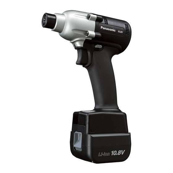
Cordless Impact Driver / Cordless Impact Wrench
PAGE
EYFLA4AR
Model No.
EYFLA5AR
(Cordless Impact
Driver)
EYFLA5QR
Model No.
EYFLA6JR
(Cordless Impact
Wrench)
Europe
© Panasonic Corporation 2016
Unauthorized copying and distribution is a violation
of law.
Order Number PTD1601E08CE
PAGE
Advertisement
Table of Contents

Related Manuals for Panasonic EYFLA4AR


Summary of Contents for Panasonic EYFLA4AR
-
Page 1: Table Of Contents
5 Disassembly and Assembly Instructions ---------------12 6 Measurements and Adjustments---------------------------21 7 Wiring Connection Diagram ---------------------------------24 8 Schematic Diagram ---------------------------------------------25 9 Exploded View and Replacement Parts List -----------26 © Panasonic Corporation 2016 Unauthorized copying and distribution is a violation of law. -
Page 2: Warning
1 Warning Caution: • Pb free solder has a higher melting point that standard solder; Typicall the melting point is 50 - 70F (30 - 40C) higher. Please use a soldering iron with temperature control and adjust it to 750 ± 20F (400 ± 10C). In case of using high temperature solder- ing iron, please be careful not to heat too long. -
Page 3: Troubleshooting Guide
3 Troubleshooting Guide... -
Page 6: Service Fixture And Adjustment
4 Service Fixture and Adjustment 4.1. Check Parts Identify Procedure... - Page 9 4.2. Initializing and Setting NOTE: • This section explains how to revert all tool settings to their default values at the time of shipment from the factory. • The error display will be turned off. INITIALIZING ALL SETTINGS. 1. Set the tool to configuration mode. (See the next procedure ...
- Page 10 CONFIGURING THE TORQUE CLUTCH SETTING. 1. Press the (+) and (-) buttons to select the clutch setting that is appropriate for the work being performed. a. “F” indicates that the torque control function is off. b. You can select from 30 torque clutch settings (1 to 30).
- Page 11 CAUTION: 1. Set the snug point detection level from "L1". Setting the snug point detection level from "L2" may result in cracking or defor- mation of the target material. 2. If the tool stops before the snug point at snug point detection level "L1", set the snug point detection level to "L2". 3.
-
Page 12: Disassembly And Assembly Instructions
5 Disassembly and Assembly Instructions 5.1. Disassembly Instructions Ref. No. 1A Procedure 1A Removal of the Housings. 1. Remove four screws where tightening fixation cover. 2. Pull off the fixing cover assembly. 3. Once removing the fixing cover, the driving shaft assembly may come out. - Page 13 Procedure 1A 1B 1C Ref. No. 1C Removal of housing. 1. Remove nine housing screws. 2. Then open the housing A and B. NOTE: When opening the housings, make sure that the main PCB is on the housing A. If the main PCB sticks in the housing B and pull it out from the hous- ing A, the ribbon cable may be defected.
- Page 14 Procedure 1A 1B 1C 1D 1E Ref. No. 1E Removal of motor assembly. 1. Separate the motor assembly from the driving shaft assembly. 2. Take out the motor rotor assembly from the motor stator. NOTE: Make sure not to damage the magnet by motor rotor. NOTE: Make sure not to scratch FET circuit by motor rotor.
- Page 15 5.2. Reassembly Instructions Ref. No. 2A Procedure 2A Assembly of Motor. 1. Confirm if the metal powder is stuck around the rotor. If so, take out by something like packaging tape. 2. Insert the motor rotor into the stator. Procedure 2A 2B Ref.
- Page 16 Procedure 2A 2B 2C Ref. No. 2C Assembly of Module assembly. 1. Set the DIP switch on the main circuit board with a toothpick. NOTE: Do not use a metal pick. Condition varies with the torque (by model). NOTE: Confirm if "LAR"...
- Page 17 Procedure 2A 2B 2C 2D Ref. No. 2D Assembly of Switch and Motor assembly. 1. Attach the quick connect terminal of the white lead wire from the motor stator with the switch assembly (M+). 2. Apply grease (FLOIL AH-137N-2 / WEWGW2) on the both side and both end of ribbon cable where insert into the connectors.
- Page 18 Procedure 2A 2B 2C 2D 2E Ref. No. 2E Assembly of Switch and Motor assembly. 1. Apply grease (FLOIL AH-137N-2 / WEWGW2) on the connector of transmitter and insert it into the main PCB. 2. Place the transmitter onto the housing. 3.
- Page 19 Procedure 2A 2B 2C 2D 2E 2F Assembly of Driving assembly. Ref. No. 2F 1. Confirm to attach the fixing rubber on Housing B. 2. Insert the motor and driving shaft assembly into the housing. 3.
- Page 20 Procedure 2A 2B 2C 2D 2E 2F Ref. No. 2G Assembly of Driving assembly. 2G 1. Close the housing A and B. 2. Tighten nine housing screws. 3. Apply the grease (DOUBREX / WEY002X8977) all around the anvil. 4.
-
Page 21: Measurements And Adjustments
6 Measurements and Adjustments 6.1. Trial Operation (after checking Troubleshooting Guide.) A. ASSEMBLY Confirm if there is NO gap between Housing A and B by pinching the lead wires. Confirm all screws are tightened firmly. Confirm if there is no deformation on the battery terminal. B. - Page 22 6.2. TRIAL OPERATION (after repairing) Confirm if the repaired unit can communicates with Qualifier. A. MAIN UNIT setting 1. Remove Battery Pack if it is attached. 2. Connect the transmitter with the main unit. 3. Attach Battery Pack. B. QUALIFIER setting 1.
- Page 23 3. Try 3 cycles of impact operation procedure #2. marks will show. D. Confirmation of signal. 1. All procedure from A to C are done, take off the power code of QUALIFIER.Confirmation of signal. 2. Press the switch handle of main unit twice. NOTE: Keep pressing the switch handle about 20 seconds at the second time.
-
Page 24: Wiring Connection Diagram
7 Wiring Connection Diagram... -
Page 25: Schematic Diagram
8 Schematic Diagram... -
Page 26: Exploded View And Replacement Parts List
9 Exploded View and Replacement Parts List 9.1. EXPLODED VIEW for EYFLA4AR... - Page 27 9.2. REPLACEMENT PARTS LIST for EYFLA4AR Safety Ref. No. Part No. Part Name & Description Quantity Remarks WEYFLA4AK329 HOUSING AB SET WEYFLA1AK409 FIXATION COVER ASSEMBLY WEY6507K1166 C-TYPE RING WEY6507L0856 THRUST PLATE WEY6507L0196 BIT HOLDER SPRING WEYFLA1AK379 BIT HOLDER WEYFMA1JL968 SEMS SCREW...
- Page 28 9.3. EXPLODED VIEW for EYFLA5AR...
- Page 29 9.4. REPLACEMENT PARTS LIST for EYFLA5AR Safety Ref. No. Part No. Part Name & Description Quantity Remarks WEYFLA5AK329 HOUSING AB SET WEYFLA1AK409 FIXATION COVER ASSEMBLY WEY6507K1166 C-TYPE RING WEY6507L0856 THRUST PLATE WEY6507L0196 BIT HOLDER SPRING WEYFLA1AK379 BIT HOLDER WEYFMA1JL968 SEMS SCREW (4*25),(4PCS/PK) WEYFLA1AS318 FIXATION COVER...
- Page 30 9.5. EXPLODED VIEW for EYFLA5QR...
- Page 31 9.6. REPLACEMENT PARTS LIST for EYFLA5QR Safety Ref. No. Part No. Part Name & Description Quantity Remarks WEYFLA5QK329 HOUSING AB SET WEYFMA1JL968 SEMS SCREW (4*25),(4PCS/PK) WEYFLA1AS318 FIXATION COVER WEY6505L0866 SLIDER WEYFLA2QL127 ANVIL WEYFLA2NL107 DRIVING SHAFT ASSEMBLY WEY7201L6966 STEEL BALL (7/32),(2PCS/PK) WEYFLA2AL157 HAMMER WEY7205L6957...
- Page 32 9.7. EXPLODED VIEW for EYFLA6JR...
- Page 33 9.8. REPLACEMENT PARTS LIST for EYFLA6JR Safety Ref. No. Part No. Part Name & Description Quantity Remarks WEYFLA6JK329 HOUSING AB SET WEYFMA1JL968 SEMS SCREW (4*25),(4PCS/PK) WEYFLA3JS317 FIXATION COVER WEY6631K0867 SLIDER WEYFLA6JL127 ANVIL WEYFLA3JL107 DRIVING SHAFT ASSEMBLY WEY7201L6966 STEEL BALL (7/32),(2PCS/PK) WEYFLA3JL157 HAMMER WEY7205L6957...