Table of Contents
Advertisement
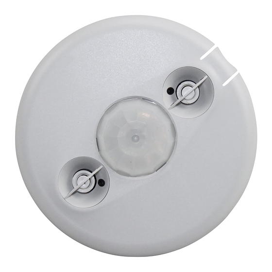
360° Dual Technology • Line Voltage
SPECIFICATIONS
Voltages . . . . . . . . . . . . . . . . . . .120/230/277/347VAC, 50/60Hz
Load Requirements
@120VAC, 50/60Hz . . . . . . . . . . . 0-800W Ballast/Tungsten
@230 or 277VAC, 50/60Hz . . . . . . . . . . . . . 0-1200W Ballast
@347VAC, 50/60Hz . . . . . . . . . . . . . . . . . . . 0-1500W Ballast
Operating Temperature . . . . . . . . . . 32° to 131°F (0° to 55°C)
Terminal Torque Rating . . . 4.428 inch pound-force. (0.5Nm)
Light Level One-Step Adjustment . . . . . . . . . . . . 10FC–300FC
Time Delay Adjustment. . . . . . . . . . . . . . . . . . . 5 to 30 minutes
Walk-Through Mode .3 minutes if no activity after 30 sec.
Test Mode 5 sec. upon intial power-up or DIP switch reset
PIR Coverage (Typical) . . . . . . . . . . . . . . . . . . . . . . . . . 1200 ft2
Sensitivity Adjustment . . . . . . . . . . . . . . . . . . . . . . . . . . . . . .
. . . . . . . . . . . . Automatic or Low (DIP switch setting)
Ultrasonic Coverage (Typical) . . . . . . . . . . . . . . . 800-1200 ft2
Sensitivity Adjustment . . . Minimum to Maximum (trimpot)
Frequency . . . . . . . . . . . . . . . . . . . . . . . . . . . . . . . . . . . 40kHz
DT-355
Occupancy Sensor
with Light Level feature
U.S. Patents: 5,189,393
and Patent Pending
Advertisement
Table of Contents

Related Manuals for wattstopper DT-355


Summary of Contents for wattstopper DT-355
-
Page 1: Specifications
DT-355 360° Dual Technology • Line Voltage Occupancy Sensor with Light Level feature SPECIFICATIONS Voltages ....120/230/277/347VAC, 50/60Hz Load Requirements @120VAC, 50/60Hz ... 0-800W Ballast/Tungsten @230 or 277VAC, 50/60Hz . - Page 2 The DT-355 turns lighting systems on and off based on occupancy and ambient light levels. The light level feature can be used to keep lights from turning on if the ambient light level is sufficient.
- Page 3 It is also recommended to place the sensor 4 to 6 feet away from air supply ducts. Mount the sensor to the ceiling. The DT-355 is designed for a ceiling height of about 8-10 feet. Mounting above or below this range will significantly affect the coverage patterns.
- Page 4 BEFORE INSTALLING SENSORS. #12 to #16 AWG Strip Gauge Cu Wire Only Neutral Load Load Ground Neutral (Optional) Single sensor, single load Neutral Load Load Line Load Line Ground Ground Neutral Neutral (Optional) (Optional) Three-way wiring Visit our website for FAQs: www.wattstopper.com...
- Page 5 LIGHT LEVEL FEATURE The Light Level feature holds lights off upon initial occupancy if adequate ambient light exists. It will not turn the lights off if they are on. The default setting is for maximum, meaning that even the brightest ambient light will not hold the lights off.
- Page 6 MOUNTING THE SENSOR Using a 4-Inch Square Ceiling Junction Box 1. Pull the high voltage wires into 4" Square the J-Box through the conduit Wiremold #V5752 box knockout. CA-1 Adapter 2. Run the wires through the CA-1 adapter then connect the high voltage wires to the appropriate Rear Housing terminals on the sensor.
- Page 7 SENSO R ADJUSTMENT The sensors are factory preset to allow for quick installation in most applications. Verification of proper wiring or coverage, or customizing the sensor’s settings can be done using the following procedures. To make adjustments, open the Front Cover with a small screwdriver. There is a 30 second warm-up period when Ultrasonic...
- Page 8 OCCUPANCY LOGIC Logic Configuration Chart The DT-355 has 6 logic configurations for occupancy triggers, set with DIP switches 1, 2 & 3. Determine the appropriate Occupancy Logic Option using the Trigger matrix, then set Trigger the DIP switches accordingly. Standard...
- Page 9 When enabled, the red PIR and green Ultrasonic Activity LEDs on the sensor will light when the associated sensor detects motion. PIR Sensitivity • Minimum forces a reduced detection range for the PIR. • Max./SmartSet causes the DT-355 to monitor the controlled environment and automatically select the maximum sensitivity that will provide reliable operation without false detection. This setting is constantly updated. Visit our website for FAQs: www.wattstopper.com...
-
Page 10: Troubleshooting
TROUBLESHOOTING WARNING TURN POWER OFF AT THE CIRCUIT BREAKER BEFORE WORKING WITH OR NEAR HIGH VOLTAGE. For any unexpected operation 1. Check DIP switch settings. 2. Make sure the switches are set according to the defined settings in the Logic Configuration Chart. Lights do not turn on with occupancy, and the following condition exists: • Both LEDs do not flash: (DIP switch #7 must be ON to enable the LEDs) 1. - Page 11 To override all sensor functions, set the Ultrasonic Sensitivity trimpot to the fully counterclockwise (Override) position. This bypasses the occupancy and light level control functions of the sensor, but still allows the lights to be manually controlled with a light switch. Visit our website for FAQs: www.wattstopper.com...
-
Page 12: Ordering Information
WattStopper warranties its products to be free of defects in materials and workmanship for a period of five (5) years. There are no obligations or liabilities on the part of WattStopper for consequential damages arising out of or in connection with the use or performance of this product or other indirect damages with respect to loss of property, revenue, or profit, or cost of removal, installation or reinstallation.
Need help?
Do you have a question about the DT-355 and is the answer not in the manual?
Questions and answers
wiring method of wattstopper Dt 355 with override switch