Table of Contents
Advertisement
Quick Links
Advertisement
Table of Contents

Related Manuals for Topcon SP-1P


Summary of Contents for Topcon SP-1P
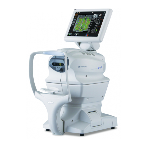
- Page 1 USER MANUAL SPECULAR MICROSCOPE SP-1P...
-
Page 3: Introduction
Thank you for purchasing the TOPCON Specular Microscope SP-1P. INTENDED USE / INDICATIONS FOR USE The Topcon Specular Microscope SP-1P is a non-contact ophthalmic microscope, optical pachymeter, and camera intended for examination of the corneal endothelium and for mea- surement of the thickness of the cornea. - Page 4 3. The contents of this manual are correct to the best of our knowledge. Please inform us of any ambiguous or erroneous descriptions, missing information, etc. 4. Original Instructions This manual was originally written in English. ©2013 TOPCON CORPORATION ALL RIGHTS RESERVED...
-
Page 5: Table Of Contents
CONTENTS INTRODUCTION ........................1 GENERAL SAFETY INFORMATION..................6 HOW TO READ THIS MANUAL ....................8 GENERAL MAINTENANCE INFORMATION ................8 USER MAINTENANCE......................8 CLEANING OF PHOTOGRAPHING WINDOW..............8 DISCLAIMERS.........................8 DISPLAYS AND SYMBOLS FOR SAFE USE .................9 DISPLAYS ........................9 SYMBOLS..........................9 POSITIONS OF WARNING AND CAUTION INDICATIONS ..........10 COMPONENTS COMPONENT NAMES......................11 COMPOSITION OF PARTS WHICH CONTACT THE HUMAN BODY .........11... - Page 6 PRINT-OUT OF PHOTOGRAPHING DATA ................44 DATA OUTPUT........................44 OPERATION OF AFTER USE....................45 OPTIONAL OPERATIONS FREE STYLE COURSE PHOTOGRAPHY................46 PANORAMA PHOTOGRAPHY .....................48 DISPLAYING THE PATIENT ID (PATIENT No.) OR OPERATOR ID ........50 FOR DICOM WORK LIST ....................50 FOR ID INPUT......................50 CELL ANALYSIS IN EDITING MODE ...................51 OUTPUT TO IMAGEnet SYSTEM..................53 INPUT USING USB .......................54 OUTPUT USING LAN......................54...
- Page 7 MANUFACTURER MAINTENANCE ITEMS ..............79 PRINTER PAPER JAM....................80 SUPPLYING THE CHINREST TISSUE................81 MAINTENANCE........................82 CLEANING THE INSTRUMENT...................82 CLEANING THE PHOTOGRAPHING WINDOW GLASS ..........82 CLEANING THE COVER .....................83 CLEANING THE CONTROL PANEL................83 CLEANING THE FOREHEAD REST AND CHIN REST..........83 SP-1P SOFTWARE LICENSE TERMS ..................84...
-
Page 8: General Safety Information
GENERAL SAFETY INFORMATION WARNINGS Ensuring the Safety of Patients and Operators When operating the instrument, do not touch the patient's eye or nose. Handling the cord on this product or cords associated with accessories sold with this product, will expose you to lead, a chemical known to the State of California to cause birth detects or other reproductive harm. - Page 9 CAUTIONS Ensuring the Safety of Patients and Operators To avoid injury when operating the up/down button for the chinrest, be careful not to catch the patient's fingers. The light emitted from this instrument involves potential risk; the longer the irradiation time, the more risk of dam- age to the eye.
-
Page 10: How To Read This Manual
For details, See "CLEANING THE PHOTOGRAPHING WINDOW GLASS" on page 82. DISCLAIMERS • TOPCON is not responsible for damage due to fire, earthquakes, actions or inactions of third persons or other accidents, or damage due to negligence and misuse by the user and any use under unusual conditions. -
Page 11: Displays And Symbols For Safe Use
DISPLAYS AND SYMBOLS FOR SAFE USE In order to encourage the safe use of the instrument and to avoid danger to the operator and others as well as dam- age to properties, warnings are described in the User Manual and marked on the instrument body. We suggest you thoroughly understand the meaning of the following displays/icons and Safety Cautions, as well as read the Manual, and strictly observe the instructions. -
Page 12: Positions Of Warning And Caution Indications
To secure safety, this equipment provides warnings. Correctly use the equipment following these warning instructions. If any of the following marking labels are missing, please contact your dealer or TOPCON at the address stated on the back cover. Label Meaning WARNING To avoid injury caused by electric shock, do not open the cover. -
Page 13: Components
COMPONENTS COMPONENT NAMES Main body Section Photographing head Control panel Power unit Section Printer cover open switch Printer cover External I/O terminal cover Chinrest Section Forehead rest Photographing window Eye height mark Power inlet Chinrest tissue pin Chinrest POWER switch *1: Contacting part (class B) COMPOSITION OF PARTS WHICH CONTACT THE HUMAN BODY Forehead rest : Silicone rubber... -
Page 14: Operation Method Of Control Panel
OPERATION METHOD OF CONTROL PANEL The control panel is designed as a touch panel for performing various operations and settings. It displays images and shows information, including set conditions and photographing results. • The control panel is a touch panel. Do not use any sharp tools; e.g. ball NOTE point pen. -
Page 15: Control Panel Components
CONTROL PANEL COMPONENTS PATIENT SCREEN (DICOM WORK LIST) Patient ID input change button Settings button Operator ID Work list Scroll bar Next button List update button Patient ID input change button.....A patient screen is switched to ID input. Work list ......The work list which is gained by DICOM MWM (Modality Work list Management) server is shown. -
Page 16: Patient Screen (Id Input)
PATIENT SCREEN (ID INPUT) Operator ID Settings button Patient list button Caps Lock button Ten key changeover button Next button Query patient button Patient list button ........Displays the Patient screen (DICOM work list). This button displays when the setting in the Setup screen is ON in "Use DICOM"... -
Page 17: How To Input A Patient Id
HOW TO INPUT A PATIENT ID Tap the on the control panel. Patient ID input change button Patient ID input screen is selected. Tap the input window of patient ID to change the frame color to orange. Input window Enter the Patient ID tapping the Input button Input button If you need to input numeral by ten-key, ten-key input screen appears by tapping the... - Page 18 Tap the to return to the capture screen, check that patient ID is updated. Next button 1081 COMPONENTS...
-
Page 19: Photography Setting Screen
PHOTOGRAPHY SETTING SCREEN Photography point setting button CENTER button Panorama button Multi points button Button to select patient's OD(R) button OU(R/L) button OS(L) button CENTER button ......Centering photography is set. Panorama button......Panorama photography that is to photograph 3 points around the center is set. -
Page 20: Photographing Position (Showing Position Of Ffixation Target) Selecting Screen
PHOTOGRAPHING POSITION (SHOWING POSITION OF FFIXATION TARGET) SELECTING SCREEN When Multi point button is selected in photography point, photographing position selecting screen is shown. Photographing position is determined here. Settings button Selecting position display Return button Next button Selecting position display........The position to be photographed is selected. Settings button ........Displays Setup screen. -
Page 21: Caputer Screen
CAPUTER SCREEN The image to be observed is displayed operating the instrument to tell the state of setting or the result of photography. UNDER PHOTOGRAPHING Display Patient No./Patient ID Operator ID Settings button ID button OD button OS button Photographing position display Photographing position display Please touch pupil Please touch pupil... -
Page 22: Photographing Result Screen
PHOTOGRAPHING RESULT SCREEN Anterior image Corneal endothelium image Analyzing image (basis image) Date of photographing OD button/OS button Photographing point display Photographing position tab Square-shaped distribution graph Print/Output reservation mark Corneal thickness Cell density Area distribution graph Coefficient of variation Frequency of hexagon cells Number of cell analyzed Minimum cell area... -
Page 23: Manual Editing Screen
MANUAL EDITING SCREEN Screen for editing the result of automatic cell analysis. Scroll bar Thumb nail display Excluding button Zoom button Return button Thumb nail display ..........When the image is enlarged the enlarged area is shown. The area is flamed in green. Scroll bar.............Uses to show the hidden list by dragging up and down. -
Page 24: The Checking Screen In The Middle Of Panorama Photography
THE CHECKING SCREEN IN THE MIDDLE OF PANORAMA PHOTOGRAPHY This screen appears when panorama photography is carried out, where 3 images are combined and photographing result of each position is checked. Center Left side Right side OD button/OS button Photographing point display Photographing result Rephotographing button Next button... - Page 25 SETUP SCREEN COMPONENTS...
-
Page 26: List Of Printing Items Screen
LIST OF PRINTING ITEMS SCREEN When more than 2 positions is photographed list of printing items is shown during print/output is car- ried. After print/output is complete, the screen returns to patient screen automatically waiting next patient. Patient ID TOPCON_TAROU If the reliability is low, the character is displayed in yellow. -
Page 27: Printer Output
Maximum cell area TOKO HOSPITAL Average cell area Standard deviation of cell area TOPCON logo mark Input message • As for the patient No., the result of the printing will differ depending on whether the patient ID is inputted or not inputted. - Page 28 Cell density Coefficient of variation cells Frequency of hexagon cells Number of cell analyzed Minimum cell area Maximum cell area Average cell area Standard deviation of cell area Corneal endothelium image TOPCON TOPCON logo mark Input message TOKO HOSPITAL COMPONENTS...
-
Page 29: Standard Accessories
STANDARD ACCESSORIES The following are standard accessories. Make sure that all these items are included (quantity). User manual, Instruction manual, Power cable (1) Unpacking and Assembling (1 each) Dust cover (1) Printer paper (2) Monitor cleaner (1) Chinrest tissue (1) Chinrest tissue pin (2) Stylus pen (1) COMPONENTS... -
Page 30: Preparations
PREPARATIONS INSTALLATION • When moving the instrument, two people should lift from the bot- tom of the device. One person lifting the device may cause harm to his back or injury by falling parts. Also, holding areas other than the bottom and holding the External I/O terminal cover may cause injury, as well as damage to the instrument. -
Page 31: Connecting External I/O Terminals
Connect the power cable to the Power inlet. Insert the power cable plug into the commercial power (the 3-pin AC grounding receptacle.) CONNECTING EXTERNAL I/O TERMINALS To avoid electric shock, do not touch the external connection CAUTION terminal and the patient at the same time. When connecting this product with a commercial personal computer, use NOTE one conforming to IEC60950-1. -
Page 32: Imagenet
• Do not insert or remove the LAN cable while the power of the instrument is • Sometimes the connection is not done properly because of the character- istics of the hardware. Use the LAN cable specified by TOPCON. DATA INPUT This product can be connected to a bar-code reader and other external devices via USB. -
Page 33: Printer Paper Setting
PRINTER PAPER SETTING • To avoid failure or potential injury, do not open the printer cover while the printer is in operation. • To avoid potential injury in case of malfunction, including a paper CAUTION jam, be sure to shut off the power before attempting to repair it. •... - Page 34 Insert the printer paper in the direction shown below and pull out the paper end to your side by 7 to 8cm. Roll direction Bring the paper into the center, then close the printer cover. • If the printer cover is closed when the power is ON, the paper cut opera- tion is carried out automatically.
-
Page 35: Recovery From Power Save Status
RECOVERY FROM POWER SAVE STATUS This instrument adopts the power save system for saving electric power. When the machine is not operated for a set time, the control panel becomes a screensaver. Tap the control panel or operate the control lever. In a few seconds, the measurement screen is displayed and photography is enabled. -
Page 36: Basic Operations
BASIC OPERATIONS OPERATION FLOW CHART Two different operation flows are available sequence course and free style course. Before ship- ment, default setting is sequence course. • Sequence course ....Setting Patient ID, photography point and patient's eye is required before photographing. (In current chapter) •... -
Page 37: Preparation Before Photographing (Sequence Course)
PREPARATION BEFORE PHOTOGRAPHING (SEQUENCE COURSE) • Do not put the patient's chin on the chinrest until the power is on. • If room temperature becomes low at 10°C or less in the winter, after turned NOTE the power switch on, warming up is necessary before use. Image quality may be influenced for low temperature. -
Page 38: Select Photography Point And Patient's Eye
SELECT PHOTOGRAPHY POINT AND PATIENT'S EYE Tap the photography point setting button. Photography point setting button Button to select patient's eye CENTER button ..Centering photography is carried out. Panorama button..Panorama photography that is to photograph 3 points around the center is set. -
Page 39: Preparation Of Patient
PREPARATION OF PATIENT • To avoid electric shock, do not touch the external connection ter- minal and the patient at the same time. • To avoid injury, do not insert fingers under the chinrest. To avoid injury when moving the chinrest down, be careful not to CAUTION catch the patient's finger. - Page 40 Press the to adjust the chinrest height until the eye height mark of the chin- UP/DOWN button rest reaches the same height as the patient's eye. At this moment, confirm that the height mark of the photographing window is at the height of the patient's visual line. Up/Down button for chinrest Eye height mark BASIC OPERATIONS...
-
Page 41: Photography And Analysis Result Display
PHOTOGRAPHY AND ANALYSIS RESULT DISPLAY • Photographing may not be possible, in case the eyelid and the eyelashes cover the pupil. If this occurs, the operator should tell the patient to open their eyes as wide as possible, or lift the eyelid to allow for measurement. •... - Page 42 • When the photographing head has reached the limit of movement (verti- cal/lateral directions), a yellow-colored limit mark appears on the control panel’s top, showing it is the movement limit in that direction. Tap the dis- play, move the photographing head to the position where aligning is possi- ble.
- Page 43 Results of Photography and analysis. Anterior image Corneal endothelium image Analyzing image (basis image) Date of photographing OD button/OS button Photographing position display Photographing position tab Square-shaped distribution graph Print/Output reservation mark Corneal thickness Cell density Area distribution graph Coefficient of variation Frequency of hexagon cells Number of cell analyzed Minimum cell area...
-
Page 44: In Manual Alignment
Under "Panorama photography" is set, the procedure is follows; "photographing" - "check the photographing result" - "photographing" - "check the photographing result", then repeat same procedure. Photographing is performed at three points as center, ear side, and nose side. Under "Multi points photography" is set, the procedure is "photographing" and "check the photo- graphing result", and repeat same procedure according to selected points. - Page 45 During vertical/lateral directions movement, the movement mode is changed to back /forth by tapping (at one second) the center of screen. NOTE Under Back/forth movement mode, it is possible to move like the arrow of the screen. BASIC OPERATIONS...
-
Page 46: Print-Out Of Photographing Data
PRINT-OUT OF PHOTOGRAPHING DATA • To avoid a paper jam in the printer, do not feed the paper if it is partly cut or wrinkled. • To avoid discoloring of the printer paper (particularly the recording area) during storage, use a polypropylene bag and not one containing plasti- NOTE cizer (PVC, etc.). -
Page 47: Operation Of After Use
OPERATION OF AFTER USE Tap the on the control panel. End button The message of "Turn off the unit?" is displayed. Tap the "YES". Return the chinrest and photographing head to the last position. The message of "Please don't turn the main switch off until the unit stops." is displayed on the control panel. -
Page 48: Optional Operations
OPTIONAL OPERATIONS FREE STYLE COURSE PHOTOGRAPHY In the free style course, it is possible to capture an eye as soon as the power turns on; selecting the patient's ID, photography point or patient's eye is not required. • To change to free style course form the sequence course the setup screen is used. - Page 49 Start Preparation of patient (Refer to P.37 "PREPARATION OF PATIENT") Carry out Photographing. (Refer to P.39 "ALIGNMENT AND PHOTOGRAPHY") Results of Photography and analysis are displayed. If photographing of the required position is complete, select the result for printing position. Photographing position tab Print/Output reservation mark...
-
Page 50: Panorama Photography
PANORAMA PHOTOGRAPHY Photograph 3 points-center, ear side and nose side. Those images are combined automatically and observation of large area can be performed. • In the case of sequence course, preparation and photography are carried out as the follow- ing procedure. •... - Page 51 Check the result of photography. If photography is required again, tap the Rephotographing button. Left side Center Right side OD button/OS button Photographing point display Result of photography Rephotographing button Next button Tap the to photograph next position. Next button The capture screen is shown.
-
Page 52: Displaying The Patient Id (Patient No.) Or Operator Id
Check the analyzing result and if required tap the to print/output the Print/Output button result. Analyzing screen of combined image Print/Output button The List of printing items screen is displayed, then tap the print/output button. The analyzing result is printed. Print/Output button The message of "Are you sure to start next measurement? Please select whether to input new patient ID or not."... -
Page 53: Cell Analysis In Editing Mode
CELL ANALYSIS IN EDITING MODE If the detailed mode setting is ON, editing button is shown. Use of a stylus pen is recommended to edit. Make sure that Photographing result screen is displayed. Various data Icon Tap the manual editing button . - Page 54 Tap the , then the message of "Are you sure to apply change?" is displayed. Analyze button Analyze button If tapping "OK", the analyzing screen where the change was applied is displayed. If tapping "Cancel", the analyzing screen where the change was discarded is displayed. OPTIONAL OPERATIONS...
-
Page 55: Output To Imagenet System
OUTPUT TO IMAGEnet SYSTEM • Set LAN output to ON. Check the connection of IMAGEnet system. For connection, refer to "CONNECTING EXTERNAL I/O TERMINALS" on page 29. Photographing is performed at all position. Tap the on the screen to display the List of printing items Print/Output button screen. -
Page 56: Input Using Usb
INPUT USING USB This instrument can input ID numbers from a bar code reader, etc. via the USB. Check the connection of USB IN. For connection, refer to "CONNECTING EXTERNAL I/O TERMINALS" on page 29. Input ID numbers from the external device. The inputted ID numbers are displayed on the screen. -
Page 57: Setting Functions On Setup Screen
SETTING FUNCTIONS ON SETUP SCREEN OPERATING THE SETUP SCREEN Various functions can be set on the SETUP screen. PREPARATONS FOR SETTING Make sure that the power cable is connected. For connection, refer to "CONNECTING POWER CABLE" on page 28. Turn ON the switch. -
Page 58: Outline Of Setup Screen Operations
OUTLINE OF SETUP SCREEN OPERATIONS and select the subject of setting. INDEX Initial Capture mode Settings Internal Free style start Printer screen External Buzzer Printer Network Stand by mode Settings Operator Patient IDreset Settings Exit Operate the button or button, as necessary, and display the page NEXT PAGE BACK PAGE to confirm/change. - Page 59 PULL-DOWN MENU: Tap the options button to show a pull-down menu. Select a figure and value etc. to be changed in menu items. Initial Show device ID Settings number Internal Device ID number Printer External Pupil distance 64(mm) Printer Pull-down menu Network Auto power save Settings...
-
Page 60: Returning To The Measurement Screen
NOTE The set value is updated when an options button is tapped. RETURNING TO THE MEASUREMENT SCREEN Tap the button. Exit Operator Patient IDreset Settings Exit The capture screen is displayed. SETTING FUNCTIONS ON SETUP SCREEN... -
Page 61: List Of Setup Items
LIST OF SETUP ITEMS Setup items are categorized into 6 large indexes. "Initial Settings" ......items related to the initial status after power on "Internal Printer" ......items related to output from the internal print "External Printer" .......items related to output from the external print "Network Settings".....items related to output using the LAN "Operator Settings"....items related to Operator ID INITIAL SETTINGS... -
Page 62: Internal Printer
Endothelium image is not printed. Message is printed. Print message Message is not printed. -None- Message String of up to 72 characters. -None- No message TOPCON logo is printed. TOPCON logo TOPCON logo is not printed. SETTING FUNCTIONS ON SETUP SCREEN... -
Page 63: External Printer
AUTO Assign IP address automatically. -None- IP address IP address of PC to output data. -None- IP address -None- Subnet mask Subnet mask address of SP-1P. -None- IP address -None- Default gateway Default gateway address of SP-1P. -None- IP address... - Page 64 Description Options Details Initial value Character string Storage server Host name or IP address of the work list server. -None- Floating keyboard 0-65535 Storage server port Access port number of the work list server. Set by ten-key display. Character string Storage server AE title AE name of the storage server.
-
Page 65: Operator Settings
OPERATOR SETTINGS OPERATOR contains settings related to Operator ID. Description Options Details Initial value Operator ID will not be displayed on the control panel and output. Use of operator ID Operator ID will be displayed on the control panel and output. ASCIIZ string up to Prefix of Ope. -
Page 66: Troubleshooting
TROUBLESHOOTING TROUBLE-SHOOTING OPERATIONS MESSAGE LIST "ERROR" Displayed when the photographing is an error. "Close printer cover" The printer cover is open. Close the cover until it clicks. "Paper end" Printer paper is used up. Supply printer paper. "Fatal Error!" Displayed when the printer unit does not operate normally, such as the cutter does not work. - Page 67 "Turn off the unit?" Displayed to confirm whether to move the chinrest and measuring head to their last positions. "Please wait until packing mode Indicates that the packing operation is in process. Wait until it is completed. is finished..." "Packing mode is finished. Indicates that the packing operation is completed.
-
Page 68: Trouble-Shooting Operations
If a problem is suspected, use the following check list. If following instructions does not improve the condition, or if your problem is not included in the list, con- tact your dealer or TOPCON at the address on the back cover. CHECK LIST... -
Page 69: Specifications And Performance
SPECIFICATIONS AND PERFORMANCE SPECIFICATIONS AND PERFORMANCE Item Specifications Corneal endothelium photography Photography magnification 254x (on the control panel: within ±8%) Photography range 0.25x0.55mm (within ±8%) Resolving power More than 125 line/mm Fixation target Central and peripheral Corneal thickness measurement Measurement range 0.400-0.750mm Display unit: 0.001mm step display Allowance: Less than 0.600mm within ±0.010mm... -
Page 70: General Information On Usage And Maintenance
• To keep the eye open. • To understand and follow instructions when undergoing an examination. INTENDED USER PROFILE Since the Specular Microscope SP-1P is a medical device, the operation should be supervised by a physician. ENVIRONMENTAL CONDITIONS OF USE Temperature: 10°C to 40°C... -
Page 71: Environmental Conditions For Packaging In Transportation
ENVIRONMENTAL CONDITIONS FOR PACKAGING IN TRANSPORTATION (Product in its normal transport and storage container as provided by manufacturer) Temperature : -40°C to 70°C Humidity : 10% to 95% ELECTRIC RATING Source voltage: 100-240V AC, 50-60Hz Power input: 70-120VA SAFETY DESIGNATIONS PER IEC 60601-1 STANDARD •... -
Page 72: Operation Principle
OPERATION PRINCIPLE Photography of the corneal endothelium: Slit light is projected from oblique direction to a patient's eye, and corneal endothelial cells are photo- graphed with the CCD camera optically installed in a diagonal. Image processing of the photographed corneal endothelial cells is carried out, the boundary of a cell is detected, and the area (Cell density (CD), Minimum cell area (MIN), Maximum cell area (MAX), Average cell area (AVG), Standard devia- tion of cell area (SD), Coefficient of variation (CV) and cell area histogram) and the form (Frequency of hexagon cells (HEX) and form histogram (angle of cell)) are computed. -
Page 73: Checkpoints For Maintenance
CHECKPOINTS FOR MAINTENANCE 1. Regularly maintain and check the equipment and parts. 2. When resuming the use after a long period of storage, verify that the instrument operates cor- rectly and safely. 3. To ensure the correct reading, do not mar the photographing window with finger prints, dust, etc. 4. -
Page 74: Electromagnetic Compatibility
Guidance and manufacturer's declaration - electromagnetic emissions The SP-1P is intended for use in the electromagnetic environment specified below. The customer or the user of the SP-1P should assure that it is used in such an environment. Emissions test Compliance Electromagnetic environment - guidance The SP-1P uses RF energy only for its internal function. - Page 75 Guidance and manufacturer's declaration - electromagnetic immunity The SP-1P is intended for use in the electromagnetic environment specified below. The customer or the user of the SP-1P should assure that it is used in such an environment. IEC 60601 Compliance...
- Page 76 To assess the electromagnetic environment due to fixed RF transmitters, an electromagnetic site survey should be considered. If the measured field strength in the location in which the SP-1P is used exceeds the applicable RF compliance level above, the SP-1P should be observed to verify normal operation.
-
Page 77: Requirements For The External Device
RF communications equipment and the SP-1P The SP-1P is intended for use in an electromagnetic environment in which radiated RF disturbances are con- trolled. The customer or the user of the SP-1P can help prevent electromagnetic interference by maintaining a minimum distance between portable and mobile RF communications equipment (transmitters) and the SP-1P as recommended below, according to the maximum output power of the communications equipment. -
Page 78: Patient's Environment
PATIENT'S ENVIRONMENT When the patient or inspector comes into contact with the devices (including the connecting devices) or when the patient or inspector is in contact with the person that touches the devices (including the connecting devices), the patient's environment is shown below. In the patient's environment, use devices conforming to IEC60601-1. -
Page 79: Reference
REFERENCE OPTIONAL ACCESSORIES • Adjustable instrument table AIT-16 The table height can be adjusted to facilitate measurement. Specifications • Dimensions....525(W)x490(D)mm • Table height ....660~880mm • Table size .....490x500mm • Weight ......approx. 23kg • Power consumption..150VA (100-120V, 220-240V) SHAPE OF PLUG Country Voltage/frequency Shape of plug... -
Page 80: Maintenance
NOTE measuring head to their initial positions. ORDERING CONSUMABLE ITEMS • When ordering consumable items, tell the product name, product code and quantity to your dealer or TOPCON at the address of back cover. Product name Product code Product name... -
Page 81: User Maintenance Item
USER MAINTENANCE ITEM Item Inspection time Contents • The instrument works properly. Inspection Before using • The photographing window must be free of stain or flaw. • Photographing window Cleaning When the part is stained • External cover, control panel, etc. Replacement As required •... -
Page 82: Printer Paper Jam
PRINTER PAPER JAM • To avoid failure or potential injury, do not open the printer cover while the printer is in operation. • To avoid potential injury in case of malfunction, including a paper jam, be sure to shut off the power before attempting to repair it. •... -
Page 83: Supplying The Chinrest Tissue
SUPPLYING THE CHINREST TISSUE • When the chinrest tissue has run out, pull off chinrest tissue pins and place new tissue. Chinrest tissue pins Chinrest tissue MAINTENANCE... -
Page 84: Maintenance
MAINTENANCE To avoid electric shocks, make sure the power is off and the power CAUTION cable is unplugged before maintenance. • To avoid damage to the instrument or electric shock, turn the power switch OFF and unplug the power cord before maintenance. •... -
Page 85: Cleaning The Cover
• Replace new applicator and repeat cleaning. It is complete when stains can be wiped off finely. If the stains are still hard to remove, contact your dealer or the TOPCON sales department. CLEANING THE COVER Do not clean plastic parts with solvents. Benzine, thinner, ether and gasoline NOTE may cause discoloring and decomposition. -
Page 86: Sp-1P Software License Terms
Digia Plc and its licenser posses the copyright and the intellectual property right of the "Qt" soft- ware installed in SP-1P. TOPCON CORPORATION grants to you the right to use this SP-1P Software under the terms and condi- tions outlined below. - Page 87 LICENSE TERMS. 7. LIMITED WARRANTY 7.1 In the event that a hidden material defect is found by USER, USER shall notify TOPCON in writing of such defect directly or through its subsidiary, affiliate, distributor or agent within ninety (90) days after USER has received the SOFTWARE.
- Page 88 THE ENTIRE RISK ARISING OUT OF, RESULTING FROM OR IN CONNECTION WITH THE USE OR PERFORMANCE OF THE SOFTWARE REMAINS WITH THE USER. IN NO EVENT SHALL TOPCON OR ITS SUBSIDIARIES, AFFILIATES, DISTRIBUTORS OR AGENTS BE LIABLE FOR ANY CONSEQUENTIAL, INCIDENTAL, DIRECT, INDIRECT, SPECIAL, PUNITIVE, OR OTHER...
- Page 89 TERMS shall be governed by and under the laws of Japan. 11. ENTIRE AGREEMENT These LICENSE TERMS constitute the entire agreement between USER and TOPCON with respect to the subject matter hereof, and shall supersede and cancel any and all prior written or oral agreements, undertakings, negotiations, communications, commitments, representations, publications and adver- tisement, etc.
- Page 91 Period of use: Please inform us of the date of purchase. ● Defective condition: Please provide us with as much detail as possible. SPECULAR MICROSCOPE SP-1P USER MANUAL 2013 version (2013.08-100LW0) Date of issue: August 1st, 2013 Published by TOPCON CORPORATION 75-1 Hasunuma-cho, Itabashi-ku, Tokyo, 174-8580 Japan.
- Page 92 SPECULAR MICROSCOPE SP-1P 41904 97030 Printed in Japan 1308-100LW0...
Need help?
Do you have a question about the SP-1P and is the answer not in the manual?
Questions and answers