Table of Contents
Advertisement
Specification
nAMPLIFIER SECTION
RMS output power: Dolby Digital Mode
T.H.D. 10% (Each channel driven)
1 kHz front CH
1 kHz surround CH
1 kHz center CH
Total RMS output power
RMS output power: STEREO Mode
T.H.D. 10%
1 kHz front CH
Total harmonic distortion
Half power at 1 kHz (Front CH)
Input sensitivity
TV, DVR/DVD-P, GAME/AUX
MUSIC PORT
S/N at rated power (6 Ω)
TV, DVR/DVD-P, GAME/AUX
MUSIC PORT
Input impedance
TV, DVR/DVD-P, GAME/AUX, MUSIC PORT
Tone controls
150 W per channel (6 Ω)
80 W per channel (4 Ω)
80 W per channel (4 Ω)
540 W
150 W per channel (6 Ω)
0.5% (6 Ω)
450 mV, IHF'66
250 mV, IHF'66
80 dB (85 dB, IHF'66)
70 dB (85 dB, IHF'66)
47 kΩ
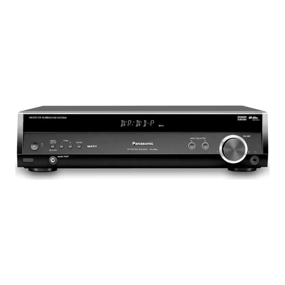
AV Control Receiver
SA-HR45E
SA-HR45EG
Colour
(S).......................Silver Type
(K).......................Black Type
BASS
TREBLE
Load impedance
Front (L/R)
Surround (L/R)
Center
Digital input
OPTICAL
COAXIAL
nFM TUNER SECTION
Frequency range
Sensitivity
S/N 30 dB
S/N 26 dB
S/N 20 dB
IHF usable sensitivity
IHF 46 dB stereo quieting sensitivity
Total Harmonic distortion
MONO
STEREO
S/N
MONO
STEREO
Frequency response
Image rejection at 98 MHz
IF rejection at 98 MHz
ORDER NO. MD0707047CE
50 Hz, +10 to -10 dB
20 kHz, +10 to -10 dB
6 Ω to 8 Ω
4 Ω to 8 Ω
4 Ω to 8 Ω
2
1
87.50 MHz to 108.00 MHz
1.9 µV/75 Ω
1.8 µV/75 Ω
1.6 µV/75 Ω
(IHF'58) 2.2 µV/75 Ω
22 µV/75 Ω
0.2%
0.3%
60 dB (71 dB, IHF)
58 dB (65 dB, IHF)
20 Hz to 15 kHz, +1 dB, -2 dB
40 dB
70 dB
Advertisement
Table of Contents

Related Manuals for Panasonic SA-HR45E


Summary of Contents for Panasonic SA-HR45E
- Page 1 ORDER NO. MD0707047CE AV Control Receiver SA-HR45E SA-HR45EG Colour (S).......Silver Type (K).......Black Type Specification nAMPLIFIER SECTION BASS 50 Hz, +10 to -10 dB RMS output power: Dolby Digital Mode TREBLE 20 kHz, +10 to -10 dB T.H.D. 10% (Each channel driven) Load impedance 6 Ω...
-
Page 2: Table Of Contents
SA-HR45E / SA-HR45EG Stereo separation (1 kHz) 40 dB 430 mm x 105 mm x 385 mm 75 Ω (unbalanced) Antenna terminal Mass 3.8 kg nAM TUNER SECTION Power consumption in standby mode: Frequency range Notes: 522 kHz to 1611 kHz (9 kHz steps) 1. -
Page 3: Safety Precautions
SA-HR45E / SA-HR45EG 1 Safety Precautions 1.1. General Guidelines 1. When servicing, observe the original lead dress. If a short circuit is found, replace all parts which have been overheated or damaged by the short circuit. 2. After servicing, see to it that all the protective devices such as insulation barriers, insulation papers shields are properly installed. -
Page 4: Prevention Of Electro Static Discharge (Esd) To Electrostatically Sensitive (Es) Devices
SA-HR45E / SA-HR45EG 2. Determine the cause of the problem and correct it. 3. Press the STANDBY /ON button once again, supply the power. Note: When the protection circuitry functions, the unit will not operate unless the STANDBY /ON button is first switched STANDBY and then ON again. -
Page 5: About Lead Free Solder (Pbf)
SA-HR45E / SA-HR45EG to the chassis or circuit assembly into which the device will be installed. Caution Be sure no power is applied to the chassis or circuit, and observe all other safety precautions. 8. Minimize body motions when handling unpackaged replacement ES devices. (Otherwise harmless motion such as the brushing together of your clothes fabric or the lifting of your foot from a carpeted floor can generate static electricity (ESD) sufficient to damage an ES device). -
Page 6: Accessories
SA-HR45E / SA-HR45EG 4 Accessories Note: Refer to Replacement Part list (Section 18) for the part number. -
Page 7: Operation Procedures
SA-HR45E / SA-HR45EG 5 Operation Procedures 5.1. Remote Control Operation... - Page 8 SA-HR45E / SA-HR45EG 5.2. Main Unit Operation...
- Page 9 SA-HR45E / SA-HR45EG...
- Page 10 SA-HR45E / SA-HR45EG 5.3. Basic operations 5.4. Main Unit Connection (SA-HR45) 5.4.1. Speaker setup...
- Page 11 SA-HR45E / SA-HR45EG 5.4.2. Home theater connections...
-
Page 12: Self Diagnosis And Special Mode Setting
SA-HR45E / SA-HR45EG 6 Self Diagnosis and Special Mode Setting This unit is equipped with function for checking and inspecting namely: Self-Diagnostic and Test Mode. 6.1. Service Mode Summary Table The service mode can be activated by pressing various button combination on the main unit and remote control unit. Below is the... - Page 13 SA-HR45E / SA-HR45EG 6.2. Doctor & Service Mode (Special Mode setting)
- Page 14 SA-HR45E / SA-HR45EG 6.2.1. Inspection & Checking Items After entering into doctor mode, the main unit can be used for checking of various items using the remote control. 6.3. Error Code Table Self- Diagnosis Function provides information on any problems occuring for the units and its respective parts by displaying error...
-
Page 15: Assembling And Disassembling
SA-HR45E / SA-HR45EG 7 Assembling and Disassembling 7.1. Caution “Attention Servicer” Some chassis components may have sharp edges. Be careful when disassembling and servicing. 1. This section describes procedures for checking the operation of the major printed circuit boards and replacing the main components. - Page 16 SA-HR45E / SA-HR45EG 7.2. Disassembly Flow Chart The following chart is the procedure for disassembling the casing and inside parts for internal inspection when carrying out the servicing. To assemble the unit, reverse the steps shown in the chart as below.
- Page 17 SA-HR45E / SA-HR45EG 7.3. Main Components and P.C.B Locations.
- Page 18 SA-HR45E / SA-HR45EG 7.4. Disassembly of Top Cabinet 7.5. Disassembly of Rear Panel • Follow the (Step 1) - (Step 4) of item 7.4. - Disassembly of Step 1: Remove 1 screw at each side of the top cabinet. Top Cabinet.
- Page 19 SA-HR45E / SA-HR45EG 7.6. Disassembly of Front Panel • Follow the (Step 1) - (Step 4) of item 7.4. - Disassembly of Top Cabinet. Step 1: Detach the wires on connections (CN400, CN402 & CN401) on Main P.C.B. and (CN801) at Power P.C.B..
- Page 20 SA-HR45E / SA-HR45EG Step 3: Remove 3 screws as picture shown. Step 4: Release the 2 catches and lift up the front Plate. • Disassembly of Panel P.C.B. and Music Port P.C.B. Step 5: Remove 9 screws at Panel P.C.B..
- Page 21 SA-HR45E / SA-HR45EG 7.9. Disassembly of DSP P.C.B. • Follow the (Step 1) - (Step 4) of item 7.4. - Disassembly of Top Cabinet. Step 1: Remove 3 screws at rear panel. Step 5: Lift up and remove DSP P.C.B as shown in picture.
- Page 22 SA-HR45E / SA-HR45EG 7.11. Disassembly of Power P.C.B. • Follow the (Step 1) - (Step 4) of item 7.4. - Disassembly of Top Cabinet. • Follow the (Step 1) - (Step 5) of item 7.10. - Disassembly of AC Inlet P.C.B..
- Page 23 SA-HR45E / SA-HR45EG Caution: Handle the heat sink power unit with caution due to its high temperature after prolonged use. Touching it, may lead to injuries. Step 8: Remove 3 screws (from IC800, D855 and D856). Caution: Handle the heat sink power unit with caution due to its high temperature after prolonged use.
- Page 24 SA-HR45E / SA-HR45EG • Replacement of the Power Amp IC Step 6: Remove 4 screws at the IC Clamp. Caution: Handle the heat sink power unit with caution due to its high temperature after prolonged use. Touching it, may lead to injuries.
-
Page 25: Service Positions
SA-HR45E / SA-HR45EG 8 Service Positions Note: Checking of all Major P.C.B. (Main P.C.B., DSP P.C.B., AC Inlet P.C.B., Digital Amp P.C.B., Power P.C.B., Panel P.C.B., Music Port P.C.B. & Volume P.C.B.) can be carried out using below procedures. For description of the disassembling procedure, see Section 7. - Page 26 SA-HR45E / SA-HR45EG 8.2. Checking & Repairing DSP P.C.B. (Side B)
- Page 27 SA-HR45E / SA-HR45EG 8.3. Checking & Repairing Panel P.C.B., Music Port P.C.B. and Volume P.C.B.
- Page 28 SA-HR45E / SA-HR45EG 8.4. Checking & Repairing Main P.C.B., Power P.C.B. & Digital Amp P.C.B.
-
Page 29: Voltage Measurement And Waveform Chart
SA-HR45E / SA-HR45EG 9 Voltage Measurement and Waveform Chart Notes: • Indicated voltage values are the standard values for the unit measured by the DC electronic circuit tester (higher-impedance) with the chassis taken as standard. Therefore, there may exist some errors in the voltage values, depending on the internal impedance of the DC circuit tester. - Page 30 SA-HR45E / SA-HR45EG 9.1.2. Main P.C.B.
- Page 31 SA-HR45E / SA-HR45EG 9.1.3. Power P.C.B. 9.1.4. Panel P.C.B.
- Page 32 SA-HR45E / SA-HR45EG 9.1.5. Digital Amp P.C.B.
- Page 33 SA-HR45E / SA-HR45EG 9.2. Waveform Chart CN105 PIN 3 CN105 PIN 10 CN400 PIN 5 CN400 PIN 8 CD PLAY CD PLAY CD PLAY CD PLAY 5.52Vp-p (5usec.div) 5.12Vp-p (500usec.div) 1.48Vp-p (1usec.div) 864mVp-p (500nsec.div) CN402 PIN 5 CN402 PIN 6...
- Page 34 SA-HR45E / SA-HR45EG IC301 PIN 33 IC301 PIN 69 IC301 PIN 76 IC1001 PIN 3 CD PLAY CD PLAY CD PLAY CD PLAY 5.28Vp-p (10usec.div) 5.04Vp-p (10msec.div) 5.12Vp-p (500usec.div) 3.48Vp-p (5usec.div) IC1001 PIN 7 IC1001 PIN 22 IC1001 PIN 25...
- Page 35 SA-HR45E / SA-HR45EG IC1101 PIN 1 IC1101 PIN 2 IC1101 PIN 3 IC1101 PIN 7 CD PLAY CD PLAY CD PLAY CD PLAY 3.48Vp-p (10usec.div) 3.32Vp-p (250nsec.div) 3.16Vp-p (25usec.div) 6.16Vp-p (10usec.div) IC1101 PIN 8 IC1101 PIN 9 IC1101 PIN 10...
- Page 36 SA-HR45E / SA-HR45EG...
-
Page 37: Wiring Connection Diagrams
SA-HR45E / SA-HR45EG 10 Wiring Connection Diagrams CN400 CP101 (TO TUNER PACK) 1....10 5..1 JW801 15..8 7..1... - Page 38 SA-HR45E / SA-HR45EG...
-
Page 39: Block Diagram
SA-HR45E / SA-HR45EG 11 Block Diagram IC1201 CP101 C0ABBB000297 TUNER PACK OP-AMP IC152 C0CBAHG00011 36(35) 3(5) VOLTAGE AOUTA(B)1+ 1(7) 37(34) 2(6) REGULATOR CDOUT AOUTA(B)1- IC1202 FM DETECT C0ABBB000297 TUNER_CLK OP-AMP TUNER_ST STEREO 32(31) 3(5) AOUTA(B)2+ TUNER_SD 1(7) JK1301 TUNED DIGITAL IN... - Page 40 SA-HR45E / SA-HR45EG IC150 IC151 C1BB00001134 C0ABBB000297 JK504 AUDIO SIGNAL IC203 IC552 OP-AMP SURROUND (R) PROCESSOR C0ABBB000297 C1AA00000755 IC850 OP-AMP POWER AMP C0DAEMZ00001 JK504 POWER SUPPLY 40(41) Q880 Q881 3(5) SLOUT(R) SURROUND (L) 1(7) 2(22) SWOUT 2(6) DETECT DETECT COUT...
-
Page 41: Notes Of Schematic Diagram
SA-HR45E / SA-HR45EG 12 Notes of Schematic Diagram • This schematic diagram may be modified at any time with • Voltage and Signal lines: the development of new technology.. : +B signal line Notes: : -B signal line S401 POWER SWITCH ( S402 <... - Page 42 SA-HR45E / SA-HR45EG...
-
Page 43: Schematic Diagram
SA-HR45E / SA-HR45EG 13 Schematic Diagram 13.1. (A) DSP Circuit SCHEMATIC DIAGRAM - 1 DSP CIRCUIT : +B SIGNAL LINE : MAIN SIGNAL LINE C1005 C1006 C1020 10V0.1 50V1 R1015 R1017 R1021 4.7K 4.7K IC1004 C0JBAZ002160 C1015 LOGIC 100P C1001... - Page 44 SA-HR45E / SA-HR45EG SCHEMATIC DIAGRAM - 2 DSP CIRCUIT : +B SIGNAL LINE : -B SIGNAL LINE : MAIN SIGNAL LINE R1201 R1231 C1231 5.6K 5.6K 16V10 C1201 R1232 R1237 R1207 R1222 1800P 2.7K 1.5K -7.5V C1216 C1202 R1213 1200P 1.5K...
- Page 45 SA-HR45E / SA-HR45EG 13.2. (B) Main Circuit SCHEMATIC DIAGRAM - 3 MAIN CIRCUIT : +B SIGNAL LINE : -B SIGNAL LINE : MAIN SIGNAL LINE : FM / AM SIGNAL LINE : AUX / MUSIC PORT SIGNAL LINE : TV AUDIO SIGNAL LINE R110 -7.5V...
- Page 46 SA-HR45E / SA-HR45EG SCHEMATIC DIAGRAM - 4 MAIN CIRCUIT : +B SIGNAL LINE : -B SIGNAL LINE : MAIN SIGNAL LINE : MUSIC PORT SIGNAL LINE Q206 B1ABDC000010 HEADPHONE MUTING R3077 R209 C1006 0.18 CONTROL SNE3 R213 C251 R3070 R236 R235 3.9K...
- Page 47 SA-HR45E / SA-HR45EG SCHEMATIC DIAGRAM - 5 MAIN CIRCUIT : +B SIGNAL LINE : -B SIGNAL LINE : MAIN SIGNAL LINE : MUSIC PORT SIGNAL LINE CN401 MUSIC_SW MUSIC_SW MUSIC_R MUSIC_R W550 MUSIC_GND R280 C304 1000P -7.5V W549 MUSIC_L MUSIC_L...
- Page 48 35V470 J0JKB0000020 -29V -30V POWER L507 ETQA17B150 CIRCUIT C5509 C5008 POWER_GND 35V470 (JW850) IN POWER_GND SCHEMATIC LB500 DIAGRAM-9 J0JKB0000020 +30V +29V +30V C540 C5005 C5508 C5007 35V470 35V470 Q5005 CN850 B1BACG000023 C5004 R5007 REGULATOR D5006 MAZ80620ML SA-HR45E/EG DIGITAL AMP CIRCUIT...
- Page 49 C580 JK504 LB505 35V470 0.68 C582 J0JKB0000020 -29V R535 C583 C581 0.68 SIGNAL R527 R5512 R5513 L503 R569 R572 ETQA15B220 R529 R532 120K 120K R570 C688 150K 6.3V100 C5506 C5507 16V10 16V10 TO FRONT SPEAKERS JK503 SA-HR45E/EG DIGITAL AMP CIRCUIT...
- Page 50 C4101 1000P C4143 C451 ZJ101 820P REMOTE L406 J0JBC0000019 VREF MUSIC_GND C456 C453 C452 1000P 820P 820P C469 MUSIC_R 16V33 L404 J0JBC0000019 MUSIC_L L405 J0JBC0000019 MUSIC_SW R412 W605 1.5K HP402 SA-HR45E/EG PANEL CIRCUIT / VOLUME CIRCUIT / MUSIC PORT CIRCUIT...
- Page 51 250V T4AL ERZV10V511CS DC DETECT SWITCH AC IN ZA701 ZA702 R751 230-240V +VCC 470K 50Hz R883 R888 120K L701 L702 R880 ELF18N067E ELF21N015E IC880 1.8K C887 C0ABBB000342 0.01 C882 C886 DUAL OP-AMP R894 AC INLET CIRCUIT SA-HR45E/EG POWER/ AC INLET CIRCUIT...
- Page 52 SA-HR45E / SA-HR45EG...
-
Page 53: Printed Circuit Board Diagram
SA-HR45E / SA-HR45EG 14 Printed Circuit Board Diagram Note: Circuit board diagrams may be modified at any time with the development of new technology. - Page 54 SA-HR45E / SA-HR45EG 14.1. (A) DSP P.C.B. DSP PCB (REPV0076A-T) R1406 R1403 TP TP R1401 R1405 R1404 C1232 R1402 C1231 CN904B C1238 IC1201 C1246 R1409 C1217 C1213 C1245 C1237 C1207 C1202 C1016 C1234 C1233 CN403B C1240 R1020 IC1004 CN906 IC1202...
- Page 55 SA-HR45E / SA-HR45EG 14.2. (B) Main P.C.B. MAIN P.C.B (REPV0078B-M) CN200A JW405 W121 C1001 W553 CN802A W555 W557 Q201 Q203 Q202 W554 W530 W556 CN800A D405 D404 K113 W559 SNE1 R243 W542 CN904A W162 K111 W163 R245 R242 C253 W164...
- Page 56 SA-HR45E / SA-HR45EG 14.3. (C) Digital Amp P.C.B. DIGITAL AMP P.C.B (REPV0147C-T) R5007 W592 W574 Q5007 W571 W528 C5004 CN850 R5404 R5400 WA531 R5405 C5400 Q5401 R5401 Q5005 Q5003 X5400 W582 W583 R5009 C5002 R5002 R5403 Q5001 IC5400 IC5401 R5005...
- Page 57 SA-HR45E / SA-HR45EG 14.4. (D) Panel P.C.B., (E) Volume P.C.B. & (F) Music Port P.C.B. PANEL P.C.B (REPV0078B-M) JW801 JW401 W307 W327 W308 W608 W302 D407 W311 Q404 W303 Q403 W322 C457 FL401 W323 W304 W305 W306 C412 R409 R408...
- Page 58 SA-HR45E / SA-HR45EG 14.5. (G) Power P.C.B. POWER P.C.B (REPV0085B-P) Q882 R879 L703 C881 D880 C880 R702 R896 PC701 C704 Q880 R864 R882 Q881 C885 W209 R884 R708 R894 R885 R886 R895 IC850 JW850 C883 W311 R888 JW701 R887 C887...
- Page 59 SA-HR45E / SA-HR45EG 14.6. (H) AC Inlet P.C.B. AC INLET P.C.B (REPV0085B-P) T4AL 250V ZA701 ZA702 L701 L702 JW700 (RED) JW701 (WHITE) P701 AC IN ~ 230V-240V 50HZ 0085B-1 0085B-1 CAUTION RISK OF ELECTRIC SHOCK AC VOLTAGE LINE. PLEASE DO NOT TOUCH THIS P.C.B SA-HR45E/EG AC INLET P.C.B...
- Page 60 SA-HR45E / SA-HR45EG...
-
Page 61: Illustrations Of Ic's, Transistors & Diodes
SA-HR45E / SA-HR45EG 15 Illustrations of IC’s, Transistors & Diodes... -
Page 62: Terminal Functions Of Integrated Circuits
SA-HR45E / SA-HR45EG 16 Terminal Functions of Integrated Circuits 16.1. IC301 (C2CBYY000152): Pin No. Terminal Name Function N.C. No Connection Microprocessor N.C. No Connection N.C. No Connection Pin No. Terminal Name Function N.C. No Connection RF_PCONT No Connection N.C. No Connection... -
Page 63: Exploded Views
SA-HR45E / SA-HR45EG 17 Exploded Views 17.1. Cabinet Parts Location... - Page 64 SA-HR45E / SA-HR45EG 17.2. Packaging...
-
Page 65: Replacement Parts List
SA-HR45E / SA-HR45EG 18 Replacement Parts List Notes: • Important safety notice: Components identified by mark have special characteristics important for safety. Furthermore, special parts which have purposes of fire-retardent (resistors), high-quality sound (capacitors), low noise (resistors), etc are used. - Page 66 SA-HR45E / SA-HR45EG Ref. Part No. Part Name & Description Remarks Ref. Part No. Part Name & Description Remarks IC205 C0ABBB000297 IC DUAL OP-AMP Q5007 2SC3940ARA TRANSISTOR IC207 C0ABBB000297 IC DUAL OP-AMP Q5400 B1ADCF000001 TRANSISTOR IC208 C0ABBB000297 IC DUAL OP-AMP...
- Page 67 SA-HR45E / SA-HR45EG Ref. Part No. Part Name & Description Remarks Ref. Part No. Part Name & Description Remarks L1003 G1C2R2K00012 CHIP INDUCTOR VARIABLE RESISTORS L1004 G1C2R2K00012 CHIP INDUCTOR L1101 G1C2R2K00012 CHIP INDUCTOR VR400 EVEKD2F3024B VOLUME L1102 G1C2R2K00012 CHIP INDUCTOR...
- Page 68 SA-HR45E / SA-HR45EG Ref. Part No. Part Name & Description Remarks Ref. Part No. Part Name & Description Remarks JK101 K4BK04H00008 JK 4P AUD DVD/DVR OUT/IN R206 D0GB151JA007 150 1/16W JK102 K4BK04H00008 JK 4P AUD TV/AUX IN R207 D0GB151JA007 150 1/16W...
- Page 69 SA-HR45E / SA-HR45EG Ref. Part No. Part Name & Description Remarks Ref. Part No. Part Name & Description Remarks R301 D0GB153JA007 15K 1/16W R705 ERX2LJ56MP 0.56 1/32W R302 D0GB153JA007 15K 1/16W R706 D0AF333JA039 33K 1/4W R303 D0GB333JA007 33K 1/16W R707...
- Page 70 SA-HR45E / SA-HR45EG Ref. Part No. Part Name & Description Remarks Ref. Part No. Part Name & Description Remarks R1012 ERJ3GEYJ103V 10K 1/16W R1235 D0GB562JA007 5.6K 1/16W R1013 ERJ3GEYJ103V 10K 1/16W R1236 D0GB272JA007 2.7K 1/16W R1014 ERJ3GEYJ103V 10K 1/16W R1237...
- Page 71 SA-HR45E / SA-HR45EG Ref. Part No. Part Name & Description Remarks Ref. Part No. Part Name & Description Remarks R5400 ERJ3GEYJ102V 1K 1/16W W555 D0GBR00JA008 CHIP JUMPER R5401 ERJ3GEYJ103V 10K 1/16W W556 D0GBR00JA008 CHIP JUMPER R5402 D0GB4R7JA007 4.7 1/16W W557...
- Page 72 SA-HR45E / SA-HR45EG Ref. Part No. Part Name & Description Remarks Ref. Part No. Part Name & Description Remarks C126 ECA1HAK2R2XB 2.2 50V C273 F1H1C104A008 0.1 16V C131 F1H1H332A013 3300P 50V C274 F1H1C104A008 0.1 16V C132 F1H1H332A013 3300P 50V C275 ECA1HAK3R3XB 3.3 50V...
- Page 73 SA-HR45E / SA-HR45EG Ref. Part No. Part Name & Description Remarks Ref. Part No. Part Name & Description Remarks C508 F1H1H104A783 0.1 50V C621 F1K1H2210001 220P 50V C509 F1H1H104A783 0.1 50V C622 ECJ1VB1H153K 0.015 50V C510 F1K2A1040007 0.1 100V C623 ECJ1VB1H153K 0.015 50V...
- Page 74 SA-HR45E / SA-HR45EG Ref. Part No. Part Name & Description Remarks Ref. Part No. Part Name & Description Remarks C804 ECA1VHG102E 1000 35V C1103 F1H1C104A008 0.1 16V C805 F2A1C681A624 680 16V C1104 F1H1C104A008 0.1 16V C806 F2A1C681A624 680 16V C1105...
- Page 75 SA-HR45E / SA-HR45EG Ref. Part No. Part Name & Description Remarks C1303 F1H1H103A219 0.01 50V C1304 F1H1H104A783 0.1 50V C1305 F1H1C104A008 0.1 16V C1306 F1H1C104A008 0.1 16V C1307 F1H1C104A008 0.1 16V C1308 ECA0JAK101XB 100 6.3V C1309 F1H1H103A219 0.01 50V C1310 F1H1C104A008 0.1 16V...
Need help?
Do you have a question about the SA-HR45E and is the answer not in the manual?
Questions and answers