
Subscribe to Our Youtube Channel
Related Manuals for KYORITSU 6050


Summary of Contents for KYORITSU 6050
- Page 1 INSTRUCTION MANUAL COMBITESTER(LOOP+RCD) MODEL 6050 KYORITSU ELECTRICAL INSTRUMENTS WORKS, LTD.
-
Page 2: Table Of Contents
CONTENTS 1. Safe Testing ..................1 2. Procedure of removing cover ............4 2.1 Method of removing the cover ............ 4 2.2 Method of storing the cover ............4 3. Features .................... 5 3.1 Instrument Layout ............... 5 3.2 Test Lead ................... 6 3.3 Optical Adapter Model 8212 ............ -
Page 3: Safe Testing
1. This instrument must only be used by a competent and trained person and operated in strict accordance with the instructions. KYORITSU will not accept liability for any damage or injury caused by misuse or non- compliance with the instructions or with the safety procedures. - Page 4 ● For safety reasons only use accessories (test leads, probes, cases, etc)designed to be used with this instrument and recommended by KYORITSU. The use of other accessories is prohibited as they are unlikely to have the correct safety features. WARNING ●...
- Page 5 CAUTION ● During testing it is possible that there may be a momentary degradation of the reading due to the presence of excessive transients or discharges on the electrical system under test. Should this be observed, the test must be repeated to obtain a correct reading.
-
Page 6: Procedure Of Removing Cover
2. PROCEDURE OF REMOVING COVER Model 6050 has a dedicated cover to protect against an impact from the outside and prevent the operation part, the LCD, and the connector socket from becoming dirty. The cover can be detached and put on the back side of the main body during measurement. -
Page 7: Features
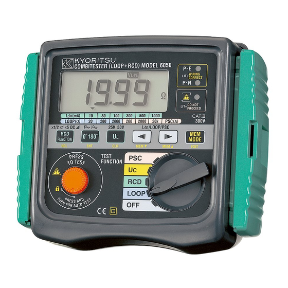
3. FEATURES 3.1 Instrument Layout Fig. 3 1..LCD 2..RCD FUNCTION SELECT SWITCH (MEMORY RECALL SWITCH) 3..0°/180°SELECT SWITCH (ENTER SWITCH) 4..UL VALUE SELECT SWITCH (MEMORY CLEAR SWITCH) 5..TEST BUTTON 6..WIRING CHECK LED LED indication of correct polarity is that the P-E and P-N LEDs are lit. -
Page 8: Test Lead
Green-Earth Fig.7 3.3 Optical Adapter Model 8212 (Optional Accessory) For Model 6050, data can be transferred to PC via Optical Adapter Model 8212. Model 8212 is supplied with PC software "KEW REPORT". Fig.8 Model 8212 operates PC/AT compatible machine on Windows 98/ME/2000/XP. -
Page 9: Test Range (Function)
IEC/EN61010-1 CATⅢ(300V)-instrument IEC/EN61010-2-031CATⅢ(600V)-test lead Protection degree: IEC60529(IP54) 3.6 Features Model 6050 has the following features: Three LEDs indicate if the wiring of the circuit ● Wiring check under test is correct. Detects overheating of the internal resistor and ● Over temperature... - Page 10 Select UL (limit of contact voltage value) 25V or 50V. Where Uc (contact voltage) exceeds ● UL value selector UL value at RCD testing, "Uc H" will be displayed without starting the measurement. When connecting Test Lead to circuit, voltage between L-PE is displayed.
-
Page 11: Specification
4. SPECIFICATION Measurement Specification Rated Voltage Test Function Range Accuracy (AC) Current L-PE : ±(3%rdg+8dgt) 20Ω +10% 230V 50Hz -15% ±(3%rdg+8dgt) L-PE : LOOP 200Ω 15mA At L-L measurement: +10% 230V 50Hz ±(3%rdg+12dgt) -15% L-L : 2000Ω 15mA ±(3%rdg+8dgt) +10% 400V 50Hz -15%... - Page 12 Rated Voltage Range Function Accuracy (AC) 100-260V 100-260V Voltage ±(2%rdg+4dgt) L-L correspouding range: L-L correspouding range: Measurement 100-440V 100-440V Accuracy Rated Voltage Function (AC) Trip Current Trip Time ×1/2 -8%∼-2% ×1 ±(1%+3dgt) +2%∼+8% L-PE : ×5 +10% 230V 50Hz -15% ±10% Auto Ramp ±4%...
- Page 13 Specifications are based on the following conditions except where otherwise stated. 1. Ambient temperature : 23±5℃ ● Reference 2. Relative humidity : 45% to 75% conditions 3. Position : horizontal 4. AC power source : 230V,50Hz 5. Altitude : Up to 2000m ●...
-
Page 14: Loop Impedance / Psc Tests
● Operating Errors of trip current (IEC 61557-6) Function Operating error of trip current ×1/2 -10%∼0% ×1 0%∼+10% ×5 0%∼+10% Auto Ramp -10%∼+10% The influencing variations used for calculating the operating error are denoted as follows: Temperature : 0℃ and 40℃ Earth electrode resistance : Earth electrode resistance(Ω) I n(mA) - Page 15 (and the prospective fault current high enough)to allow automatic disconnection of the electrical supply by the circuit protection device within a prescribed time interval. Every circuit must be tested to ensure that the earth fault loop impedance value does not exceed that specified or appropriate for the over- current protective device installed in the circuit.
- Page 16 Fig.10 In accordance with the international standard IEC 60364 for a TT system the following condition shall be fulfilled for each circuit. RA must be < _ 50/la where; RA is the sum of the resistances of the local earth system R and the protective conductor connecting it to the exposed conductor part.
- Page 17 Practical example of verification of the protection is a TT system according to the international Standard IEC 60364. Fig.11 For this example the maximum value is 1667Ω,the loop tester reads 12.74 Ωand consequently the condition RA is < _ 50/la is met. It is fundamental for this example to test also the RCD to ensure that operation takes place quickly enough to respect the safety requirement.
- Page 18 Note: ● For a distribution circuit a disconnection time not exceeding 5s is permitted. ● When the protective device is a residual current device (RCD),la is the rated residual operating current I⊿n. For instance in a TN system with a nominal voltage of Uo =230V protected by type gG fuses the la and maximum Zs values could be: Disconnecting time 5s Disconnecting time 0.4s...
- Page 19 Practical example of verification of the protection is a TT system according to the international Standard IEC 60364. Fig.12 The maximum value of Zs for this example is 2.1Ω(16amp gG fuse,0.4 seconds).The loop tester reads 1.14Ωand consequently the condition Zs < _ Uo / la is met. 5.1.2 Principles of the Measurement of Line Impedance and Prospective Short Circuit Current Line impedance is the impedance, which is measured between Phase-...
-
Page 20: Loop Impedance And Psc Testing
Method of Impedance test between Line and Neutral and Prospective Short Circuited Current test Fig.13 Method of Impedance test between Line and Line and Prospective Short Circuited Current test Fig.14 5.2 LOOP Impedance and PSC Testing 5.2.1 Preparation (1) Turn Function switch and power on the instrument. Select LOOP or PSC. - Page 21 ● LOOP range ● PSC range The Initial value LOOP Range 2000Ω PSC Range 200A 5.2.2 Wiring Check (1) Insert the Test Lead into the instrument.(Fig.15) (2) Connect test lead to object to be tested.(Fig.11,12,13,14) (3) Make sure that the P-E and P-N wiring Check LEDs are lit and the wiring in correct LED is not lit.
-
Page 22: Rcd Tests
6. RCD TESTS 6.1 Principles of Measurement The RCD tester is connected between phase and protective connectors on the load side of the RCD after disconnecting the load. A precisely measured current for a carefully timed period is drawn from the phase and returns via the earth, thus tripping the device. - Page 23 Type of RCD I⊿n 5I⊿n 40ms 300ms General(G) max. allowed Value max. allowed Value 150ms 500ms max. allowed Value max. allowed Value Selective(S) 50ms 130ms min. allowed Value min. allowed Value Typical examples of instrument connection Practical example of 3-phase + neutral RCD test in a TT system. Fig.16 Practical example of 3-phase + neutral RCD test in a TN system Fig.17...
-
Page 24: Rcd Testing
6.2 RCD Testing 6.2.1 Preparation (1) Turn Function switch and power on the instrument. Select RCD. (2) Press RCD Function switch to select RCD Function for test. Selected function will be displayed on LCD. For testing RCD's to verify that ×1/2 they are not too sensitive. - Page 25 6.2.3 Testing (1) Press the TEST BUTTON Operating time of RCD is displayed on LCD. At Auto Ramp, operating current value of RCD will be displayed. ● ×1/2....The Breaker should not trip. ● ×1....The Breaker should trip. ● ×5....The Breaker should trip. ●...
-
Page 26: Uc Tests
● The earth electrode resistance of a measuring circuit with a probe shall not exceed table1(page 12). For the RCD range of Model 6050, distortion factor of test current is improved compared with our traditional instruments. Therefore, at operating time measurement of RCD, operating time of some RCD and our traditional instruments may differ a little. -
Page 27: Auto-Test
7.2.3 Testing (1) Press the TEST BUTTON. (2) Measured result is displayed on LCD. If the measured result is 100V or more, "UcH V" is displayed on LCD. Note:When Test Lead removed during a measurement, "no" is displayed on LCD and a measurement will be stopped. Please check Test Lead is rightly connected. -
Page 28: Recall The Stored Data
(5) Decide it with ENTER SWITCH("ENT" SWITCH). Data will be stored and back to voltage measurement mode automatically. ● By pressing MEMORY MODE EXIT SWITCH ("EXIT" SWITCH) during an operation, can undo the last action. ● When making a measurement, press MEMORY MODE EXIT SWITCH("EXIT"... -
Page 29: Delete The Stored Data
(1) Firmly insert the D-SUB 9Pin female connector of Model 8212 into the socket(D-SUB 9Pin male ) of PC. (2) Insert Model 8212 into Model 6050 as shown in fig.18. Test Leads shall be removed from Model 6050 at this time. -
Page 30: Battery Replacement
● Model 8212 system requirements (1) PC/AT compatible machine on which Microsoft Windows ○ 98/ME/2000/XP can operate. (2) Pentium 233MHz or more recommended. (3) RAM 64Mbyte or more. (4) SVGA (800X600) or more. XGA(1024X768) recommended. (5) 20MB or more of free hard disk space recommended. (6) One free COM port (7) CD-ROM drive (necessary at installing) ●... -
Page 31: Servicing
11.SERVICING If this tester should fail to operate correctly, return it to your distributor stating the exact nature of the fault. Before returning the instrument ensure that:- 1. The batteries are in good condition. Please remember to give all the information possible concerning the nature of the fault, as this will mean that the instrument will be serviced and returned to you more quickly. - Page 32 DISTRIBUTOR Kyoritsu reserves the rights to change specifications or designs described in this manual without notice and without obligations. KYORITSU ELECTRICAL INSTRUMENTS WORKS, LTD. No.5-20, Nakane 2― chome, Meguro-ku, Tokyo, 152-0031 Japan Phone: (03) 3723― 0131 Fax: (03) 3723― 0152 URL:http://www.kew-ltd.co.jp...
Need help?
Do you have a question about the 6050 and is the answer not in the manual?
Questions and answers