
Summary of Contents for hamilton safe 5000 series
- Page 1 A Wholly Owned Subsidiary of Gunnebo AB 5000 Series Audio/Video System Installation & Service Manual 08-315 (4/28/16)
-
Page 2: Table Of Contents
Table of Contents Description.....................3 System Configuration..................3 Cable Considerations..................4 Matrix Installation..................4 Matrix / System Wiring Diagram..............5 Cat 5 Lane Speaker/Driver Kit Installation............6 Wireless Headset Installation.................7 E10052 Wireless Expansion Adapter.............8 5512 Remote Handset Installation..............8 5012 Remote Handset Installation...............10 5570 / 5571 Remote Customer Audio Consoles..........11 5572 / 5573 Remote Customer “In Wall”... -
Page 3: Description
Description The 5000 Series system consists of components that allow 2-way audio and video communications between server (teller) consoles and customer units in banks, pharmacies and other service environments. These systems allow both parties to hear and speak at the same time without feedback. -
Page 4: Cable Considerations
Cable Considerations Be sure to use the proper cable for connecting the matrix to the customer lanes. For audio it is HIGHLY RECOMMENDED to use Hamilton cable (E0680) for distances up to approximately 180 feet. This cable contains a 16AWG twisted pair for the speaker, a 20AWG twisted pair for the call button and a 20AWG twisted, shielded pair for the microphone. -
Page 5: Matrix / System Wiring Diagram
Matrix / System Wiring Diagram Refer to the drawing below for standard wiring connections. The drawing shows a 4-lane matrix but the same wiring applies to all versions. Observe the following guidelines. The ground wire connection shown for the audio matrix is not required for the 5003 matrix. Be sure to only connect the drain wire for the microphone pair at the matrix end as shown. -
Page 6: Cat 5 Lane Speaker/Driver Kit Installation
Cat 5 Lane Speaker/Driver Kit Installation The Cat 5 Lane Speaker Driver Kit (E0958-KIT) allows for the use of Cat 5 cable from the matrix to the customer lane for distances up to 1000 feet. Cat 5e & Cat 6 may also be used. Volumes must be kept low when using this kit. -
Page 7: Wireless Headset Installation
Wireless Headset Installation The following instructions apply to Plantronics CS540, CS50 & CS55 Wireless Headsets. There are many other wireless headsets on the market and many of these will most likely work fine but compatibility cannot be guaranteed. Wireless headsets can be used on 5501, 5001 & 4001 Series consoles. -
Page 8: E10052 Wireless Expansion Adapter
5012H (side mount) handsets. It provides customer privacy and can be used with 4000 and 5000 Series audio systems. The only operational difference is removing the handset of the 5512 from its cradle does not initiate a Teller Call like the 5012 did; a local call button must be used for this purpose. - Page 9 The Model 5512 can be wall mounted or mounted to the side of pneumatic tube drive-up units if desired. Handsets that are used outdoors should be protected from direct rain. Installation 1) Remove the 4 screws from the lid of the enclosure. This makes mounting the enclosure easy since the entire contents are removed with the lid.
-
Page 10: 5012 Remote Handset Installation
5012 Remote Handset Installation The 5012 Remote Handset has been replaced with the 5512 but is described here for service purposes. With the 5012, removing the handset from its cradle initiates a Teller Call and disconnects the remote station speaker and microphone. Important Note: The handset used with the 5012 is different from the 5512 handset. -
Page 11: 5570 / 5571 Remote Customer Audio Consoles
5570 / 5571 Remote Customer Audio Consoles Description The 5570 & 5571 Remote Customer Audio Consoles consist of a speaker, microphone and call button in a desktop type enclosure for indoor applications. The 5570 is intended for use with standard audio cable and can be used for cable lengths up to approximately 180 feet. -
Page 12: 5572 / 5573 Remote Customer "In Wall" Audio Units
5572 / 5573 Remote Customer “In Wall” Audio Units Description The Remote Customer “In Wall” Audio Unit consists of a speaker, microphone and call button in a recess mount double gang electrical box for indoor applications. The model 5572 is intended for use with standard E0680 audio cable and can be used for cable lengths up to approximately 180 feet. - Page 13 Cable Connector Socket 12VDC Power Supply Socket (center pin positive) Leave pot set fully counter clockwise RJ45 Connector for Cat 5 Cable 5572 5573 08-315 (4/28/16)
-
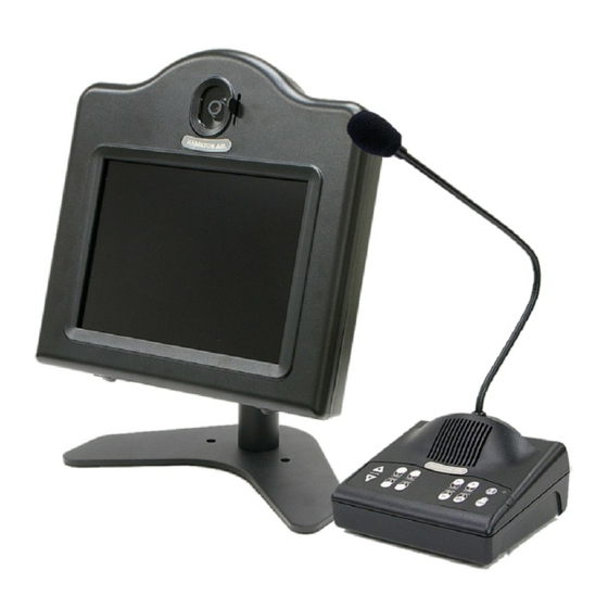
Page 14: 5550 Teller Video Unit Installation
5550 Teller Video Unit Installation The following instructions are for the current style 5550 which contains both a camera and 10.4” LCD monitor for two way video. The 5550-1 is the same unit without a camera installed for one way video. Installation Separate the video head from the stand by removing 4 screws as shown in the photo. - Page 15 Service Adjustments A momentary service/mirror switch on the bottom left side of the video head disconnects the external wiring and internally connects the camera to the monitor for testing purposes. The service/mirror switch does not exist on the 5550-1 since no camera is present. he monitor has been adjusted at the factory but a menu board allows settings to be changed if needed.
-
Page 16: 5650 Teller Video Unit Installation
5650 Teller Video Unit Installation The following instructions are for the 5650 which contains both a camera and 15” LCD monitor for two- way video. The 5650-1 is the same unit without a camera installed for one-way video. Cable Connections Remove the back cover from the stand by pulling out from the top of the cover. - Page 17 Service Adjustments The Select button on the side of the monitor is used to select the appropriate input. It should be set for AV. If the image on the screen displays “SV - No Signal” or “VGA - No Signal” press the select button to set the input back to AV.
-
Page 18: 5517 Remote Video Unit Installation
5517 Remote Video Unit Installation The 5517 Remote Video Unit (10.4” LCD) requires 12VDC at approximately 2A to operate properly. This requires that power be provided directly at the pneumatic unit to avoid the power drop associated with long wire runs. Each 5517 is supplied with a power supply. An optional Video Power Control Kit (E0885), ordered separately, can be used to control the relay board in each video head so the monitors, and optionally the cameras, can be turned off when desired. - Page 19 Connect the monitor cable to the top left BNC connector and the camera cable to the top right BNC connector in the video head as labeled. Connect the power supply cable and the relay trigger wires to the relay board in the video head as shown in the section “E0885 Video Power Control Kit Installation”.
-
Page 20: 5617 Remote Video Unit Installation
5617 Remote Video Unit Installation The 5617 Remote Video Unit (15” LCD) is ordered either as a post mount or side mount version. The post mount version includes a 3” (square) x 36” post. The side mount unit includes an arm for attaching to the top of a pneumatic unit. - Page 21 extended cable to the trigger terminals per the drawing. The trigger terminals and J3 on the relay module are common. If the 5617 includes audio, connect the speaker wires to the black/white twisted pair and the microphone wires to the shielded cable.
-
Page 22: E0885 Video Power Control Kit Installation
E0885 Video Power Control Kit Installation The E0885 kit should only be used to control the power through the relay boards in the 5517 / 5617 video units as shown. DO NOT attempt to power video units directly with the power control kit. Follow the wiring diagram below. -
Page 23: 5550/5517 Lcd Menu Adjustments
5550/5517 LCD Menu Adjustments Four types of LCD screens have been used to manufacture 5550 and 5517 video units. Refer to the appropriate menu button arrangement below for tips on navigating the menu. This menu board is located below the LCD screen. A dual color LED on the right side of the board indicates power status: green = on &... -
Page 24: E0465-3Wd-Lp License Plate Camera Kit Installation
E0465-3WD-LP License Plate Camera Kit Installation The following instructions are for mounting the License Plate Camera assembly on the back side of a 5517 Video Unit. This camera is used for viewing the rear license plate of a vehicle as it leaves the drive-up lane. -
Page 25: Audio Matrix Switch Settings
The “off” position with these consoles is actually “on partial”. MIC DC Switches: These switches only exist on older 5000 Series audio matrixes and are used to determine if the lane microphone is a Dynamic (UP) or Electret Condenser (DOWN) type. Since the electret type is standard (and recommended) this switch must be down or the mic will not work. -
Page 26: Video Matrix Switch Settings
Video Matrix Switch Settings Refer to the chart below for the dip switch pack located on the end of the video matrix. Factory settings are shown in bold. Feature Switch # Up (Off) Down (On) Driveway Only All Cameras Idle Console View Normal Static Aux. -
Page 27: Adjusting The Audio System
Adjusting the Audio System The speaker (SPK) and microphone (MIC) pots on the audio matrix provide the main volume adjustment for the system. (See the drawing in the section “Matrix / System Wiring Diagram”.) There are a set of pots for each customer lane. The speaker pot adjusts the outgoing volume to the customer lane while the microphone pot adjusts the incoming volume to the teller. -
Page 28: Mixing 5501 Series Consoles With Different Firmware Revisions
Mixing 5501 Series Consoles With Different Firmware Revisions Audio adjustment issues often occur when 5501 series consoles with different firmware revisions are mixed on the same system due to the difference in outgoing volume. The firmware revision is identified on the serial number label above the bar code. The label is on the bottom of the console. The following provides a guide for adjusting the mic gain on each console so the volume levels are very close. -
Page 29: Changing The Call Tone Type & Volume
Changing the Call Tone Type & Volume The call tone type and volume are system wide parameters which are stored in the audio matrix. Any audio console in the system can be used to change these parameters as follows. Press the LANE 1 key and the HOLD key at the same time. Lane 1 & 2 indicators light orange. Press the LANE 2 key to rotate through the call tone types until the desired tone is heard. -
Page 30: System Operating Instructions
System Operating Instructions Each lane key on the audio console has an indicator light. Interpret the lights as follows. RED (fast flash)......Customer CALLING for service GREEN (steady)......Customer in 2-WAY CONTACT with your console RED (steady)........Customer in 2-WAY CONTACT with another console GREEN (slow flash)....Customer placed on HOLD from your console RED (slow flash)......Customer placed on HOLD from another console Operate the Teller Console as follows. -
Page 31: Echo Canceller & Background Noise Cancellation
In effect, the teller hears their own voice. The echo cancellation circuitry in 5000 Series consoles is designed to eliminate this issue. The echo canceller can have either dynamic or fixed learning. Dynamic learning adjusts for the best possible cancellation setting while a lane is selected. -
Page 32: Troubleshooting Tips
Troubleshooting Tips System won’t initialize (console lights continue to blink red or stay lit) – The audio consoles, audio matrix and video matrix all communicate by RS-485 through the Cat 5 cables. A problem with any of these devices can cause a system wide problem like this. Power down and disconnect all but one audio console –... -
Page 33: Frequently Asked Questions
occasionally get into a state where it will not work – it may just produce loud static. To clear this condition put the headset through a reset as follows: 1. Press both the talk button and the mute control button on the headset for 5 seconds. The mute control is the volume dial pressed in. - Page 34 Sound bouncing off the customer vehicle contributes to this. 5000 Series consoles have an echo canceller feature which reduces the effect of this condition. See the section “Echo Canceller & Background Noise Cancellation”...
- Page 35 If a 3000 Series matrix is being used, it is recommended to only use 3000 Series consoles. A 5000 Series console may have issues at times such as a delay when selecting a lane or having to select a lane twice before it works. A 4000 Series console may completely lock up.
- Page 36 channel connectors allow for connection to a stereo source but they will be mixed together for a mono output at the customer lane. If a mono source is used, either input on the matrix can be used. Q. The console cable that ships with each audio console is too short for a particular installation. Can I make a longer cable without causing problems? A.
- Page 37 Q. Is it possible to use audio and video matrixes from different series together on the same system? A. 4000 and 5000 Series audio and video matrixes can be interchanged. 3000 Series audio matrixes can only be used with 3000 Series video matrixes since the communications and cabling are different.
- Page 38 Q. What are the requirements for the auxiliary video input on the video matrix? A. This input requires an industry standard 1V peak-to-peak composite video signal, the same as the output from a CCTV camera. Typical sources for this signal are a media player, the video output of a DVR or a computer that has a video card with a composite video output.
- Page 39 Q. The monitors in 5550 Teller Video Units or 5517 Remote Video Units were working but now I cannot get a picture. What could be wrong? A. If a blue box appears on the screen with a message that says “AV No Signal”, the monitor is working but it is not receiving a video signal.
-
Page 40: Hamilton Audio/Video Part Numbers
Hamilton Audio/Video Part Numbers The number preceding the part number indicates the photo which follows this listing. Audio Consoles 5501-2......2 Lane Audio Console w/Cable 5501-4......4 Lane Audio Console w/Cable 5501-8......8 Lane Audio Console w/Cable 5501-12......12 Lane Audio Console w/Cable 5501-1......Kit, 1 on 2 Audio System (5501-2 w/5003 & Power Supply) Audio Console Parts &... - Page 41 Lane Audio E0680......Audio Cable (sold in 1000’ spools) E0604......Lane Microphone w/48” Cable E10064......Lane Microphone w/48” Cable & IDC Connector (for pneumatic I/O board) E0205-1.......Lane Microphone w/6” Leads E0604-DD....Deal Drawer Mic Assembly w/Grommet Kit H10305......Grommet Kit (part of E0604-DD) E10330......Lane Microphone Assembly for HA1000-XLR (similar to E0604-DD except w/IDC connector) E10188......External Deal Drawer Microphone w/15’...
- Page 42 Video Accessories HCBWDHR25 (NLA). Honeywell Camera w/2.9mm Lens (replacement for 5517 ver. 1.5 & lower & 5517-SUN ver. 1.3 & lower) - (NLA replace with Ikegami ISD-A14-25-ACDC but requires new mounting holes in bracket so lens does not hit the glass) ISD-A14-29....Ikegami Camera w/2.9mm Lens (replacement for 5517 ver.
-
Page 43: Part Number Photos
Part Number Photos Audio Consoles (1) 5501-2 (2) 5501-4 (3) 5501-8 (4) 5501-12 (5) 5501-1 (KIT) Audio Console Parts & Accessories (6) E0894 (7) E0605 (8) WS311754 (9) 802-420-5000 (10) E0764 (11) B6077 (12) 5501-HWB (13) 5501-VWB (14) B6074-KITB 08-315 (4/28/16) - Page 44 Matrixes (15) 5003 (16) 5004 (17) 5002-4 (18) 5002-8 (19) 5002-12 (20) 5006 (21) 5005-4 (22) 5005-8 (23) 5005-12 08-315 (4/28/16)
- Page 45 Lane Audio (24) E0680 (25) E0604 (26) E0604-DD (27) E10188 (28) E0957 (29) E10184 (30) E10226 (31) B4956 (32) E0958-KIT (33) 5570 / 5571 (34) 5572 / 5573 Headsets & Handsets (35) CS540 (36) 5014 (37) E10052 (38) 5512 08-315 (4/28/16)
- Page 46 Video Units (39) 5550 (40) 5550-1 (41) 5517 / 5517-SUN (42) 5650 (43) 5650-1 (44) 5617A..Arm or Post Not Shown (45) E0465-3WD (46) E0465-3WD-LP Video Accessories (47) H3655 (48) B6712 08-315 (4/28/16)
- Page 47 (49) B6911 (50) B10023 (51) E10039 Power Supplies & Accessories (52) E0736 (53) E10171 (54) E10234 (55) E10233 (56) E10159 (57) ACDC-2412-300 (58) E10036 (59) E0885 (60) E0740 (61) E0737 08-315 (4/28/16)
- Page 48 7775 Cooper Road Cincinnati, OH 45242 Phone: 513-874-3733 A Wholly Owned Subsidiary of Gunnebo AB www.hamiltonsafe.com For tech support on these products call 513-795-5332 08-315 (4/28/16)
Need help?
Do you have a question about the 5000 series and is the answer not in the manual?
Questions and answers