Table of Contents
Advertisement
Advertisement
Table of Contents
Troubleshooting

Related Manuals for Paradise Datacom 205486 REV F


Summary of Contents for Paradise Datacom 205486 REV F
- Page 1 Teledyne Paradise Datacom LLC 328 Innovation Blvd., Suite 100 State College, PA 16803 USA Email: sales@paradisedata.com 208495 REV B Compact Outdoor Solid State Power Amplifier Operations Manual Phone: Fax: Web: www.paradisedata.com ECO 16449 (814) 238-3450 (814) 238-3829 08/30/2011...
- Page 2 No part of this document may be reproduced or transmitted in any form without the written permission of Teledyne Paradise Datacom LLC. All rights are reserved in this document, which is property of Teledyne Paradise Datacom LLC. This document contains proprietary information and is supplied on the express condition that it may not be disclosed, reproduced or transmitted in any form without the written permission of Teledyne Paradise Datacom LLC.
-
Page 3: Table Of Contents
Section 1: General Information ... 11 1.0 Introduction ... 11 1.1 Description ... 11 1.2 Specifications ... 11 1.3 Equipment Supplied ... 11 1.4 Safety Considerations ... 12 1.4.1 High Voltage Hazards ... 12 1.4.2 RF Transmission Hazards ... 12 Section 2: Installation ... - Page 4 3.4.1.1 Signal Indicators ... 34 3.4.1.2 Fault Status Indicators ... 35 3.4.1.3 Voltage, Current and Temperature Display ... 36 3.4.1.4 Gain Adjustment ... 36 3.4.1.5 RF Power Indicator ... 36 3.4.2 Universal M&C Settings Window ... 37 3.4.2.1 Power Up Settings ... 37 3.4.3 IP Setup Window ...
- Page 5 9.1.2 Software Setup ... 79 9.1.2.1 Stand-Alone 1:1 Redundant System ... 79 9.1.2.2 PC Control using RS232 and Paradise M&C Software ... 82 9.1.2.3 PC Control using RS-485 and Paradise M&C Software ... 87 9.2 1:2 Redundant Systems ... 89 9.3 1:2 Redundant Systems with L-Band Input ...
- Page 6 Section 10: Fixed Phase Combined Redundant Systems ... 97 10.0 Phase Combining Overview ... 97 10.1 1:1 Fixed Phase Combined System Components ... 99 10.1.1 Signal Box Assembly ... 99 10.2 1:1 Fixed Phase Combined System Operation with the FPRC-1100 ... 101 10.3 1:1 Fixed Phase Combined System with L-Band Input ...
- Page 7 Figure 3-18: Enter IP address for Compact Outdoor SSPA (default is 192.168.0.9) 41 Figure 3-19: M&C Applet loading into browser window ... 41 Figure 3-20: Enter password (default is “paradise”) ... 42 Figure 3-21: Status and Faults window descriptions ... 42 Figure 3-22: Communication Settings window descriptions ...
- Page 8 Figure 9-9: Add New Compact Outdoor SSPA window... 83 Figure 9-10: Individual SSPA Operation Window ... 83 Figure 9-11: Paradise Datacom Universal M&C, Add Unit Menu Tree... 84 Figure 9-12: Add 1:1 Redundant System Window ... 84 Figure 9-13: Redundant Control Panel showing configured 1:1 Redundant System 85 Figure 9-14: Dialog window, Affirm mute of on-line amplifier ...
- Page 9 Figure 11-9: GetIF Application Parameters Tab ... 137 Figure 11-10: Getif MBrowser window, with update data in output data box ... 137 Figure A-1: Ethernet Quick Start Cable ... 139 Figure A-2: RS-232 Quick Start Cable, 207998 ... 140 Figure B-1: Mixed Redundant System using New and Old CO Amplifiers ... 141 Figure B-2: Redundant System using RCP2-1100 Controller ...
- Page 10 THIS PAGE INTENTIONALLY LEFT BLANK 208495 REV B Operations Manual, HPA2, Compact Outdoor SSPA...
-
Page 11: Section 1: General Information
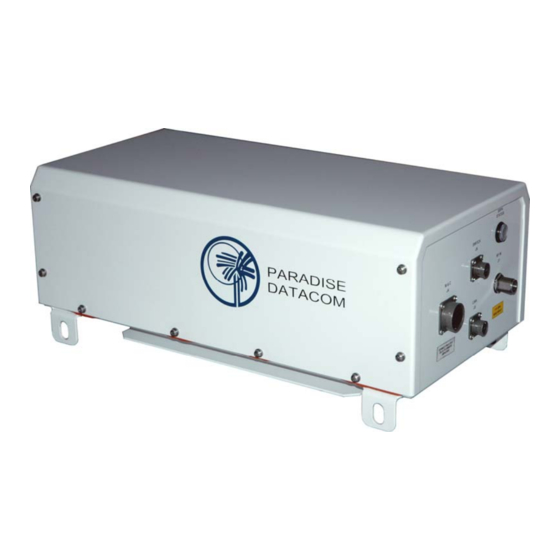
1.0 Introduction This section provides the general information for the Teledyne Paradise Datacom LLC line of Compact Outdoor Solid State Power Amplifiers. The Compact Outdoor SSPA has been designed and manufactured to be an extremely robust and reliable amplifier. It is well suited for harsh outdoor environments. -
Page 12: Safety Considerations
• Product Guide CD with SSPA Monitor & Control Software • M&C (J4) Mating Connector, MS3116F18-32P • Waveguide gaskets (dependent on frequency band) • Sealing tape (87F730) 1.4 Safety Considerations Potential safety hazards exist unless proper precautions are observed when working with this unit. -
Page 13: Section 2: Installation
Table 2-2. An option for 110 VAC prime power is available for the higher-powered units. WARNING! Always terminate the RF input and output connectors prior to applying prime AC input power! Operations Manual, HPA2, Compact Outdoor SSPA Teledyne Paradise Datacom LLC 328 Innovation Park, Suite 100 State College, PA 16803 Phone:... -
Page 14: Table 2-2: Compact Outdoor Amplifier Prime Power Summary
Table 2-2: Compact Outdoor Amplifier Prime Power Summary Band Model HPAC2030ACXXXXX HPAC2040ACXXXXX HPAC2050ACXXXXX HPAC2075ACXXXXX HPAC2100ACXXXXX HPAC2140ACXXXXX HPAC2200ACXXXXX HPAC2250ACXXXXX HPAC2300ACXXXXX HPAK2010ACXXXXX HPAK2020ACXXXXX HPAK2025ACXXXXX HPAK2035ACXXXXX HPAK2040ACXXXXX HPAK2050ACXXXXX HPAK2070ACXXXXX HPAK2100ACXXXXX HPAK2125ACXXXXX HPAKG200ACXXXXX HPAX2060ACXXXXX HPAX2075ACXXXXX HPAX2100ACXXXXX HPAX2140ACXXXXX HPAX2200ACXXXXX HPAX2250ACXXXXX HPAS2050ACXXXXX HPAS2100ACXXXXX HPAS2200ACXXXXX** HPAS2200ACXXXXX*** HPAS2300ACXXXXX** HPAS2300ACXXXXX*** HPAS2050BCXXXXX HPAS2100BCXXXXX... -
Page 15: Dc Input Option [Ms3102E-20-29P]
2.3 DC Input Option [MS3102E-20-29P] The Compact Outdoor Amplifier can also be configured with a DC Input Voltage power supply. The DC Input Voltage can range from 42-60 VDC. When using a DC input voltage the input power connector, J7, is configured per Table 2-3. Table 2-3: DC Input Connector, MS3102E-20-29P Pin # on J7 Connection... -
Page 16: Rf Input (J1) [N-Type (F)]
2.5.1 RF Input (J1) [N-type (F)] The RF Input connector is a type N female connector. Nominal RF input levels are approxi- mately -28 dBm depending on the output power level of the unit. The maximum allowable RF input signal should be limited to +15 dBm. Figure 2-2 shows the input side of the Compact Outdoor Amplifier. -
Page 17: Switch Port (J6) [Ms3112E10-6S]
2.5.4 Switch Port (J6) [MS3112E10-6S] When used in a 1:1 redundant system, the waveguide switch must be connected to the switch port of each amplifier (MS3112E10-6S). See Table 2-5. It mates with MS3116F10-6P. Pin # on J6 Connection 2.5.5 RF Output (J2) The RF Output is brought out through waveguide in the Compact Outdoor Amplifier. -
Page 18: Rf Output Sample Port (J3) [N-Type (F)]
Figure 2-4: Bottom View, Compact Outdoor Amplifier 2.5.6 RF Output Sample Port (J3) [N-type (F)] The RF Output Sample port, J3, is located on the bottom of the amplifier as shown in Figure 2-4. This connector provides a -40 dBc sample of the amplifier’s output signal. It is a N-type female connector. -
Page 19: Airflow
2.6 Airflow The air intake and exhaust are both located on the bottom side of the amplifier. The intake is brought through three fans while the exhaust is along the two rows of heatsink fins as seen in Figure 2-4. A minimum clearance of 6 inches (152 mm) should be maintained between the bottom of the amplifier and any mounting surface. -
Page 20: Table 2-7: Compact Outdoor Sspa Weights
Table 2-7: Compact Outdoor SSPA Weights Band Model HPAC2030AC... HPAC2040AC... HPAC2050AC... HPAC2075AC... HPAC2100AC... HPAC2140AC... HPAC2200AC... HPAC2250AC... HPAC2300AC... HPAK2010AC... HPAK2020AC... HPAK2025AC... HPAK2035AC... HPAK2040AC... HPAK2050AC... HPAK2070AC... HPAK2100AC... HPAK2125AC... HPAX2060AC... HPAX2075AC... HPAX2100AC... HPAX2140AC... HPAX2200AC... HPAX2250AC... HPAS2050AC... HPAS2100AC... HPAS2200AC... HPAS2300AC... HPAKA040AC… HPAKA080AC... Base Weight With zBUC lbs (kg) lbs (kg) -
Page 21: Compact Outdoor Mounting Kit Installation
2.8 Compact Outdoor Mounting Kit Installation These instructions outline how to install a Teledyne Paradise Datacom Compact Outdoor SSPA unit onto an antenna boom, using a Universal Compact Outdoor Mounting Kit. This kit allows installation of the Compact Outdoor SSPA on antenna booms up to 10” thick. -
Page 22: Figure 2-6: Bolt Mounting Bracket To Unit
2.8.3 Installation 1. Locate the mounting studs on the bottom of the Compact Outdoor SSPA unit. Using a ½” bolt, two flat washers, and a ½” nut, firmly bolt one mounting bracket to each mounting stud, as shown in Figure 2-6. Be sure each bracket is vertical, and the top flange of the mounting bracket points away from the unit. -
Page 23: Figure 2-8: Co Mount Completed
3. Bring the unit up tight under the boom (with the long axes parallel), sliding the All-Thread studs past the sides of the boom to show above the boom top. Place the remaining pieces of Uni-strut (open channel down) across the boom, onto the protruding All-Thread stud ends. - Page 24 THIS PAGE INTENTIONALLY LEFT BLANK 208495 REV B Operations Manual, HPA2, Compact Outdoor SSPA...
-
Page 25: Section 3: Quick Start & Operation
3.0 Introduction The Compact Outdoor SSPA is available with a standard RS232/485 serial communications interface or an optional Ethernet & RS232/485 interface. This section summarizes the connections to a remote computer for various remote communications. Table 3-1 summarizes the hardware connections of Port J4 for Ethernet-capable units; Table 3-2 displays the hardware connections of Port J4 for non-Ethernet-capable units. -
Page 26: Legacy Compact Outdoor Sspas
Isolated Return for RS232/RS485 Figure 3-2: J4 Connections for RS-485 Communications Isolated Return for RS232/RS485 Figure 3-3: J4 Connections for RS-232 Communications 3.0.2 Legacy Compact Outdoor SSPAs Compact Outdoor SSPAs with serial numbers of less than 300,000 did not include isolated grounds for RS-232/RS-485 serial communications. -
Page 27: Compact Outdoor Sspas In Legacy Systems
9600 BAUD Selection shown Figure 3-5: J4 Connections for RS-232 Communications for Serial Numbers <300,000 3.0.3 Compact Outdoor SSPAs in Legacy Systems The isolated return for RS-232/RS-485 systems that exists on Compact Outdoor SSPAs with serial numbers 300,000 and above will require an additional connection on J4 when used in systems that have Monitor and Control cables designed to be used with units with serial numbers <... -
Page 28: Port J4 Pin-Outs
3.1 Port J4 Pin-Outs Table 3-1 shows the pin-outs for the J4 Monitor & Control Connector for Ethernet capable units. Table 3-1: Monitor & Control Connector (J4) Pin-Out (Ethernet capable) Signal Type Mute Input Closure to Ground Auxiliary Input Closure to Ground Summary Alarm Form C Relay Auxiliary Alarm... -
Page 29: Table 3-2: Monitor & Control Connector (J4) Pin-Out (Non-Ethernet)
Table 3-2 shows the pin-outs for the J4 Monitor & Control Connector for units that cannot communicate via Ethernet (units with serial numbers prior to 300,000). Table 3-2: Monitor & Control Connector (J4) Pin-Out (Non-Ethernet) Signal Type Mute Input Closure to Ground Auxiliary Input Closure to Ground Summary Alarm... -
Page 30: Quick Start Cables
3.2 Quick Start Cables For convenience all Compact Outdoor Amplifiers ship with a ‘Quick-Start’ communications cable. This allows the user to immediately connect the amplifier to a PC and begin operation. Ethernet ready units ship with a Quick Start cable fitted with a 10-base T connector as shown in Figure 3-7. -
Page 31: Quick Start Connections
This section describes the necessary steps to communicate with a Compact Outdoor SSPA using either the Ethernet or RS-232 Quick Start cables and the Universal M&C Software. The Teleydne Paradise Datacom Universal M&C Software is a free Windows-based application that can be downloaded from the company web site, www.paradisedata.com. -
Page 32: Quick Start Rs-232 Connection
COM ports on your computer. This connection will unmute the amplifier. Review the cable schematic in Figure 3-8. 6. Launch the Windows-based Teledyne Paradise Datacom Universal M&C Software. NOTE: If the Compact Outdoor unit is powered up with the RS-232 Quick... -
Page 33: Universal M&C Operation
3.4 Universal M&C Operation 1. Run the Teledyne Paradise Datacom Universal Monitor and Control Program from the Programs Menu of your PC. 2. Select [Action] → [Add Unit] from the main menu of the Universal M&C Program and select [Compact Outdoor SSPA] from the menu choices. See Figure 3-9. -
Page 34: Universal M&C Status Window
3.4.1.1 3.4.1.2 Figure 3-11: Universal M&C Status Window 3.4.1 Universal M&C Status Window The Universal M&C Software will initialize and open to the Status Window, the main monitoring display. See Figure 3-11. The Status Window shows the the current conditions (or state) of the Compact Outdoor SSPA. -
Page 35: Fault Status Indicators
Figure 3-12: Fault Indicators 3.4.1.2 Fault Status Indicators The Fault Status frame in the lower left side of the Status Window contains a 3x4 grid of SSPA fault lights. See Figure 3-12. Summary Alarm: The Summary Alarm is simply a logical ‘OR’ of any of the alarm indicators. Low DC Current Alarm: The Current Fault is factory preset to alarm if the SSPA module current falls below 60% of its nominal value. -
Page 36: Voltage, Current And Temperature Display
3.4.1.3 Voltage, Current and Temperature Display On the right side of the Status window there is a thermometer display that reports the present baseplate temperature of the amplifier. The baseplate temperature typically experiences a 20-30 degree rise above ambient on the highest power Compact Outdoor amplifiers and 15-20 degree rise on lower power units. -
Page 37: Universal M&C Settings Window
3.4.2 Universal M&C Settings Window Figure 3-13 shows the ‘Settings’ window of the Teledyne Paradise Datacom Universal M&C Software. The ‘Settings’ window contains many of the global settings that are available in the SSPA. 3.4.2.1 Power Up Settings The Compact Outdoor amplifier will power up with the “last-state” settings before the unit was powered down. -
Page 38: Figure 3-14: Spare Fault Wizard
Baud Rate Select: Sets the baud rate of the unit. The supported baud rates include: 2400, 4800, 9600, 19200, and 38400 baud. The factory default baud rate is 9600. You will be asked to verify that you wish to change the Baud Rate. -
Page 39: Ip Setup Window
[14] Fault Setups: The user may also adjust the Spare, Auxiliary, BUC, and Forward RF Fault Status and Handling via the appropriate pull-down menus on the Settings Window. Spare/Auxiliary/BUC/Forward RF Fault Handling: Selects whether the associated fault should be a major or minor fault, and whether the fault should mute the unit. -
Page 40: Universal M&C Preferences
3.4.4 Universal M&C Preferences The user can adjust certain preferences of the Universal Monitor and Control Software. See Figure 3-16. Queries: Enable and adjust the interval that the software queries the unit. Note that if queries are disabled, there will be no communication with the unit at startup. Logs: Enable and adjust the interval that the software writes to the log. -
Page 41: Web-Based M&C
3.5 Web-based M&C The most basic method of communication with the Compact Outdoor SSPA is via a web browser, which accesses the built-in web pages served from the amplifier’s embedded web server. Supported web browsers include Internet Explorer version 6 or better, and Mozilla Firefox version 3.0.3 or better. -
Page 42: Navigating The Web M&C
As the applet loads, the user will be prompted to enter a password. The default password is paradise (see Figure 3-20), but the user may assign a new password using the web M&C or Teledyne Paradise Datacom’s Universal M&C Software. See Section the Universal M&C Software. -
Page 43: Figure 3-22: Communication Settings Window Descriptions
Enter relevant IP Settings for user’s network; Click ‘Change IP’ button to change. Click ‘Read IP’ button to populate current IP settings. Figure 3-22: Communication Settings window descriptions • Communication Settings Window: Read/Write listing of adjustable SSPA communication parameters. All options are selectable. To set a parameter, select the new value and click the “Change”... -
Page 44: Figure 3-23: General Settings Window Descriptions
Select Single or Redundant Mode. Select HPA1, HPA2 or HPA3. Select Startup State: Online or Standby. Select Standby Mode: Hot or Cold Standby. Figure 3-23: General Settings window descriptions • General Settings Window: Displays the SSPA Redundancy and BUC/Amplifier Settings. See Figure 3-23 for descriptions of the contents of the General Settings window. -
Page 45: Figure 3-24: Fault Settings Window Descriptions
Select “Ignore”, “External Mute”, or “ADC Channel 0-7”. Select “Minor Fault”, “Major Fault” or “Major Fault + Mute”. Select Minimum and Maximum Values; Click ‘Confirm’ to set. Select “Ignore”, “LogicHigh” or “LogicLow”. Select “Minor Fault”, “Major Fault” or “Major Fault + Mute”. Figure 3-24: Fault Settings window descriptions •... - Page 46 THIS PAGE INTENTIONALLY LEFT BLANK 208495 REV B Operations Manual, HPA2, Compact Outdoor SSPA...
-
Page 47: Section 4: Operation
(SSPA) module. It has a full compliment of parallel I/O monitor and control signals as well as serial I/O capability using a PC and host communication software from Teledyne Paradise Datacom LLC. Proprietary thermal management techniques allow even the highest output power level ampli- fiers to operate reliably in environments up to 60°C ambient temperature and 100% relative... -
Page 48: Ac / Dc Converter
4.1 AC / DC Converter The prime AC input power is delivered to a switching converter module that produces 300 VDC. This module is an auto-sensing, power factor corrected front end that has proven reli- ability and allows the amplifier system to operate over a wide variety of input power conditions encountered around the world. -
Page 49: Rf Output (J2)
For example, if a 50 W Ku Band Compact Outdoor amplifier is used in a system it has a P 47.0 dBm. Therefore the maximum input power should be limited to -28 dBm. Slightly higher input power levels will not damage the amplifier but will result in higher levels of distortion in the output signal. -
Page 50: Open Collector Alarm Outputs (J4)
Gain Adjust Control J4-Pin A. The gain is also adjustable using a host PC and the supplied Teledyne Paradise Datacom Universal Monitor and Control program. See the Serial I/O Section for details on Serial Control. -
Page 51: Serial I/O Control (J4)
4.3.8 Serial I/O Control (J4) For serial data control of the Compact Outdoor SSPA, a Windows-based Monitor &Control program is supplied with the amplifier that allows all of the control and alarm functionality over a serial communication link. Both RS-232 and RS-485 can be used to communicate with the amplifier. The amplifier default is to operate on RS-485 but can easily be set to RS-232 by pulling the RS-232/RS-485 Select line low. -
Page 52: Figure 4-2: Schematic, Non-Ethernet Compact Outdoor Sspa
Figure 4-2: Schematic, Non-Ethernet Compact Outdoor SSPA 208495 REV B Operations Manual, HPA2, Compact Outdoor SSPA... -
Page 53: Figure 4-3: Schematic, Ethernet Capable Compact Outdoor Sspa
Figure 4-3: Schematic, Ethernet capable Compact Outdoor SSPA Operations Manual, HPA2, Compact Outdoor SSPA 208495 REV B... -
Page 54: Figure 4-4: Schematic, 48 Vdc Ethernet Compact Outdoor Sspa
Figure 4-4: Schematic, 48 VDC Ethernet Compact Outdoor SSPA 208495 REV B Operations Manual, HPA2, Compact Outdoor SSPA... -
Page 55: Section 5: L Band Operation
FSK communications for remote M&C capability. The FSK is a 650 KHz signal that is multi- plexed onto the L-Band input of the unit. The ZBUC converter utilizes Teledyne Paradise Datacom’s proprietary “Smart Reference Technology”. Smart Reference Technology allows the system user to change reference frequency and power level or choose internal or external reference without requiring any system configuration. -
Page 56: Zbuc Features
SSPA. 5.1 ZBUC Features This section describes the features available in the Teledyne Paradise Datacom ZBUC con- verter. The ZBUC converter is available as an option for the Compact Outdoor SSPA, and is available in four C-Band models, two Ku-Band models, one X-Band model, and one Ka-Band model. -
Page 57: Zbuc Converter Theory Of Operation
5.3 Smart Reference Technology Teledyne Paradise Datacom’s new ZBUC converter comes standard with smart reference technology. Smart reference technology allows the system operator to change external system reference frequency without any system configuration required. The ZBUC converter will automatically sense and lock to any one of the following system reference frequencies: 5, 10, 20, 25, and 50 MHz. -
Page 58: Zbuc Fsk Monitor And Control
Deviation Tolerance Locking Range Input Level Range Start Tone Time See Teledyne Paradise Datacom document number 201410 for a full description of the VSAT BUC Protocol. ≤±1 • 10 over the temperature range -40 to +90 °C ≤±1 • 10 aging per day ≤±5 •... -
Page 59: Typical System Configuration
5.5 Typical System Configuration This section shows the Compact Outdoor SSPB in a common system application. Figure 5-3 shows the Compact Outdoor used with a Teledyne Paradise Datacom Evolution Series PD25 modem. Indoor Equipment RS485 M&C Figure 5-3: Compact Outdoor SSPB with PD25 Evolution Modem 5.6 IFL Cable Considerations... - Page 60 THIS PAGE INTENTIONALLY LEFT BLANK 208495 REV B Operations Manual, HPA2, Compact Outdoor SSPA...
-
Page 61: Section 6: Fiber-Optic Option
1000 can be handled through front panel operation or remotely via parallel or serial communi- cation to a remote computer running Teledyne Paradise Datacom’s Universal M&C software. The RCPF-1000 front panel includes 10 LEDs that indicate the internal state of the Compact Outdoor SSPA. -
Page 62: External L-Band To Fiber Interface
SSPA’s 15VDC Output port (J8). An outline drawing of the enclosure is shown in Figure 6-2. Figure 6-2: Outline Drawing, External L-Band to fiber interface The external interface allows connection between a Teledyne Paradise Datacom Compact Outdoor SSPA with integrated Block Up Converter and a RCPF-1000 Fiber-Optic Control Panel via a fiber-optic cable run. -
Page 63: Figure 6-3: Block Diagram, Compact Outdoor With External Fiber Transceiver
Figure 6-3: Block Diagram, Compact Outdoor with external fiber transceiver EVOLUTION SERIES L-BAND MODEM COAX RCPF-1000 FIBER OPTIC CONTROLLER 10 Base-T ETHERNET, RS 485 / RS 232 Figure 6-4: System example, SSPA with External Fiber to L-Band Converter Operations Manual, HPA2, Compact Outdoor SSPA 10 Base-T ETHERNET, RS 485 / RS 232 COAX... - Page 64 THIS PAGE INTENTIONALLY LEFT BLANK 208495 REV B Operations Manual, HPA2, Compact Outdoor SSPA...
-
Page 65: Section 7: Performance Tests
7.0 Introduction This section describes some of the tests performed on production amplifiers before shipment. Where possible, Teledyne Paradise Datacom LLC maintains computer automated RF test stations to ensure a high level of accuracy and consistency to production amplifier testing. -
Page 66: Spurious
7.1.2 Spurious Spurious signals are undesirable byproducts of amplifiers caused by nonlinearities within the amplifier and other system level components such as switch mode power supplies. These unwanted signals cause signal management problems in system applications. Out of band spurious signals cause interference to other pieces of equipment. See Figure 7-1, item [2]. 7.1.3 Input Return Loss The input return loss is measured in all production amplifiers. -
Page 67: Intermodulation Distortion
Satcom system. Teledyne Paradise Datacom recognizes the importance of this back-off characteristic and provides a plot of back-off vs. IMD from 1 dB to 10 dB back from the amplifier’s compression point. -
Page 68: Earth Ground
7.1.7 Earth Ground This test measures the leakage current and verifies that each pin on J8 is connected correctly. If the ISO/GND compatibility jumper is equipped, it verifies the jumper position. See Figure 7-3, item [1]. 7.1.8 Sample Port The RF Sample Port is measured at discrete frequencies across the band and a calibration label is placed near the Type N connector on the bottom of the unit. -
Page 69: Tests For Units With Integrated Zbuc
7.2 Tests for units with integrated zBUC If the Compact Outdoor amplifier includes a block up converter (zBUC), the following tests are included. 7.2.1 Reference Lock This test checks the external/internal references (if equipped), as well as lowest locking level at 10 MHz. -
Page 70: Optional Tests
7.3 Optional Tests The following tests are performed on units at the request of the customer, usually to verify specific customer requirements. 7.3.1 Noise Figure Using a noise figure meter, the unit is tested to verify it operates within specification. 7.3.2 Group Delay The testing software measures the linear, parabolic, and ripple components to verify the unit is within specification. -
Page 71: Section 8: Maintenance & Troubleshooting
Section 8: Maintenance & Troubleshooting 8.0 Introduction This section describes some of the standard maintenance practices that can be performed on the Compact Outdoor Amplifier and tips to troubleshoot common customer issues. 8.1 Cooling System Maintenance It is recommended that the cooling system be checked at least once per month. This involves visually inspecting the fan intakes to make sure that there is no obstructions over the intake. -
Page 72: Fan Replacement
It is possible to modify an older Compact Outdoor SSPA to be fitted with a three fan cooling fan assembly in place of a two fan assembly. This should be done by a Teledyne Paradise Datacom technician, using the procedure outlined in drawing number 206573. -
Page 73: Sspa Unit Powers Up, Led Lamp Glows Green, But No Rf Output Is Present
8.3.3 SSPA unit powers up, LED lamp glows green, but no RF output signal is present Possible causes: The SSPA is muted by an external signal or by an internal setting. The input RF signal is too low. The input signal is out of band. Possible solutions: Make sure the J4 connector has a jumper installed between pins B and V (refer to Table 3-1 or Table 3-2). -
Page 74: The Fsk Link Between A Modem And The Sspb Unit Is Not Working
e) In the case of IPNet or SNMP protocols, clear the PC ARP cache by issuing the following command in a Windows command line interface: arp –d. f) Binary and Terminal protocols are no longer supported by Compact Outdoor units. Use the currently available interfaces instead. -
Page 75: Redundant System Concepts
Section 9: Redundant System Operation 9.0 Redundant System Concepts The Compact Outdoor Amplifier is capable of operating in a variety of redundant system configurations. These include 1:1 and 1:2 as well as 1:1 with L-Band Block Up Converters. The Compact Outdoor Amplifier has a built-in 1:1 redundancy controller, allowing it to be used in 1:1 redundant systems without a separate external controller. -
Page 76: Figure 9-3: 1:1 Redundant System With L Band Input
The system shown in Figure 9-3 uses the same concept of the power splitter on the RF input. In this case the Compact Outdoor amplifiers are equipped with L-Band block up converters. L-Band input amplifiers use phase locked oscillators as the local oscillator to the up converter. Such systems must use a splitter at the input instead of a switch so that the reference input is always available to the standby amplifier. -
Page 77: Compact Outdoor Amplifier In 1:1 Redundancy
The Compact Outdoor Amplifier is ideally suited for a self-contained and cost effective 1:1 redundant system. Each Compact Outdoor Amplifier has a built-in 1:1 redundant controller. The controller is activated via computer command from the Teledyne Paradise Datacom Universal M&C application. The Compact Outdoor Amplifier may be purchased as a redundant system or upgraded in the field from a single thread amplifier to a 1:1 redundant system. -
Page 78: Hardware Setup
9.1.1 Hardware Setup The hardware setup for a Compact Outdoor 1:1 Redundant System is very simple and involves the addition of (2) cables along with a redundancy switch. A schematic diagram of the redundancy setup is shown in Figure 9-5. Figure 9-5: 1:1 Redundant System with Link Cable and Switch Cable installed The Link Cable is a simple (3) conductor crossover cable that allows the system to pass command and control between amplifiers. -
Page 79: Software Setup
To instruct the Compact Outdoor Amplifier to operate in redundancy it is necessary to temporarily connect it to a PC running the Teledyne Paradise Datacom Monitor and Control Software to set up the redundant configuration. There are three basic modes of Redundant System communication. -
Page 80: Figure 9-7: M&C Program "Sspa Settings" Window
Each amplifier can be configured for redundancy by the Teledyne Paradise Datacom Universal M&C software that ships along with each unit. Using the Quick-Start cable, connect each amplifier to the PC and run the M&C program. Select the “Settings” tab from the main form. - Page 81 The Standby amplifier can be muted to have a “Cold Standby” condition. It keeps the SSPA module powered down for power savings while the microprocessor and fans remain operational. SSPAs with Parallel I/O board firmware version 3.50 or beyond are provided with a true cold standby mode.
-
Page 82: Pc Control Using Rs232 And Paradise M&C Software
In applications requiring remote monitor and control of the redundant system, the Teledyne Paradise Datacom Universal M&C program has a control panel that can be used for this purpose. To enable the 1:1 system to operate with the remote control software, first configure each amplifier for 1:1 redundant operation as previously described in the Stand-Alone 1:1 Redundant System section. -
Page 83: Figure 9-9: Add New Compact Outdoor Sspa Window
Figure 9-9: Add New Compact Outdoor SSPA window From this screen choose the COM port and baud rate. The factory default baud rate is 9600. If a single SSPA is used the Global network address setting should be used. After the COM port has been selected the “Operation” window will be displayed. If the SSPA is connected to a power source and turned on, the SSPA will begin communicating with the M&C program and its operating parameters will be displayed, as shown in Figure 9-10. -
Page 84: Figure 9-11: Paradise Datacom Universal M&C, Add Unit Menu Tree
[Action] → [Internal Redundant System] → [1:1 Compact Outdoor SSPA System]. See Figure 9-11. Figure 9-11: Teledyne Paradise Datacom Universal M&C, Add Unit Menu Tree The Redundant Control Panel window will then be displayed as in Figure 9-12. Note that once the Redundant Control Panel is enabled, the Main Menu on the M&C program changes. -
Page 85: Figure 9-13: Redundant Control Panel Showing Configured 1:1 Redundant System
Figure 9-13: Redundant Control Panel in the Teledyne Paradise Datacom M&C showing a configured 1:1 Redundant System From the Control Panel display all typical 1:1 system functions can be monitored and controlled. A particular SSPA can be put on line be selecting the command button for either amplifier. -
Page 86: Figure 9-15: Control Panel Showing Unit 1 Faulted And Signal Routed To Unit 2
If the online amplifier enters a fault condition, the redundant switch will automatically route the signal to the Standby amplifier. The faulted amplifier will be colored red in the Redundancy Control Panel display. See Figure 9-15. Figure 9-15: Control Panel showing Unit 1 faulted and signal routed to Unit 2 By clicking on the [Unit1] button (which will be labeled to correspond to the unit’s name), the M&C Status window for Unit1 is activated, so the user may determine the cause of the fault. -
Page 87: Pc Control Using Rs-485 And Paradise M&C Software
9.1.2.3 PC Control using RS-485 and Paradise M&C Software Applications requiring long cable runs between the computer and the 1:1 Redundant System may use RS-485 communication. The Compact Outdoor Amplifier’s firmware supports networking on a RS-485 bus. This type of network can be used to support the 1:1 Redundant System. -
Page 88: Figure 9-18: 1:1 Redundant System With Rs-485 Half Duplex Communication
SSPA 2 MONITOR CONTROL TX + TX - RX + SSPA 1 MONITOR CONTROL TX + Figure 9-18: 1:1 Redundant System with RS-485 Half Duplex Communication OUTPUT SAMPLE & LINK SWITCH A2 (J6) RX - LINK SWITCH CABLE CABLE A1 (J6) LINK SWITCH &... -
Page 89: 1:2 Redundant Systems
Instead a separate RCP2-1200 Redundant System controller is used to provide system control. The controller can be remotely located from the amplifiers up to 500 ft. Figures 9-19 through 9-22 show a 1:2 Compact Outdoor Amplifier Redundant System. PARADISE DATACOM RCP2-1200... -
Page 90: Figure 9-21: Outline, 1:2 Redundant System
stem SSPA Ku-Band Figure 9-21: Outline, 1:2 Redundant System 208495 REV B Operations Manual, HPA2, Compact Outdoor SSPA... -
Page 91: Figure 9-22: Schematic, 1:2 Redundant System
Figure 9-22: Schematic, 1:2 Redundant System Operations Manual, HPA2, Compact Outdoor SSPA 208495 REV B... -
Page 92: 1:2 Redundant Systems With L-Band Input
9.3 1:2 Redundant Systems with L-Band Input The 1:2 Redundant System with L Band Input can be configured with internal Block Up Converters that contain internal 10 MHz reference oscillators or configured for use with an external 10 MHz reference source. Systems configured with internal 10 MHz reference are straightforward extensions of the basic 1:2 architecture. -
Page 93: Figure 9-24: 1:2 System Showing Absence Of Reference To Stand-By Buc
L Band Input- POL 1 10MHz L Band Input- POL 2 10MHz No path for 10MHz to the Standby BUC Figure 9-24: 1:2 Redundant System with External Reference showing the absence of 10 MHz reference to the stand-by BUC A special case of the 1:2 Redundant System exists when an external reference is required of the system. - Page 94 10MHz reference. In this case a separate 10 MHz line would have to be run to the system and a three way splitter could distribute the reference to each amplifier. The standard Teledyne Paradise Datacom configuration overcomes this issue by using a Reference Combiner assembly.
-
Page 95: Step Action
L Band Input- POL 1 10MHz L Band Input- POL 2 10MHz L-Band only L-Band Test Input Test Input to Standby to Standby Figure 9-26: Standard 1:2 Redundant System with External 10MHz Reference using the Reference Combiner Assembly. The Reference Combiner assembly couples a sample of the 10 MHz reference from each of the two polarity inputs. - Page 96 THIS PAGE INTENTIONALLY LEFT BLANK 208495 REV B Operations Manual, HPA2, Compact Outdoor SSPA...
-
Page 97: Section 10: Fixed Phase Combined Redundant Systems
Section 10: Fixed Phase Combined Redundant Systems 10.0 Phase Combining Overview Phase combining amplifiers has long been a popular means of increasing the output power of an amplifier system. Under high power microwave conditions it is common to utilize some form of waveguide hybrid coupler to combine the output power of two amplifiers. -
Page 98: Figure 10-2: 1:1 Fixed Phase Combined System With Fprc-1100 Controller
RF output. Teledyne Paradise Datacom has developed a series of controllers that greatly enhances the operation of the phase combined system. The FPRC-1100 Phase Combined System Controller is designed specifically to control 1 for 1 Fixed Phase Combined redundant amplifier systems. -
Page 99: 1:1 Fixed Phase Combined System Components
10.1 1:1 Fixed Phase Combined System Components An outline drawing of a 1:1 Fixed Phase Combined Amplifier assembly is shown in Figure 10-3 on the following page. The system consists of: (1) Amplifier Base Assembly, which comprises: (1) Mounting Base (Frame or Plate) (2) Compact Outdoor SSPAs (1) Waveguide Switch Assembly (1) Signal Box Assembly... -
Page 100: Figure 10-3: Outline, 1:1 Fixed Phase Combined System
Figure 10-3: Outline, 1:1 Fixed Phase Combined System 208495 REV B Operations Manual, HPA2, Compact Outdoor SSPA... -
Page 101: 1:1 Fixed Phase Combined System Operation With The Fprc-1100
LED in the waveguide switch path. Detailed information on the installation and operation of the FPRC-1100 can be found in the unit’s operations manual, Teledyne Paradise Datacom drawing #205933. Operations Manual, HPA2, Compact Outdoor SSPA 208495 REV B... -
Page 102: 1:1 Fixed Phase Combined System With L-Band Input
10.3 1:1 Fixed Phase Combined System with L-Band Input The basic 1:1 Fixed Phase Combined system topology is very similar to a 1:1 redundant system and is shown in Figure 10-5. When in Automatic mode, the waveguide switches (SW1 & SW2) either direct each amplifier output to the waveguide phase combiner or, if lower output power is required, bypass the combiner and send an individual amplifier output to the system output. -
Page 103: 1:1 Fixed Phase Combined System With L-Band Input Components
10.3.1 1:1 Fixed Phase Combined System with L-Band Input Components An outline drawing of a 1:1 Fixed Phase Combined Amplifier with L-Band Input assembly is shown in Figure 10-7 on the following page. The system consists of: (1) Amplifier Base Assembly, which comprises: (1) Mounting Base (Frame or Plate) (2) Compact Outdoor SSPAs (1) Waveguide Switch Assembly... -
Page 104: Figure 10-7: Outline, 1:1 Fixed Phase Combined System With L-Band Input
RCP2 CONTROLLER SYSTEM INTERFACE INTERFACE Figure 10-7: Outline, 1:1 Fixed Phase Combined System with L-Band Input FPRC CONTROLLER DETECTED RF/IF INPUT INTERFACE RF INPUT SERIAL COMM TELEDYNE 208495 REV B TELEDYNE ∑ FPRC-1100 1:1 PHASE COMBINED SYSTEM CONTROLLER TELEDYNE RCP2-1100 1:1 REDUNDANT SYSTEM CONTROLLER Operations Manual, HPA2, Compact Outdoor SSPA... -
Page 105: 1:2 Fixed Phase Combined Systems
You may alternately use the FPRC-1100 controller’s output power display (available by pressing the Main Menu key; select 5.Options and press the Enter key; select 6.More and press the Enter key; select 5.SSPA and press the Enter key; select 3.View and press the Enter key. -
Page 106: 1:2 Fixed Phase Combined System Components
The 1:2 Fixed Phase Combined Amplifier System can be configured with any of the Compact Outdoor Amplifiers listed in Appendix C in either C- or Ku-Band. The output power of the system is two-times the output power of the single SSPA. System designers find that the 1:2 Fixed Phase Combined Amplifier System topology is a very cost effective solution to realizing higher power amplifier systems. -
Page 107: Figure 10-10: Outline, 1:2 Fixed Phase Combined System, C-Band
Figure 10-10: Outline, 1:2 Fixed Phase Combined System, C-Band Operations Manual, HPA2, Compact Outdoor SSPA 208495 REV B... -
Page 108: 1:2 Fixed Phase Combined System Operation With Fprc-1200
Controller. Detailed information on the installation and operation of the FPRC-1200 can be found in the unit’s operations manual, Teledyne Paradise Datacom drawing #205933. The FPRC-1200 can be used in automatic or manual mode. In manual mode if a fault occurs in one of the amplifiers, a fault will be indicated on the front panel but no waveguide switch change will occur. -
Page 109: Phase Adjustment
10.5.1 Phase Adjustment Each 1:2 Fixed Phase Combined SSPA System has been factory set for optimal Phase Combining before shipment and should not need adjustment during installation and operation. In the event that an amplifier is replaced, it may then be necessary to make additional phase adjustment. - Page 110 Before placing the system back in operation, replace the cover to the Signal Box, and reconnect the detector and attenuator to the cross-guide coupler, ensuring the connection is sealed against moisture intrusion. 208495 REV B Operations Manual, HPA2, Compact Outdoor SSPA...
-
Page 111: Section 11: Remote Control Interface
IFL input (FSK interface is available only on units with an optional L-Band block up converter). RS-232/RS-485 interface can be used in conjunction with Paradise CO SSPA serial protocol (aka Normal protocol) or Legacy Paradise VSAT BUC serial protocol (aka VSAT protocol). -
Page 112: Table 11-1: Interface Selection
The selected interface is controlled by a combination of internal SSPA settings and/or Interface control pins: Baud1 (Pin e) and Baud0 (Pin j) on the J4 M&C connector (See Table 11-1). Baud0 (Pin j) state Baud1 (Pin e) state Open Closure to Chassis ground Closure to... -
Page 113: Serial Communication
11.1 Serial communication This section describes the normal communication protocol between the CO SSPA and a host computer over RS-232/RS-485 serial interface. Serial port settings on the host computer must be configured for 8 bit data at no parity, with 1 stop bit. The baud rate should match the selected baud rate parameter on the SSPA unit. -
Page 114: Source Address
11.1.1.3 Source Address The source address specifies the address of the node that is sending the packet. All unique addresses, except the broadcast address, are equal and can be assigned to individual units. The host computer must also have a unique network address. 11.1.2 Data Packet The data sub-packet is comprised of 6 to 32 bytes of information. -
Page 115: Data Tag
varies by the amount of attached data bytes. It may contain 11+N bytes where N is the amount of requested data bytes from a particular table, specified in Data Length field. The Set Request command allows the sender to actively change parameters for the re- ceiver’s internal configuration. -
Page 116: Data Address / Error Status / Local Port Frame Length
11.1.2.5 Data Address / Error Status / Local Port Frame Length This field is a tag extension byte and specifies the first table element of the tagged data. If the Data Length is more than 1 byte, then all subsequent data fields must be accessed starting from the specified address. -
Page 117: Trailer Packet
11.1.3 Trailer Packet The trailer component contains only one byte called the Frame Check Sequence. This field provides a checksum during packet transmission. See Figure 11-5. HEADER (4 bytes) 11.1.3.1 Frame Check This value is computed as a function of the content of the destination address, source ad- dress and all Command Data Substructure bytes. -
Page 118: Serial Communications Protocol
11.1.5 Serial Communications Protocol Tables 11-5 through 11-9 describe the various values of the serial communications protocol. Byte position Byte Value (Hex) 0xAA 0x55 Destination Address Source Address Protocol Version Request ID Command Data Tag Data Address Data Length 11+N Data 11+N+1 Checksum... -
Page 119: Table 11-7: System Settings Data Values
Table 11-7: System Settings Data Values Data # Bytes Address System Operation Mode System Hierarchical Address Unit Start Up State (in Redundancy) (dB down from maximum gain) Module Gain Control Authority Amplifier Network Address High Temperature Alarm Threshold SSPA module Calibration Mode SSPA Spare Fault Status SSPA Spare Fault Handling SSPA Auxiliary Fault Status... -
Page 120: Table 11-8: System Threshold Data Values
Table 11-7: System Settings Data Values (continued) Data # Bytes Address 25—28 Reserved locations, Factory use only 29—32 33—36 37—40 41—42 43—46 Table 11-8: System Threshold Data Values Data # Bytes Address Description Forward RF Fault Status Forward RF Fault Handling 0—80 dBm. -
Page 121: Table 11-9: System Condition Addressing
Table 11-9: System Condition Addressing Data # Bytes Address Tempcomp DAC value readout Fault, Mute, and State Conditions Output is dBm x 10 (i.e. 455 = 45.5 dBm) ‡ SSPA DC Current (Slave Side) ‡ Regulator DC Voltage (Slave Side) ‡... -
Page 122: Serial Communication Examples
11.1.6 Serial Communication Examples The following shows an example of a communication exchange between a PC and Compact Outdoor Amplifier, assuming the following: • SSPA Network Address = 5 • Host Computer Network Address = 10 • Request ID = 0x6F The Host PC Request String is: (refer to Table 11-5) Byte Position Byte Value (Hex) Description Frame Sync Byte 1... - Page 123 The Compact Outdoor SSPA responds with the following Response String: (refer to Table 11-6) Byte Position Byte Value (Hex) Description Operations Manual, HPA2, Compact Outdoor SSPA Frame Sync Byte 1 Frame Sync Byte 2 Destination Address of PC request originator Source Address of Amplifier sending Response String Protocol Version Compatibility Field must always be 0 Echo of originator’s Request ID byte...
- Page 124 To change the attenuation of the connected amplifier, the Host PC sends the following Request String: (refer to Table 11-5) Byte Position Byte Value (Hex) Description The Compact Outdoor SSPA responds with the following Response String: Byte Position Byte Value (Hex) Description Frame Sync Byte 1 Frame Sync Byte 2 Destination Address of Compact Outdoor SSPA...
- Page 125 To check the status of SSPA faults and conditions, the Host PC sends the following Request String: Byte Position Byte Value (Hex) Description Operations Manual, HPA2, Compact Outdoor SSPA Frame Sync Byte 1 Frame Sync Byte 2 Destination Address of Compact Outdoor SSPA Source Address of PC sending Request String Protocol Version Compatibility Field must always be 0 Request ID byte is set by originator, will be echoed back by respondent...
- Page 126 The Compact Outdoor SSPA responds with the following Response String: Byte Position Byte Value (Hex) Description Frame Sync Byte 1 Frame Sync Byte 2 Destination Address of PC Request originator Source Address of SSPA sending Response String Protocol Version Compatibility Field must always be 0 Echo of the originator Request ID byte Command “Get response”...
-
Page 127: Ethernet Interface
The Compact Outdoor SSPA supports several IP network protocols to provide a full featured remote M&C interface over an Ethernet LAN: • IPNet protocol – redirection of standard Teledyne Paradise Datacom LLC serial protocol over UDP transport layer protocol. This protocol is fully supported in Teledyne Paradise Datacom’s Universal M&C software. -
Page 128: Figure 11-6: Udp Redirect Frame Example
The number of the retransmissions is user configurable. The Teledyne Paradise Datacom SSPA Ethernet IP interface can use UDP ports from 0 to 65553 for sending and receiving. The receiving port needs to be specified through the front panel menu. -
Page 129: Setting Ipnet Interface
11.2.2.2 Setting IPNet interface To set up the Compact Outdoor SSPA with custom IP parameters, the internal IP settings need to be modified by using Teledyne Paradise Datacom’s Universal M&C, version 4.4.3 or later. See Section 3.3.3.3. 11.2.2.3 Troubleshooting IP connectivity Check IP connectivity to the SSPA unit. -
Page 130: Snmp Interface
Downloads section of the company web site, www.paradisedata.com. The Teledyne Paradise Datacom MIB is a table-based MIB, and is the same for all devices. The MIB table is designed to follow the same pattern as the tables for serial protocol. For ad- ditional information about OID values, refer to Tables 11-11 to 11-13. -
Page 131: Snmp Mib Tree
11.2.4.1 SNMP MIB tree --paradiseDatacom(1.3.6.1.4.1.20712) +--deviceINFO(1) | +-- r-n OctetString deviceID(1) | +-- rwn OctetString deviceLocation(2) | +-- r-n OctetString deviceRevision(3) | +-- r-n Enumeration deviceType(4) +--devices(2) +--paradiseDevice(1) | +--settings(1) | | | | | +--settingsEntry(1) [settingIndex] +-- rwn Integer32 settingIndex(1) +-- rwn Integer32 settingValue(2) +-- r-n OctetString settingTextValue(3) | +--thresholds(2) -
Page 132: Description Of Mib Entities
- This field is subdivided into 5 branches: paradiseDevice, paradiseDeviceA, paradiseDeviceB paradiseDeviceC and modem. paradiseDevice branch currently is used for all Paradise Datacom LLC SNMP enabled devices except Modems. See the Evolution Modem manual for specific MIB information. Branches for Devices A, B and C are reserved for future use. -
Page 133: Table 11-11: Detailed Settings For Co Sspa Mode (Device Type=2)
Table 11-11: Detailed Settings for CO SSPA mode (Device Type=2) Operations Manual, HPA2, Compact Outdoor SSPA 208495 REV B... - Page 134 Table 11-11: Detailed Settings (continued from previous page) settingIndex/ settingTextValue settingValue 29/INTEGER IPAddressByte1'0..255 30/INTEGER IPAddressByte2'0..255 31/INTEGER IPAddressByte3'0..255 32/INTEGER IPAddressByte4'0..255 33/INTEGER IPGateWayByte1'0..255 34/INTEGER IPGateWayByte2'0..255 35/INTEGER IPGateWayByte3'0..255 36/INTEGER IPGateWayByte4'0..255 37/INTEGER IPSubnetByte1'0..255 38/INTEGER IPSubnetByte2'0..255 39/INTEGER IPSubnetByte3'0..255 40/INTEGER IPSubnetByte4'0..255 41/INTEGER IPPortByte1'0..255 42/INTEGER IPPortByte2'0..255 43/INTEGER IPLockByte1'0..255 44/INTEGER IPLockByte2'0..255 45/INTEGER IPLockByte3'0..255 46/INTEGER IPLockByte4'0..255...
-
Page 135: Table 11-12: Detailed Thresholds
thresholdIndex/ thresholdTextValue thresholdValue 1/INTEGER LowCurrentThresholdMaster'0..1023 2/INTEGER SpareFaultLowLimitThreshold'0..1023 3/INTEGER SpareFaultHighLimitThreshold'0..1023 4/INTEGER LowCurrentThresholdSlave'0..1023 5/INTEGER LowVoltageThresholdMaster'0..1023 6/INTEGER LowVoltageThresholdSlave'0..1023 conditionIndex/ conditionTextValue conditionValue 1/INTEGER DACCount'0..1023 2/INTEGER SSPACoreTemperature(C)'-100..100 3/INTEGER FaultStateAgregateValue'0-65535 4/INTEGER SSPAAgregateAttenuation(dBx10)'0..200 5/INTEGER ForwardRFPower(dBmx10)'0..800 6/INTEGER SSPADCCurrent(Ampx10)'0..10000 7/INTEGER RegulatorVoltage(Voltx10)'0..600 8/INTEGER PSVoltage(Voltx10)'0..600 9/INTEGER GASFETGateVoltage(Voltx10)'0..200 10/INTEGER SSPADCCurrentSlave(Ampx10)'0..10000 11/INTEGER RegulatorVoltageSlave(Voltx10)'0..600 12/INTEGER PSVoltageSlave(Voltx10)'0..600 13/INTEGER... -
Page 136: M&C Via Snmp
Set up the Compact Outdoor SSPA with custom IP parameters by modifying the internal IP settings using Teledyne Paradise Datacom’s Universal M&C, version 4.4.3 or later. Use the default Read and Write Community settings, or check the boxes to modify them. See Figure 11-7. -
Page 137: Connecting To A Mib Browser
For a MIB browser application example, we will be using the freeware browser GetIf, version 2.3.1. Other browsers are available for download at http://www.snmplink.org/Tools.html. 1. Copy the provided Teledyne Paradise Datacom LLC MIB file into the Getif Mibs subfolder. 2. Start the GetIf application. - Page 138 THIS PAGE INTENTIONALLY LEFT BLANK 208495 REV B Operations Manual, HPA2, Compact Outdoor SSPA...
-
Page 139: Appendix A: Quick Start Cable
A.1 Ethernet Quick Start Cable The Compact Outdoor SSPA with Ethernet is supplied with a cable that allows the user to quickly setup the amplifier and verify its operation. The “Quick-Start” cable is shown in Figure A-1, and the Wiring Chart is shown in Table A-1. The MS-type connector at P1 plugs into Port J4 of the SSPA. -
Page 140: Figure A-2: Rs-232 Quick Start Cable, 207998
A.2 RS-232 Quick Start Cable Alternately, the Compact Outdoor SSPA can be supplied with a cable that allows the user to quickly setup the amplifier for RS-232 communication and verify its operation. The RS-232 Quick-Start cable is shown in Figure A-2, and the Wiring Chart is shown in Table A-2. -
Page 141: Appendix B: Alternate System Configurations
Mixing New Generation Compact Outdoor Amplifiers with Units Manufactured Prior to 2003 Configuring redundant systems with older model Compact Outdoor amplifiers with new generation models will require a different switch cable configuration than those shown in Section 9. Older generation amplifiers are generally those manufactured prior to year 2003. This switch cable can be ordered from the factory as part number 201608. -
Page 142: Figure B-2: Redundant System Using Rcp2-1100 Controller
Mixing Compact Outdoor SSPA with other manufacturer Amplifier Configuring redundant systems with other manufacturers amplifiers can be achieved by using an external controller such as the Teledyne Paradise Datacom RCP2-1100. The external controller is required because the internal controller in the Compact Outdoor Amplifier is specifically designed to operate with other Compact Outdoor SSPAs. -
Page 143: Appendix C: Documentation
Appendix C: Documentation The following pages comprise the specification sheet for the Teledyne Paradise Datacom Compact Outdoor Solid State Power Amplifiers (Drawing Number 205485). See the Teledyne Paradise Datacom web site at http://www.paradisedata.com for the latest revision of this document. - Page 144 THIS PAGE INTENTIONALLY LEFT BLANK 208495 REV B Operations Manual, HPA2, Compact Outdoor SSPA...
Need help?
Do you have a question about the 205486 REV F and is the answer not in the manual?
Questions and answers