Advertisement
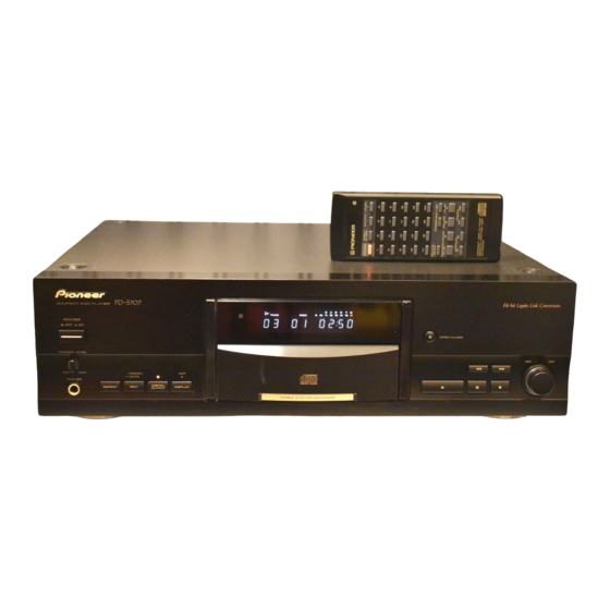
COMPACT DISC PLAYER
PD-S707
THIS MANUAL IS APPLICABLE TO THE FOLLOWING MODEL ( S ) AND TYPE ( S ) .
Model
Type
PD-S707
‡
MY
‡
MV
‡
SD
‡
HPW
CONTENTS
1. SAFETY INFORMATION .................................... 2
2. EXPLODED VIEWS AND PARTS LIST ............. 3
3. SCHEMATIC DIAGRAM ................................... 12
4. PCB CONNECTION DIAGRAM ....................... 19
5. PCB PARTS LIST ............................................. 26
6. ADJUSTMENT .................................................. 30
PIONEER ELECTRONIC CORPORATION
PIONEER ELECTRONICS SERVICE, INC. P.O. Box 1760, Long Beach, CA 90801-1760, U.S.A.
PIONEER ELECTRONIC (EUROPE) N.V. Haven 1087, Keetberglaan 1, 9120 Melsele, Belgium
PIONEER ELECTRONICS ASIACENTRE PTE. LTD. 501 Orchard Road, #10-00 Wheelock Place, Singapore 238880
PIONEER ELECTRONIC CORPORATION 1998
COMPACT DISC PLAYER
POWER
- OFF _ ON
PHONES LEVEL
MIN
MAX
PHONES
Power Requirement
AC220-230V
AC220-230V
AC110V/120-127V/220-230V/240V
AC230- 240V
4-1, Meguro 1-Chome, Meguro-ku, Tokyo 153-8654, Japan
◊Û¿∫≥?≥
Hi-bit Legato Link Conversion
Î
0
OPEN/CLOSE
1
¡
÷ COMPU
OFF
'
÷ ÷ AUTO
DIGITAL
3
8
7
REPEAT
EDIT
DISPLAY
OUTPUT
STABLE PLATTER MECHANISM
The voltage can be converted by the following method.
With the voltage selector
7. GENERAL INFORMATION .............................. 38
7.1 IC ................................................................ 38
7.2 DISPLAY .................................................... 39
7.3 BLOCK DIAGRAM ..................................... 40
................................................................... 41
Î
-
+
OUTPUT LEVEL
1
2
3
4
5
6
7
8
9
10
11
12
13
14
15
16
17
18
19
20
HI-LITE
PROGRAM
> 20
7
8
3
RANDOM
4
¢
1
¡
4
¢
ORDER NO.
'
COMPACT DISC PLAYER
REMOTE CONTROL UNIT
CU-P0092
RRV1981
T-ZZR JULY 1998 Printed in Japan
Advertisement
Table of Contents

Related Manuals for Pioneer PD-S707


Summary of Contents for Pioneer PD-S707
-
Page 1: Table Of Contents
PIONEER ELECTRONICS SERVICE, INC. P.O. Box 1760, Long Beach, CA 90801-1760, U.S.A. PIONEER ELECTRONIC (EUROPE) N.V. Haven 1087, Keetberglaan 1, 9120 Melsele, Belgium PIONEER ELECTRONICS ASIACENTRE PTE. LTD. 501 Orchard Road, #10-00 Wheelock Place, Singapore 238880 PIONEER ELECTRONIC CORPORATION 1998... -
Page 2: Safety Information
PD-S707 1. SAFETY INFORMATION IMPORTANT THIS PIONEER APPARATUS CONTAINS LASER OF CLASS 1. SERVICING OPERATION OF THE APPARATUS S H O U L D B E D O N E B Y A S P E C I A L L Y INSTRUTED PERSON. -
Page 3: Exploded Views And Parts List
See Contrast table(2) Operating Instructions PRE1268 (English/ French/ German/Spanish) Polyethylene Bag See Contrast table(2) (2) CONTRAST TABLE PD-S707/MY, MV, SD and HPW are constructed the same except for the following: Part No. Mark Remarks Symbol and Description MY type MV type... - Page 4 PD-S707 2.2 EXTERIOR (1/2) SD type Only Fuse Holder MV type Only MV and HPW types Only Except MV type Refer to " 2.4 LOADING MECHANISM ASSY TT96". Refer to " 2.3 EXTERIOR (2/2)".
- Page 5 Cord Clamper RNH–184 Voltage Selector See Contrast table(2) Fuse (T5A) See Contrast table(2) (2) CONTRAST TABLE PD-S707/MY, MV, SD and HPW are constructed the same except for the following: Part No. Mark Remarks Symbol and Description MY type MV type...
- Page 6 PD-S707 2.3 EXTERIOR (2/2)
- Page 7 PAN1358 Bonnet Case PYY1257 Screw BBZ40P080FZK NK90FUC Screw PPZ30P080FMC (2) CONTRAST TABLE PD-S707/MY, MV, SD and HPW are constructed the same except for the following: Part No. Mark Remarks Symbol and Description MY type MV type SD type HPW type...
- Page 8 PD-S707 2.4 LOADING MECHANISM ASSY TT96 Refer to " 2.5 SERVO MECHANISM ASSY T96". Spacer...
- Page 9 PD-S707 LOADING MECHANISM ASSY TT96 PARTS LIST Mark No. Description Parts No. Mark No. Description Parts No. Lever Switch (S601) DSK1003 Turn Table PNR1035 Float Screw PBA1027 Servo Mechanism Assy T96 PXA1606 Rubber Belt PEB1186 E Ring YE20FUC Motor Pulley...
- Page 10 PD-S707 2.5 SERVO MECHANISM ASSY T96 SERVO MECHANISM PARTS LIST Mark No. Description Parts No. Carriage D.C. Motor (0.3W) PXM1027 Pinion Gear PNW2055 Spindle Motor Assy PEA1236 (SPINDLE, with Oil) Carriage Base PNW2699 Disc Table PNW1067 Screw JFZ20P030FNI Screw JFZ17P025FZK...
- Page 11 PD-S707...
-
Page 12: Schematic Diagram
PD-S707 3. SCHEMATIC DIAGRAM Note: When ordering service parts, be sure to refer to "EXPLODED VIEWS AND PARTS LIST" or "PCB PARTS LIST". 3.1 OVERALL SCHEMATIC DIAGRAM CN201 LOADING MECHANISM CN403 ASSY TT 96 (PXA1611) KM250NA4L PICK UP ASSY PEA1335... - Page 13 PD-S707 CN404 KP250NA4L POWER BOARD ASSY (PWZ3800: MY) AC Power cord (PWZ3801: MV) PDG1003: MY PRIMARY SWITCH (PWZ3802: SD) AC220-230V 50/60Hz ASSY (PWZ3869:MY PDG1055: MV (PWZ3803: HPW) D20PDY1006G /MV/HPW) AC220-230V 50Hz ADG1123: HPW CN30 (PWZ3870:SD) Power Transformer AC230-240V 50/60Hz 52147-0410...
- Page 14 PD-S707 3.2 MAIN BOARD ASSY, POWER BOARD ASSY and PRIMARY SWITCH ASSY Carbon film Fusible Audio Carbon film MAIN BOARD ASSY (PWZ3793: MY) (PWZ3794: MV) (PWZ3795: SD) (PWZ3796: HPW) –0.7 –0.7 –0.7 to –0.8 10.9 10.9 –11.7 10.9 HPW ONLY...
- Page 15 PD-S707 SIGNAL ROUTE Voltage Measurement : AUDIO SIGNAL ROUTE MODE: PLAY POWER BOARD ASSY (PWZ3800: MY) (PWZ3801: MV) (PWZ3802: SD) (PWZ3803: HPW) –0.1 –0.6 Pin No. Voltage[V] Pin No. Voltage[V] CN501 2.5 2.4 AC POWER CORD J501 PRIMARY SWITCH BOARD ASSY...
- Page 16 PD-S707 3.3 DISPLAY BOARD ASSY, FUNCTION BOARD ASSY and PHONE BOARD ASSY Carbon film PHONE BOARD ASSY Cable holder (PWZ3815: MY, MV) (PWZ3816: HPW, SD) CN30 CN402 DISPLAY BOARD ASSY (PWZ3807: MY, MV, SD) (PWZ3808: HPW) SWITCHES: S701: OPEN/CLOSE S702: PLAY...
- Page 17 PD-S707 MY, MV, SD: Cable holder HPW: CN352 CN351 Cable holder Cable holder HPW ONLY MY, MV, SD : SHORT : OPEN FL HOLDER CN22 Cable holder...
- Page 18 PD-S707 Waveforms ∗1 50T-JUMP: After switching to the pause mode, press the manual search key. Note: The encircled numbers denote measuring point in the schematic diagram. ∗2 FOCUS-IN: Press the play key without loading a disc. IC202- Pin 9 :...
-
Page 19: Pcb Connection Diagram
PD-S707 4. PCB CONNECTION DIAGRAM NOTE FOR PCB DIAGRAMS: 1. Part numbers in PCB diagrams match those in the schematic diagrams. 2. A comparison between the main parts of PCB and schematic Symbol in PCB Symbol in Schematic diagrams is shown below. - Page 20 PD-S707 4.2 MAIN BOARD ASSY SIDE A MAIN BOARD ASSY Q391 CN404 IC341 IC421 Q311 Q312 IC232 VR152 IC202 VR151 VR155 VR154 To Pickup Assy J701(:HPW) J704(:MY/MV/SD) VR156 VR153 Q151 (PNP1449–B) IC201 J702 To Loading Motor and S601 CN610...
- Page 21 PD-S707 SIDE B MAIN BOARD ASSY Q323 IC331 IC401 Q452 Q451 IC303 IC301 IC302 IC151 Q152 (PNP1449–B)
- Page 22 PD-S707 SIDE A 4.3 POWER BOARD and PRIMARY SWITCH ASSEMBLIES CN403 CN11 POWER BOARD ASSY Q421 IC31 IC405 IC21 IC37 IC32 Q403 Q404 J501 CN501 IC35 IC33 IC34 J703 IC36 PRIMARY SWITCH ASSY LIVE NEUTRAL AC POWER CORD (PNP1449–B) Voltage Selector...
- Page 23 PD-S707 SIDE B POWER BOARD ASSY Q405 (PNP1449–B)
- Page 24 PD-S707 SIDE A 4.4 DISPLAY BOARD and FUNCTION BOARD ASSEMBLIES CN22 DISPLAY BOARD ASSY FUNCTION BOARD ASSY IC702 (PNP1449–B) Q752 Q751 SIDE B DISPLAY BOARD ASSY IC701...
- Page 25 PD-S707 SIDE A CN352 CN351 CN351(:HPW) (:MY/MV /SD) Q701 (PNP1449–B) SIDE B FUNCTION BOARD ASSY (PNP1449–B)
-
Page 26: Pcb Parts List
PD-S707 5. PCB PARTS LIST NOTES : ÷ Parts marked by “ NSP ” are generally unavailable because they are not in our Master Spare Parts List. ÷ The mark found on some component parts indicates the importance of the safety factor of the part. - Page 27 PD-S707 MAIN BOARD Assy PWZ3793, PWZ3794, PWZ3795 and PWZ3796 are constructed the same except for the following: Part No. Mark Symbol and Description Remarks PWZ3793 PWZ3794 PWZ3795 PWZ3796 IC331 Not used TC74HC00AF Not used Not used Q323 DTC124EK Not used...
- Page 28 PD-S707 PARTS LIST FOR PD-S707/MY Mark No. Description Parts No. Mark No. Description Parts No. MOTHER BOARD ASSY C413, C414 (220µF/25V) PCH1128 OTHERS RESISTORS PC Board (MOTHER) PNP1449 R427, R428 RD1/4PU273J R163, R164 RD1/4PU470J MAIN BOARD ASSY R420 RFA1/4PL8R2J VR153, VR155 (10KΩ- B) VCP1156 VR151, VR152, VR154 (22KΩ- B)
- Page 29 PD-S707 Mark No. Description Parts No. Mark No. Description Parts No. RESISTORS SWITCHES R39, R40 RDR1/2PM101J S751–S754 VSG1009 R496, R499 RDR1/2PM302J R447, R448 RDR1/2PM471J RESISTORS RDR1/2PM8R2J R756 RD1/4PU181J RFA1/4PL8R2J R755 RD1/4PU221J Other Resistors RS1/10S&&&J RS1/10S103J Other Resistors RD1/4PU&&&J OTHERS OTHERS...
-
Page 30: Adjustment
PD-S707 6. ADJUSTMENT 6.1 PREPARATIONS 6.1.1 Jigs and Measuring Instruments 39 kΩ 0.001µF CD TEST DISC Low pass filter 1 screwdriver screwdriver screwdriver (YEDS-7) (small) (medium) (large) (39 kΩ + 0.001µF) 56 kΩ 0.001µF Dual-trace Precise Ball point hexagon wrench... - Page 31 PD-S707 6.2 ADJUSTMENT 6.2.1 How to Start/Cancel Test Mode TEST MODE : ON TEST MODE TEST MODE W307 W307 W288 W288 Short point Short point MAIN BOARD ASSY MAIN BOARD ASSY Power Switch: ON TEST MODE : PLAY TEST DISC: YEDS-7 ¡...
- Page 32 PD-S707 6.2.3 Check and Adjustment 1. Focus Offset Adjustment Test mode DC voltage VR154 0±50mV None disc MAIN BOARD ASSY Oscilloscope DC Mode V: 5mV/div H: 10mSec/div Player START (CN201) Prove (10:1) MAIN BOARD ASSY 2. Grating Adjustment Turn counterclockwise from null.
- Page 33 PD-S707 3. Tracking Error Barance Adjustment Test mode SPDL servo CLOSE FOCUS servo CLOSE TRKG servo OPEN Innermost TEST DISC circumference VR155 (1 TRK) PLAY MAIN BOARD ASSY Oscilloscope DC Mode V: 10mV/div Player START H: 5mSec/div Low pass filter 1...
- Page 34 PD-S707 5. RF Level Adjustment Test mode SPDL servo CLOSE FOCUS servo CLOSE 1.2VP-P TRKG servo CLOSE ±0.1V Innermost TEST DISC circumference VR153 (1 TRK) PLAY MAIN BOARD ASSY Oscilloscope AC Mode V: 50mV/div H: 10mSec/div Player START (CN201) Prove (10:1) MAIN BOARD ASSY 6.
- Page 35 PD-S707 7. RF Level Adjustment Check Test mode CLOSE SPDL servo FOCUS servo CLOSE TRKG servo CLOSE 1.2VP-P ±0.1V Innermost TEST DISC circumference VR153 (1 TRK) PLAY MAIN BOARD ASSY Make adjustment if the value exceeds the specified range. Oscilloscope...
- Page 36 PD-S707 9. Focus Best Adjustment Test mode SPDL servo CLOSE FOCUS servo CLOSE TRKG servo CLOSE Innermost TEST DISC circumference VR156 (1 TRK) Adjust the RF level to maximum, with PLAY MAIN BOARD ASSY the focus error voltage within ±150mV.
- Page 37 PD-S707 11. Focus Best Adjustment Adjust this point only if adjustment was made in item 10. Test mode SPDL servo CLOSE FOCUS servo CLOSE TRKG servo CLOSE Innermost TEST DISC circumference VR156 (1 TRK) Adjust the RF level to maximum, with PLAY the focus error voltage within ±150mV.
-
Page 38: General Information
PD-S707 7. GENERAL INFORMATION 7.1 IC ¶ The information shown in the list is basic information and may not 7 PE8001A (IC401: MAIN BOARD ASSY) correspond exactly to that shown in the schematic diagrams. 7 D/A CONVERTER IC ¶ Pin Arrangement ¶... -
Page 39: Display
PD-S707 7.2 DISPLAY 7 PEL1094 (V701: DISPLAY BOARD ASSY) 7 FL INDICATOR TUBE ¶ Pin Assignment ¶ Pin Connection ¶ Grid Assignment (10G – 1G) COLOR OF ILLUMINATION ..Orange Other..Green ¶ Anode Connection 10G–3G 10G–3G –– j, p... -
Page 40: Block Diagram
PD-S707 7.3 BLOCK DIAGRAM ÷... -
Page 41: Panel Facilities And Specifications
PD-S707 8. PANEL FACILITIES AND SPECIFICATIONS 7 PANEL FACILITIES Î ◊Û¿∫≥?≥ Hi-bit Legato Link Conversion COMPACT DISC PLAYER – POWER Î — OFF _ ON OUTPUT LEVEL OPEN/CLOSE PHONES LEVEL ¢ ¡ ÷ COMPU ÷ ÷ AUTO PHONES DIGITAL REPEAT...