Table of Contents
Advertisement
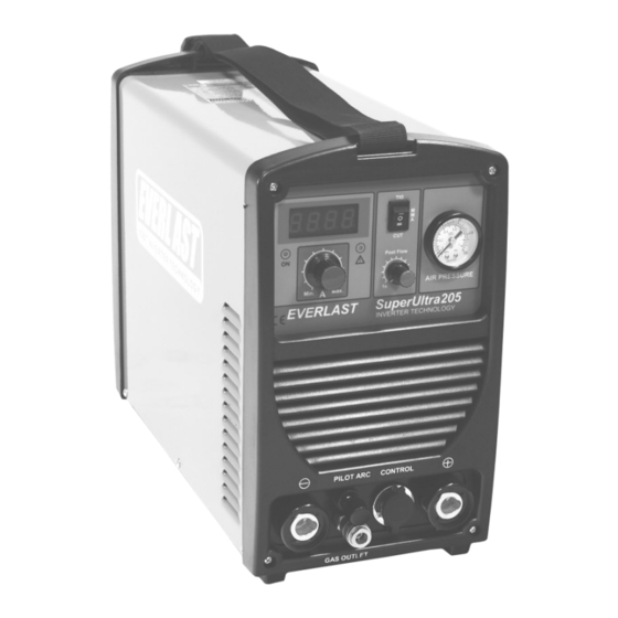
MultiProcess Pulse Tig/Smaw/Plasma Cutter Units
CC
GTAW-P
SMAW
PAC
1
~
PHASE
DC
DC Output SuperUltra Series Units
Safety, Setup and General Use Guide
everlastwelders.com
EVERLAST
SUPERULTRA SERIES
Operator's Manual For
1-877-755-9353
329 Littlefield Ave. South San Francisco, CA 94080 USA
Rev. 1
Specifications and Accessories subject to change without notice.
0 00714-14
Advertisement
Table of Contents
Troubleshooting

Related Manuals for Everlast superultra series


Summary of Contents for Everlast superultra series
- Page 1 EVERLAST SUPERULTRA SERIES MultiProcess Pulse Tig/Smaw/Plasma Cutter Units GTAW-P SMAW PHASE Operator’s Manual For DC Output SuperUltra Series Units Safety, Setup and General Use Guide Rev. 1 0 00714-14 everlastwelders.com Specifications and Accessories subject to change without notice. 1-877-755-9353 329 Littlefield Ave. South San Francisco, CA 94080 USA...
-
Page 2: Table Of Contents
The owner of this product assumes all liability for its use and maintenance. Everlast Power Equipment INC. does not warrant this product or this document for fitness for any particular purpose, for performance/accuracy or for suitability of application. -
Page 3: Letter To The Customer
Your unit registration is important should any information such as product updates or re- calls be issued. It is also important so that we may track your satisfaction with Everlast products and services. If you are unable to register by website, contact Everlast directly through the sales department through the main customer service number in your country. -
Page 4: Everlast Contact Information
Model number: ____________________________ Date of Purchase___________________________ EVERLAST Contact Information Everlast US: Everlast consumer satisfaction email: sales@everlastwelders.com Everlast Website: everlastwelders.com Everlast Technical Support: support@everlastwelders.com Everlast Support Forum: http://www.everlastgenerators.com/forums/index.php Main toll free number: 1-877-755 WELD (9353) 9am—5pm PST M-F 11am-4pm PST Sat. -
Page 5: Safety Precautions
Safe operation and proper maintenance is your responsibility. We have compiled this operator’s manual, to instruct you in basic safety, oper- ation and maintenance of your Everlast product to give you the best possible experience. Much of welding and cutting is based upon experience and com- mon sense. - Page 6 SAFETY PRECAUTIONS These safety precautions are for protection of safety and health. Failure to follow these guidelines may result in serious injury or death. Be careful to read and follow all cautions and warnings. Protect yourself and others. Welding and cutting processes produce high levels of ultraviolet (UV) radiation that can cause severe skin burn and damage.
- Page 7 SAFETY PRECAUTIONS WARNING! Persons with pacemakers should not weld, cut or be in the welding area until they consult with their physician. Some pacemakers are sensitive to EMF radiation and could severely malfunction while welding or while being in the vicinity of someone welding.
- Page 8 SAFETY PRECAUTIONS continued WARNING! Electrical shock can kill. Make sure all electrical equipment is properly grounded. Do not use frayed, cut or otherwise damaged cables and leads. Do not stand, lean or rest on ground clamp. Do not stand in water or damp areas while weld- ing or cutting.
-
Page 9: Introduction And Specifications
AG60 Plasma Torch NOTE: Accessory and consumable style and quantities are subject to change without notice. Consumable starter kits provide only enough consumables to get started. Extra consumables can be purchased through Everlast or almost any local welding supply store. -
Page 10: Unit Specifications
Section 1 Introduction and Specifications DC SUPERULTRA INPUT/OUTPUT SPECIFICATIONS FEATURE/SPEC. SUPERULTRA 205P INVERTER TYPE MOSFET INPUT VOLTAGE ±10%;PHASE/FREQUENCY 110/220V; 1PH/50-60Hz MAXIMUM INPUT AMPS (I₁MAX) 31A @110V/ 27A @ 220V MAXIMUM INPUT RUNNING AMPS (I₁eff) 19A @ 110V/ 17 A @ 220V TIG: [110V] 35%@120A/14.8V 60%@ 93A/13.7V 100%@72A /12.9V [220V] 35%@200A/18V... -
Page 11: General Overview
Section 1 pable of being operated at the max amps for the stated General overview: The SuperUltra 205 from Everlast is percent of time out of 10 minutes without a break to entry level DC TIG, stick and plasma multi-purpose unit, cool down the unit. -
Page 12: Quick Setup Guide, Tig Torch/Cooler Connection
Section 2 QUICK SETUP AND USE GUIDE QUICK SETUP GUIDE: TIG CONNECTIONS TORCH (-) WORK (+) PILOT ARC CONTROL GAS (Ar) AIR-COOLED TORCH CONTROL 26 SERIES CONTROL FOOT PEDAL NOTE: Torch switch and foot pedal control cannot be used at the same. -
Page 13: Quick Setup Guide, Plasma Connection
Section 2 QUICK SETUP AND USE GUIDE QUICK SETUP GUIDE: PLASMA CONNECTIONS WORK (+) PILOT ARC CONTROL PILOT SWITCH AG-60 NOTES: Do not attempt to use the foot pedal to control the amps. Do not flip the process switch while cutting or unit failure may result. Attempt to cut only when air pressure is beins supplied. -
Page 14: Quick Setup Guide, Stick Polarity And Connection
Section 2 QUICK SETUP AND USE GUIDE QUICK SETUP GUIDE: STICK POLARITY AND CONNECTIONS PILOT ARC CONTROL TORCH (+) WORK (-) -
Page 15: Quick Setup Guide, Rear Connection For Plasma
Section 2 QUICK SETUP AND USE GUIDE QUICK SETUP GUIDE: REAR CONNECTIONS FOR PLASMA OPERATION Compressor and Dryer Diagram Compressor and Air hose w fittings (Customer Supplied) Regulator Assembly with built-in water trap and dirt filter (Included) 1/4” Automotive Universal style quick connector (Included) CLAMP Air Dryer/Oil Filter... -
Page 16: Quick Setup Guide, Rear Connection For Tig
T configuration of two ball valves or a Y valve( both customer supplied) to switch between the plasma air EVERLAST input and TIG shielding gas as needed without NOTE: Use Ar or Ar/He only. Do not... -
Page 17: Front Panel Features And Controls
Section 2 QUICK SETUP AND USE GUIDE FRONT PANEL FEATURES AND CONTROLS 10. TIG/CUT/STICK SWITCH 1. AMP DISPLAY 9. AIR PRESSURE 2. ON/TEMP/O.C 3. AMP CONTROL 4. POST FLOW TIME 5. PILOT ARC PILOT ARC CONTROL 8. POSITIVE (25 OR 35 SERIES) 6. - Page 18 (10-15 minutes). Cycle the power switch to reset the machine only after the machine has had time to cool. The duty cycle and overcurrent warning lights should go off after cycling the power switch on the machine. If it does not, and will not weld, contact Everlast. 3. Amp Control Controls amperage output.
-
Page 19: Rear Panel Features And Controls
You may then either create an 240V to 120V pigtail adapter for 120V operation, or purchase one directly from Everlast for use on 120V. For use with 120V input only, remember output will be reduced. Be sure to maintain polarity when wiring for 120V use, with white as the neutral, and green as the ground. - Page 20 5% is preferred. Operating the unit on square wave output or modified sine wave generator is strictly prohibited. Contact the manufacturer of the genera- tor for this information. Everlast does not have an “approved” list of generators. But, if the generator is not listed as clean power by its manufacturer, then operation is prohibited.
-
Page 21: Tungsten Preparation
Section 3 Basic theory and function TUNGSTEN PREPARATION 1. Use a dedicated grinding wheel or contamination may re- sult. Do not breath grinding dust! Wear eye protection and gloves. 2. Hold Tungsten firmly. 3. Grind perpendicular to grind- ing wheel face. Allow tungsten to grind away slowly, creating point. -
Page 22: High Frequency Start Tig Operation
Section 3 Basic theory and function HIGH FREQUENCY START TIG OPERATION <1/8 <1/8” 1. Position the point of the sharpened tungsten about 1/8” or less above the metal. 2. Press the torch trigger or press the foot pedal to initiate the arc. The HF arc will be initiated. It may appear briefly as a blue spark. 3. -
Page 23: Stick Arc Starting Procedure
Section 3 Basic theory and function STICK OPERATION STARTING METHODS Tapping Method Scratch/Match Method 1. Turn on the power switch on the rear of the unit. Allow unit to cycle through its start up program. 2. Select the Stick mode with the HF/Lift Start/Stick selector switch. 3. -
Page 24: Plasma Function And Operation
Section 3 Basic theory and function Helpful Hint: If difficulty is observed in starting the arc, it may be time to readjust the point gap setting found inside. The HF points tend to wear and get dirty over time. This is a normal maintenance item and not something for warranty consideration. Proper point gap adjustment is .035 “to .045”. - Page 25 Section 3 Basic theory and function Helpful Hint: If difficulty is observed in starting the arc, it may be time to readjust the point gap setting found inside. The HF points tend to wear and get dirty over time. This is a normal maintenance item and not something for warranty consideration. Proper point gap adjustment is .035 “vto .045”.
- Page 26 Section 3 Basic theory and function RESULTS OF CUT AT CORRECT SPEED, RESULTS OF CUT AT FAST SPEED AIR PRESSURE AND TORCH ANGLE ROUGH, DISTINCT CUT LINES SPACED FAR APART SMOOTH, EVEN CUT LINES WITH A S REARWARD SWEEP MINIMAL EASY TO CLEAN DROSS NOTICEABLE SMALL, HARD DROSS RESULTS OF TOO MUCH CURRENT OR RESULTS OF CUT AT SLOW SPEED...
- Page 27 Section 3 Basic theory and function Helpful Hint: If difficulty is observed in starting the arc, it may be time to readjust the point gap setting found inside. The HF points tend to wear and get dirty over time. This is a normal maintenance item and not something for warranty consideration. Proper point gap adjustment is .035 “vto .045”.
-
Page 28: Recommendations For Polarity/Amps/Tungsten
Section 3 Basic theory and function GENERAL POLARITY RECOMMENDATIONS* *Follow manufacturer of stick electrode for complete polarity recommendations PROCESS TORCH POLARITY WORK POLARITY TIG (GTAW) STICK (SMAW) TIG (GTAW) OPERATION GUIDE FOR STEEL (ALUMINUM)* *As a general rule, set amperage using 1 amp for every .001” of metal thickness for aluminum. Less is required for DC. METAL THICKNESS WELDING AMPS TUNGSTEN DIA. -
Page 29: Expanded View Of Tig Torch
Section 3 Basic theory and function EXPANDED VIEW OF TIG TORCH (Actual appearance may vary slightly from what is listed.) 5/8” Parts for Standard 26 Series Torch ( 18 series uses same consuma- QTY. bles and basic design is similar, except water cooler line plumbing) Long Back Cap with O-Ring Short Back Cap Opt. -
Page 30: Expanded View Of Ag60 Plasma Torch
Section 3 Basic theory and function AG60/SG 55 PLASMA TORCH ITEM DESCRIPTION PART NUMBER/SKU Torch Head/Body E-WSD-061 Electrode 1.0mm E-AG60-TIP Tip/Nozzle E-AG60-EL Shielding Cup E-AG60-CUP... -
Page 31: Pin Connector Pin-Out
Section 3 Basic theory and function 7 PIN CONNECTOR FOR FOOT PEDAL Bridge to 7 To Pedal or Torch Switch Bridge to 6 To Pedal or Torch Switch... -
Page 32: Troubleshooting
Check gas flow. Adjust for higher flow of gas. Listen for audible click of gas solenoid. If no click is heard, then contact Everlast Support. Clean weld properly, especially in Aluminum. Too short of post flow. Check tungsten stick out. -
Page 33: Trouble Shooting
Make sure swirl ring is not cracked. Arc will try to start if touched to the metal, but no air Stuck or dirty solenoid valve. Contact Everlast. Wrong Pro- flow while switch is pressed. cess selected.
Need help?
Do you have a question about the superultra series and is the answer not in the manual?
Questions and answers