
Related Manuals for National Instruments NI 9212


Summary of Contents for National Instruments NI 9212
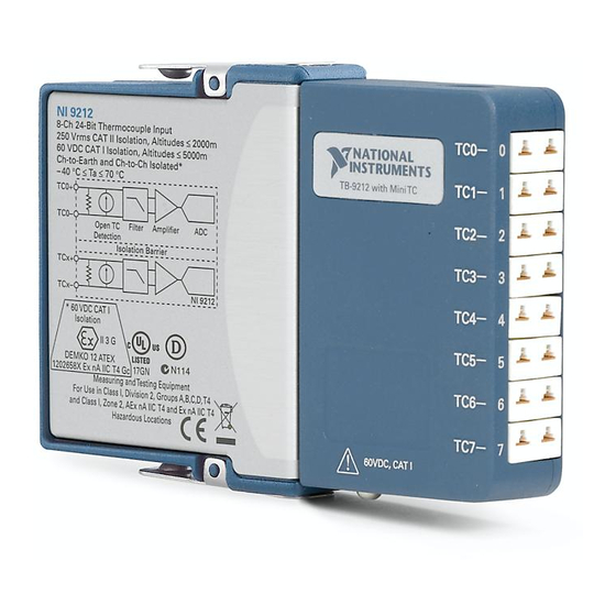
- Page 1 GETTING STARTED GUIDE NI 9212 and TB-9212 8 TC, ±78 mV, 24 Bit, 95 S/s/ch Simultaneous, Isothermal Terminal Block...
-
Page 2: Safety Guidelines
This document explains how to connect to the NI 9212 using the TB-9212. Before you begin, complete the software and Note hardware installation procedures in your chassis documentation. The guidelines in this document are specific to Note the NI 9212. The other components in the system might not meet the same safety ratings. -
Page 3: Safety Guidelines For Hazardous Voltages
You must use the TB-9212 included with the NI 9212 to ensure that the terminals are not accessible. NI 9212 Getting Started Guide | © National Instruments | 3... -
Page 4: Safety Voltages
Withstand 1,500 Vrms, verified by a 5 s dielectric test Up to 5,000 m altitude Continuous 60 VDC, Measurement Category I Withstand 1,000 Vrms, verified by a 5 s dielectric test 4 | ni.com | NI 9212 Getting Started Guide... - Page 5 Such voltage measurements include signal levels, special equipment, limited-energy parts of equipment, circuits powered by regulated low-voltage sources, and electronics. NI 9212 Getting Started Guide | © National Instruments | 5...
-
Page 6: Safety Guidelines For Hazardous Locations
Categories III or IV. Safety Guidelines for Hazardous Locations The NI 9212 is suitable for use in Class I, Division 2, Groups A, B, C, D, T4 hazardous locations; Class I, Zone 2, AEx nA IIC T4 6 | ni.com | NI 9212 Getting Started Guide... - Page 7 IP54 as defined by IEC/EN 60079-15. For Division 2 and Zone 2 applications, Caution connected signals must be within the following limits. Capacitance 0.2 µF maximum NI 9212 Getting Started Guide | © National Instruments | 7...
- Page 8 Zone 2 hazardous locations, in ambient temperatures of -40 °C ≤ Ta ≤ 70 °C. If you are using the NI 9212 in Gas Group IIC hazardous locations, you must use the device in an NI chassis that has been evaluated as Ex nC IIC T4, Ex IIC T4, Ex nA IIC T4, or Ex nL IIC T4 equipment.
-
Page 9: Electromagnetic Compatibility Guidelines
Furthermore, any changes or modifications to the product not expressly approved by National Instruments could void your authority to operate it under your local regulatory rules. NI 9212 Getting Started Guide | © National Instruments | 9... -
Page 10: Special Conditions For Marine Applications
In addition, take precautions when designing, selecting, and installing measurement probes and cables to ensure that the desired EMC performance is attained. 10 | ni.com | NI 9212 Getting Started Guide... -
Page 11: Preparing The Environment
Preparing the Environment Ensure that the environment in which you are using the NI 9212 meets the following specifications. Operating temperature -40 °C to 70 °C (IEC 60068-2-1, IEC 60068-2-2) Operating humidity 10% RH to 90% RH, (IEC 60068-2-78) noncondensing... - Page 12 TB-9212 Pinout TC4+ TC0+ TC4- TC0- TC5+ TC1+ TC5- TC1- TC6+ TC2+ TC6- TC2- TC7+ TC3+ TC7- TC3- 12 | ni.com | NI 9212 Getting Started Guide...
-
Page 13: Thermocouple Connections
Table 1. Signal Descriptions Signal Description Positive thermocouple connection Negative thermocouple connection Thermocouple Connections Shield Thermocouple Ground TB-9212 NI 9212 NI 9212 Getting Started Guide | © National Instruments | 13... - Page 14 NI 9212 Connection Guidelines • Make sure that devices you connect to the NI 9212 are compatible with the module specifications. • The shield grounding methodology can vary depending on the application. • Refer to your thermocouple documentation or the thermocouple wire spool to determine which wire is the positive lead and which wire is the negative lead.
- Page 15 (30 AWG to 20 AWG) wire with 5.1 mm (0.2 in.) of the inner insulation stripped and 51 mm (2.0 in.) of the outer insulation stripped • Zip tie • Screwdriver NI 9212 Getting Started Guide | © National Instruments | 15...
- Page 16 What to Do 16 | ni.com | NI 9212 Getting Started Guide...
- Page 17 4. Replace the foam pad in the TB-9212 opening, reinstall the top cover, and tighten the captive screws. NI 9212 Getting Started Guide | © National Instruments | 17...
-
Page 18: Where To Go Next
NI 9212 Datasheet NI 9212 Datasheet NI-RIO Help NI-DAQmx Help LabVIEW FPGA Help LabVIEW Help RELATED INFORMATION C Series Documentation Services & Resources ni.com/services ni.com/info cseriesdoc Located at ni.com/manuals Installs with the software 18 | ni.com | NI 9212 Getting Started Guide... -
Page 19: Worldwide Support And Services
You can obtain the DoC for your product by visiting ni.com/certification. If your product supports calibration, you can obtain the calibration certificate for your product at ni.com/calibration. NI 9212 Getting Started Guide | © National Instruments | 19... - Page 20 U.S. Government Customers: The data contained in this manual was developed at private expense and is subject to the applicable limited rights and restricted data rights as set forth in FAR 52.227-14, DFAR 252.227-7014, and DFAR 252.227-7015. © 2015—2016 National Instruments. All rights reserved. 374358B-01 Apr16...
Need help?
Do you have a question about the NI 9212 and is the answer not in the manual?
Questions and answers