Table of Contents
Advertisement
Quick Links
Advertisement
Table of Contents

Related Manuals for Iseki TG5330


Summary of Contents for Iseki TG5330
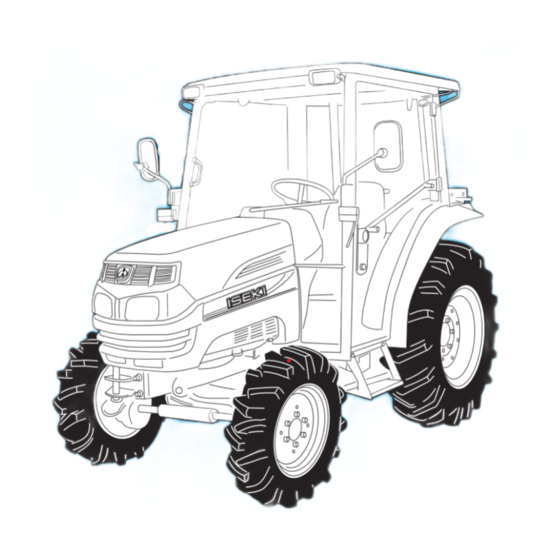
- Page 1 I S E K I T R A C T O R S MODELS: TG5330 TG5390 TG5470...
-
Page 2: To Our Customer
ISEKI TRACTORS TO OUR CUSTOMER Thank you very much for purchasing an ISEKI tractor. This operator s manual provides the information necessary for operating and maintaining your tractor safely and properly. The contents are mainly composed of the following two... -
Page 3: Table Of Contents
TG5330,5390,5470 TABLE OF CONTENTS TO OUR CUSTOMER ..........ENGINE SPEED CONTROLS........32 TABLE OF CONTENTS ..........TRANSMISSION SHIFT LEVERS......32 Forward/Reverse Manual Shuttle Lever.... 33 1. SAFETY ..............Range And Gear Shift Levers......33 PERSONAL SAFETY INSTRUCTIONS ....DIFFERENTIAL LOCK PEDAL......... 34 MAKING YOUR TRACTOR A SAFE VEHICLE.. - Page 4 Detaching Implements......... 73 WASHER RESERVOIR..........108 JOYSTICK OPERATION (ACCESSORY) ....74 HEATER OPERATION (TG5330/5390)....109 EXTERNAL AUXILIARY HYDRAULICS FRESH AIR VENT LEVER(TG5330/5390)....109 (Except Center ROPS type: accessory, TEMPERATURE ADJUSTMENT LEVER Center ROPS type: 1-spool as standard, 2-spools as (TG5330/5390) ............110 accessory) ..............
- Page 5 TG5330,5390,5470 When there is moist dirt or oil ......131 TREAD WIDTH SETTING ........160 FUEL SYSTEM............133 Fuel Filter............. 133 11. GENERAL DIMENSIONS Air-Bleeding Fuel System ........134 REAR ROPS TYPE ..........161 Fuel Tank Filler Cap ..........134 CENTER ROPS TYPE..........
-
Page 6: Safety
SAFETY SAFETY PERSONAL SAFETY INSTRUCTIONS Whenever you see the words and symbols below, used in this Operator‘s Instruction Book and on decals, you MUST take note of their instructions as they relate to personal safety. DANGER: This symbol together with the word DANGER indicates an imminently haz- ardous situation that, if not avoided, will result in DEATH OR VERY SERIOUS INJURY. -
Page 7: How To Be A Safe Operator
TG5330,5390,5470 mind that the implement is wider and may roll easily. If the implement can be folded, fold it beforehand. If there are road or railway crossings where the visibility is poor, you should install on the machine a mirror to give a view ahead of you so that you need not move your machine too far into the intersection. -
Page 8: Before Operation
If safety devices are damaged or do no work, please consult your ISEKI dealer. FIG. 1-6 (3) Before removing a safety devices, such as a safety cover, be sure that the machine has stopped com- pletely. -
Page 9: When Travelling
TG5330,5390,5470 WHEN TRAVELLING (1) When you travel on roads, ensure the differential lock is off, or the tractor may turn over. (2) Do not make sharp turns when operating at high speed or for transportation as the tractor may turn over. -
Page 10: Loading Onto Or Unloading Froma Truck
(7) Use ramps with the same or better specifications mentioned below. When the machine is equipped with attachments other than those included in the specifications mentioned below, ask your ISEKI deal- er for advice. -
Page 11: Specifications Of The Ramps
(5) If you use a trailer, use a proper one which suits your tractor. Using an improper trailer may cause serious accidents. Never attempt to haul beyond the tractor‘s capacity. If you have a question, please consult ISEKI dealer. (6) When moving the machine toward an implement for the purpose if installing the implement, never allow any one to stand in between. -
Page 12: Inspection And Maintenance
SAFETY INSPECTION AND MAINTENANCE (1) When servicing the tractor or mounting or dismount- ing an implement, place the tractor on level, hard ground which is sufficiently illuminated, or unexpected accidents may occur. (2) When servicing the tractor, follow the instructions list- ed below: ・... -
Page 13: Storage
Do not attempt to service a tire unless you have the proper equipment and experience to perform the job. Have the work carried out by your ISEKI dealer or a qualified repair service. When seating tire beads onto rims, never exceed the maximum inflation specifications specified on the tire. -
Page 14: Maintenance Of The Electric System
SAFETY MAINTENANCE OF THE ELECTRIC SYSTEM TO MAINTENACE ELECTRIC WIRING (1) When servicing the electric wiring, stop the engine without fail. Otherwise your hands or clothes may be caught in or sandwiched between rotating parts. (2) Before manipulating electric parts, be sure to discon- nect the earth battery cable (-), or you may get an electric shock or be injured by sparks. -
Page 15: To Handle Booster Cables
TG5330,5390,5470 When disconnecting the battery cables, disconnect the earth cable (-) first without fail. When connecting the bat- tery cables, connect the positive cable (+) first. Disconnecting or connecting in wrong order may lead to a short circuit or sparks. -
Page 16: Safety Decals And Their Locations
SAFETY SAFETY DECALS AND THEIR LOCATIONS (5) Ether label (Code No.1674-904-002-1) (1) Fan warning label (Code No. 1705-902-006-0) WARNING: RISK OF EXPLOSION WARNING: RISK OF ENTANGLEMENT Ether or other starting fluid should never be used to Stay clear of the fan while it is running. start engines equipped with glow plugs. - Page 17 TG5330,5390,5470 (8) Radiator label Take care of handling the battery. (Code No.1705-902-008-0) Improper handling may lead to explosion. Never short the poles. Charge the battery in a well ventilated place. (10) Starter warning label (Code No.1705-902-007-0) WARNING: HIGH PRESSURE STEAM AND HOT...
- Page 18 SAFETY (12) Fuel label (15) Starting engine caution label (Code No.1705-904-001-0) (Code No.1640-904-005-1) (Except for HST type) DANGER: RISK OF EXPLOSION AND BURNS Use only diesel fuel. Before replenishing fuel, be sure to stop the engine and wait until the engine and heated parts cool down sufficiently.
-
Page 19: Location Of Safety Decals
TG5330,5390,5470 LOCATION OF SAFETY DECALS Location of all instruction decals provided as a reference. Replace any decals that are damaged, missing or are not readable. Consult your dealer. -
Page 20: (Only Cabin Type)
SAFETY (ONLY CABIN TYPE) Location of all instruction decals provided as a reference. Replace any decals that are damaged, missing or are not readable. Consult your dealer. -
Page 21: Introduction
Tractors. Every effort has been made to provide correct and concise information to you, the operator, as available at date of book publication. Your ISEKI Dealer is available should items in this book or details of your machine not be understood. -
Page 22: Tractor Identification
TRACTOR IDENTIFICATION TRACTOR IDENTIFICATION MODEL/SERIAL NUMBER Each Tractor is identified by means of Tractor model and serial numbers. As a further identification, engine and chassis are provided with identification numbers. To ensure prompt, efficient service when ordering parts or requesting repairs from authorized Dealer, record these numbers in spaces provided. -
Page 23: Engine Model Number
TG5330,5390,5470 ENGINE MODEL NUMBER ENGINE SERIAL NUMBER FIG. 3-3: Engine model number, 1, is cast on right side of engine block, below the injection pump. Engine serial number, 2, is stamped into cylinder block, below engine model number. FIG. 3-3 CHASSIS NUMBER FIG. -
Page 24: Rops Type
TRACTOR IDENTIFCATION Rear ROPS type FIG. 3-5 FIG. 3-5: Identification and terminology of major components, as given in this book, are as follows: Front Wheels Front Hitch Fuel Tank Filler Engine Check Chain Foot Step Lift Rod Transmission Lower Link Front Wheel-Drive Shaft Rear Wheels Headlight... -
Page 25: Center Rops Type
TG5330,5390,5470 CENTER ROPS type FIG. 3-6 FIG. 3-6: Identification and terminology of major components, as given in this manual, are as follows: Front Wheels Front Bumper Fuel Tank Filler Engine Check Chain Foot Step Lift Rod Transmission Lower Link Front Wheel-Drive Shaft... -
Page 26: Cabin Type
TRACTOR IDENTIFCATION CABIN type COBO ITALY TOP TOP HALOGEN HALOGEN KNIGHT BEAM BL84−290 KNIGHT BEAM BL84−290 FIG. 3-7 FIG. 3-7: Identification and terminology of major components, as given in this book, are as follows: Front Wheels Front Hitch Fuel Tank Filler Engine Check Chain Foot Step Lift Rod Transmission... -
Page 27: Instruments & Controls Standard Type
TG5330,5390,5470 INSTRUMENTS & CONTROLS - STANDARD TYPE - FIG. 4-1 FIG. 4-1: General layout and location of controls within operator’s area on Tractor. Specific use of these controls is given later in this section and also in Operation section of this book:... -
Page 28: Instrument Panel
INSTRUMENTS & CONTROLS INSTRUMENT PANEL FIG. 4-2: Arrangement of gauges. Control switches and indicators located in instrument panel. Items are detailed in the descriptions that follow: Electric Fuel Shut-Off Turning main switch to off position will stop engine. FIG. 4-2 Main Switch FIG. -
Page 29: Indicator Light Strip
TG5330,5390,5470 Indicator Light Strip FIG. 4-5: Indicator light strip, 2, contains several warning lights to monitor certain functions. Currently used posi- tions (from left to right) are: ・ l Main (High) Beam - Illuminates when headlamps in front grille are selected to high beam position bylight switch. -
Page 30: Fuel Gauge
INSTRUMENTS & CONTROLS Fuel Gauge FIG. 4-8: Gauge, 5, indicates level of diesel fuel in fuel tank when main switch is ON NOTE: Use only clean diesel fuel and clean area to pre vent dirt/water entry into fuel tank when refilling.DO NOT run out of fuel as bleeding air from the system will be required. -
Page 31: Power Take-Off (Pto) Switch
TG5330,5390,5470 FIG. 4-11: Turn/hazard indicator lights, 11 and 12, will operate with ROPS-mounted warning lights. This provides operator with easy indication of warning light selection. FIG. 4-11 Power Take-Off (PTO) Switch FIG. 4-12 & 4-13: A dial-type safety switch, 1, is used to engage and disengage the PTO drive system. -
Page 32: Main Clutch Pedal
INSTRUMENTS & CONTROLS MAIN CLUTCH PEDAL FIG. 4-14: Foot pedal, 1, disengages engine from trans- mission when fully depressed, to permit engine starting, selecting/changing gears and stopping Tractor movement. Four-wheel drive selection also requires clutch disengage- ment. Slowly raising the pedal will engage clutch and start Tractor moving in selected gear. -
Page 33: Engine Speed Controls
TG5330,5390,5470 ENGINE SPEED CONTROLS CAUTION: Always select engine speed to ensure safe operation. Reduce speed prior to turning or backing Tractor. IMPORTANT: DO NOT race or excessively load cold engine. FIG. 4-17: Hand Throttle Lever, 1 - Controls engine speed and will remain in position selected by the operator. -
Page 34: Forward/Reverse Manual Shuttle Lever
INSTRUMENTS & CONTROLS Forward/Reverse Manual Shuttle Lever FIG. 4-18: Forward or reverse travel is selected by lever, 1, on steering column. Moving lever forward will select for- ward travel, lever rearward will select reverse travel. A center neutral position should be selected whenever Tractor is stopped. -
Page 35: Differential Lock Pedal
TG5330,5390,5470 DIFFERENTIAL LOCK PEDAL FIG. 4-21: When differential lock pedal, 1, is depressed, both rear axles are locked together to provide equal trac- tion to both rear wheels. This is especially important when operating in loose soil or slippery conditions. -
Page 36: Mid Pto Selector Lever (Accessory)
INSTRUMENTS & CONTROLS MID PTO SELECTOR LEVER (accessory) FIG. 4-24: The mid PTO selector lever, 1, controls the mid PTO on the tractor. When the lever is shifted rearward, the mid PTO operates at 1916 rpm (when engine speed is 2600 rpm). When lever is returned, neutral is selected, and the mid PTO will stop rotating. -
Page 37: Three-Point Hitch
TG5330,5390,5470 THREE-POINT HITCH Complete operating instructions for three-point hitch are given in Operation section of this book. Control Lever FIG. 4-25: Position control lever, 1, adjusts height of three-point hitch on rear of Tractor. Setting lever in a par- ticular position will set the height respectively. Full up position is with lever fully rearward and full down position is with lever completely forward. -
Page 38: Joystick Control Lever (Accessory)
INSTRUMENTS & CONTROLS JOYSTICK CONTROL LEVER (accessory) Fig.4-27:The Joystick control lever, 1, can be used to determine the front loader boom position and bucket posi- tion. The lever is located to the front on the right side of the seat. The "Raise", "Lower", "Free Flow"... -
Page 39: Comfort Adjustments
TG5330,5390,5470 COMFORT ADJUSTMENTS Steering Column Tilt FIG. 4-29: Steering column can be adjusted forward and rearward to any one of three positions, enabling operator to select best steering wheel position. While holding steering wheel with both hands, depress tilt locking pedal, 1, and select desired position. Release pedal and make sure column is securely locked by pedal returning to original position. -
Page 40: Power Shift Type & Hst Type
INSTRUMENTS & CONTROLS INSTRUMENTS & CONTROLS - POWER SHIFT TYPE & HST TYPE- Power Shift type FIG. 4-31a FIG. 4-31a: General layout and location of controls within operator’s area on Tractor. Specific use of these controls is given later in this section and also in Operation section of this book: Steering Wheel Foot Throttle Pedal Forward / Reverse Lever... -
Page 41: Hst Type
TG5330,5390,5470 HST type FIG. 4-31b FIG. 4-31b: General layout and location of controls within operator’s area on Tractor. Specific use of these controls is given later in this section and also in "Operation" section of this book: Steering Wheel Three Point Hitch Position Control Lever... -
Page 42: Instrument Panel
INSTRUMENTS & CONTROLS INSTRUMENT PANEL FIG. 4-32: Arrangement of gauges. Control switches and indicators located in instrument panel. Items are detailed in the descriptions that follow: Electric Fuel Shut-Off Turning main switch to off position will stop engine. FIG. 4-32 Main Switch FIG. -
Page 43: Indicator Light Strip
TG5330,5390,5470 Indicator Light Strip FIG. 4-35: Indicator light strip, 3, contains several warning lights to monitor certain functions. Currently used posi- tions (from left to right) are: ・ l Main (High) Beam - Illuminates when headlamps in front grille are selected to high beam position bylight switch. -
Page 44: Coolant Temperature Gauge
INSTRUMENTS & CONTROLS Coolant Temperature Gauge FIG. 4-36: Gauge, 4, indicates engine coolant tempera- ture when main switch is selected to ON ・ - Shows too cool temperature for severe work. Allow to warm before applying heavy load. ・ - Indicates overheating Reduce engine speed to idle, allow to run at no load several minutes and investigate cause (refer to Troubleshooting ). -
Page 45: Fuel Gauge
TG5330,5390,5470 Fuel Gauge FIG. 4-39: Scale, 7, indicates level of diesel fuel in fuel tank when main switch is ON NOTE: Use only clean diesel fuel and clean area to pre vent dirt/water entry into fuel tank when refilling.DO NOT run out of fuel as bleeding air from the system will be required. -
Page 46: Power Take-Off (Pto) Switch
INSTRUMENTS & CONTROLS FIG. 4-42: Turn/hazard indicator lights, 13 and 14, will operate with ROPS-mounted warning lights. This provides operator with easy indication of warning light selection. FIG. 4-42 Power Take-Off (PTO) Switch FIG. 4-43 & 4-44: A dial-type safety switch, 1, is used to engage and disengage the PTO drive system. -
Page 47: Main Clutch Pedal (Only Power Shift Type)
TG5330,5390,5470 MAIN CLUTCH PEDAL (ONLY POWER SHIFT TYPE) FIG. 4-45: Foot pedal, 1, disengages engine from transmis- sion when fully depressed, to permit engine starting, select- ing/changing gears and stopping Tractor movement. Four- wheel drive selection also requires clutch disengagement. -
Page 48: Engine Speed Controls
INSTRUMENTS & CONTROLS ENGINE SPEED CONTROLS CAUTION: Always select engine speed to ensure safe operation. Reduce speed prior to turning or backing Tractor. IMPORTANT: DO NOT race or excessively load cold engine. FIG. 4-49: Hand Throttle Lever, 1 - Controls engine speed and will remain in position selected by the operator. -
Page 49: Forward/Reverse Power Shuttle Lever
TG5330,5390,5470 Forward/Reverse Power Shuttle Lever FIG. 4-50: With power shuttle lever,1, forward or reverse direction changes are possible without depressing the main clutch pedal. Lift up and move lever forward tp shift to the forward travel position, move lever rearward to shift to the reverse travel position. -
Page 50: Transmission Shift Lever And Controls (Hst Type)
INSTRUMENTS & CONTROLS TRANSMISSION SHIFT LEVER AND CONTROLS (HST type) One shift lever is used to select a range of ground travel speed through different gear reductions within the drive train. A hydrostatic control unit (using a control pedal) allows infinitely variable speeds, from zero to top speed, in each range. -
Page 51: Differential Lock Pedal
TG5330,5390,5470 DIFFERENTIAL LOCK PEDAL Power shift type FIG. 4-54a,54b: When differential lock pedal, 1, is depressed, both rear axles are locked together to provide equal traction to both rear wheels. This is especially important when operating in loose soil or slippery condi- tions. -
Page 52: Rear Pto Selector Lever
INSTRUMENTS & CONTROLS REAR PTO SELECTOR LEVER FIG. 4-57: Rear PTO (power takeoff) selector lever, 1, controls rear PTO on Tractor. When lever is forward, 540 rpm rear PTO is selected. When lever is rearward, 1000 rpm rear PTO is selected. When lever is returned to rear neutral (N) position, the gear drive is disengaged. -
Page 53: Three-Point Hitch
TG5330,5390,5470 THREE-POINT HITCH Complete operating instructions for three-point hitch are given in Operation section of this book. Control Lever FIG. 4-59: Position control lever, 1, adjusts height of three-point hitch on rear of Tractor. Setting lever in a par- ticular position will set the height respectively. Full up position is with lever fully rearward and full down position is with lever completely forward. -
Page 54: Joystick Control Lever (Accessory)
INSTRUMENTS & CONTROLS JOYSTICK CONTROL LEVER (accessory) Fig.4-61:The Joystick control lever, 1, can be used to determine the front loader boom position and bucket posi- tion. The lever is located to the front on the right side of the seat. The "Raise", "Lower", "Free Flow"... -
Page 55: Comfort Adjustments
TG5330,5390,5470 COMFORT ADJUSTMENTS Steering Column Tilt FIG. 4-63: Steering column can be adjusted forward and rearward to any one of three positions, enabling operator to select best steering wheel position. While holding steering wheel with both hands, depress tilt locking pedal, 1, and select desired position. Release pedal and make sure column is securely locked by pedal returning to original position. -
Page 56: Operation Standard Type
OPERATION OPERATION - STANDARD TYPE - BREAK-IN PERIOD STARTING Pre-Start Inspection Operation of Tractor within the first fifty hours can be a major factor in determining the performance and life of the Prior to daily start-up of Tractor, a few basic procedures engine and Tractor: should be followed to ensure Tractor is in operating order to insure life and dependability:... -
Page 57: Normal Starting
TG5330,5390,5470 Normal Starting CAUTION: Do not attempt to start the tractor unless seated in the operator’s seat. Do not allow anyone on the tractor except for the operator. FIGS. 5-1 & 5-2: To start the engine, proceed as follows: 1. Apply parking brake ,1. -
Page 58: Restarting Warm Engine
OPERATION Restarting Warm Engine Warm Up Period When restarting an engine that is still warm from previous After starting a cold engine, let engine idle at slow speed use, the same procedure is used as with Normal Starting to make sure all engine components are lubricated. except step no. -
Page 59: Operator Observations
TG5330,5390,5470 Operator Observations Starting Circuit Operation Constant attention should be paid to the following points Tractor is equipped with a starting system to protect the during operation: operator. To permit tractor to be started (start motor to operate), ALL the following is required: ・... -
Page 60: Ground Speed Selection
OPERATION GROUND SPEED SELECTION Tractor is equipped to provide twelve forward gear speeds and twelve reverse gear speeds. FIG. 5-4: Gear shift lever, 1, provides four gear selections. These gear selections are compounded by range shift lever, 2. The range shift lever provides three major changes in ground speed. - Page 61 Range Gear right. Engine Speed 2600rpm Forward NOTE: Ground speed indicated at 2600 engine rpm with TG5330 - 12.4 - 24, TG5390 - 13.6 - 24 TG5470 - 13.6 - 28 agriculturaltype rear tires . 11.7 12.2 11.4 17.1 17.9 16.7...
-
Page 62: Stopping Tractor
OPERATION STOPPING TRACTOR FIG. 5-8: Brake pedals, 1 and 2, may be used independ- ently to operate respective brake and assist turning at low speed operation. Unlatch brake pedals and use as required to assist turning. When Tractor is being used at higher rate of speed, brake pedals must be latched together with interlocking plate, 3, so both brakes will apply at the same time. -
Page 63: Differential Lock
TG5330,5390,5470 DIFFERENTIAL LOCK FIG. 5-10: Differential lock pedal, 1, should only be depressed when required as steering ability is greatly reduced. To engage differential lock, depress clutch pedal and allow all rear wheel movement to stop. Depress lock pedal and slowly engage the clutch. -
Page 64: Power Take-Off (Pto)
OPERATION POWER TAKE-OFF (PTO) Ensure that all PTO safety shields are in place at all times. WARNING: PTO shafts and PTO driven imple- ments can be extremely dangerous. Observe Ensure all PTO-driven implements are in the following important points: good condition and conform to current stan- dards. -
Page 65: Mid Pto Shaft (Accessory)
FIG. 5-15: Mid PTO, 1, is a forward-facing shaft located at underside of Tractor. This accessory can be installed to operate certain mid or front-mounted implements. TG5330/5390: ASAES431 25mm 15spline shaft is used. TG5470: ASAES431 35mm 6spline shaft is used. -
Page 66: Pto Operating Control
OPERATION PTO Operating Control FIG. 5-16 FIG. 5-17 To select rear PTO - Make sure PTO control switch is OFF and then move rear PTO selector lever, 2, engage gear set, 4, inside rear housing. To engage PTO - Turn PTO switch, clockwise and then pull up to actuate hydraulic clutch, 5, and complete the drive. -
Page 67: Pto Operating Controls
TG5330,5390,5470 PTO Operating Controls The pressure control valve, 7, operates when the PTO clutch, 5, begins to operate, enabling efficient engaging of the PTO with a minimum of shock. Setting the mode change switch, 6, facilitates optimum engagement of the PTO. -
Page 68: Three-Point Hitch
OPERATION THREE-POINT HITCH Three-point hitch combines Tractor and implement into one working unit. Implement position and raising are con- trolled hydraulically. In addition, implement weight and loads impose downward pressure at Tractor rear wheels to increase traction. Hitch Controls FIG. 5-21: Control quadrant, to right of operator«s seat, controls the system to provide the following hitch control functions: Position Control - Maintains hitch position at constant... -
Page 69: Rear Linkage
TG5330,5390,5470 Rear Linkage FIG. 5-23: Linkage consists of several major components for implement attachment and operation: Lower Links, 1 - Primary attaching points to lower imple- ment pins. Lift Rods, 2 - Connect lower links to hydraulic lift arms for raising/lowering of lower links. - Page 70 OPERATION FIG. 5-25: Linkage provides three positions of connecting top link, 1, to Tractor. For most implements, securing top link, 1, B, is satisfacto- ry, but position may be varied to provide increased imple- ment height during transport. ・ Select hole, A, when installing a heavy implement. ・...
-
Page 71: Attaching Implements
TG5330,5390,5470 Attaching Implements CAUTION: Always use POSITION CONTROL to attach/detach implements to provide pre- cise control of hitch. FIG. 5-27: Back Tractor to implement, centering Tractor with implement hitch frame. Raise or lower hitch using position control lever, 1, and align left lower link end with corresponding implement attaching pin. -
Page 72: Using Position Control
OPERATION Using Position Control FIG. 5-30: Type of Work - Attaching/detaching imple- ments and other operations requiring implement to be kept at constant height above ground. Also used with tool bars having flexible row units and implements equipped with gauge (support) wheels. FIG. -
Page 73: Using Draft Control (Accessory)
TG5330,5390,5470 Using Draft Control (accessory) FIG. 5-33: Type of Work - When ground-engine imple- ments such as plows, subsoilers, cultivators, etc. are used. NOTE: Refer to Rear Linkage for lockng pin details. CAUTION: Do not use draft control when pre-... -
Page 74: Detaching Implements
OPERATION Detaching Implements CAUTION: Always use POSITION CONTROL to attach/detach implements to provide pre- cise control of hitch. Select a level area to detach and store the implement. Lower implement to ground by moving position control lever to DOWN. If necessary, adjust leveling crank on right lift link to level implement on ground. -
Page 75: Joystick Operation (Accessory)
TG5330,5390,5470 JOYSTICK OPERATION (ACCESSORY) FIGS. 5-36 & 5-37: Single-lever control, 1, provides Joystick operation of auxiliary valve. Moving lever rear- ward and forward moves the A/B spool in control valve respectively raising and lowering loader (or other attach- ment). Pushing lever completely forward will retain lever in float position to allow attachment to follow ground con- tours. -
Page 76: External Auxiliary Hydraulics
OPERATION EXTERNAL AUXILIARY HYDRAULICS (Except Center ROPS type: accessory, Center ROPS type: 1-spool as standard, 2-spools as accessory) <Except center ROPS type> Auxiliary hydraulics can be Dealer-installed to operate imple- ments requiring external hydraulic source for operation. Kits are available as single-spool (one auxiliary circuit) or two-spool (two hydraulic circuits). -
Page 77: Drawbar
TG5330,5390,5470 DRAWBAR FIG. 5-42: Drawbar, 1, at rear of Tractor allows pull- type implements to be attached to Tractor. Maximum vertical load on drawbar must not exceed 880 lbs (400 kg). CAUTION: Pulling heavy loads will require extended braking distances. Reduce travel speed. -
Page 78: Center Rops Type
OPERATION Center ROPS type This tractor is equipped with center mounted roll-over pro- tective structure (Center ROPS). Seat belt must be worn. When the tractor is not being operated, the ROPS can be folded down if it will hit the roof of the garage where it is parked. -
Page 79: Power Shift Type & Hst Type
TG5330,5390,5470 OPERATION - POWER SHIFT TYPE & HST TYPE - BREAK-IN PERIOD STARTING Pre-Start Inspection Operation of Tractor within the first fifty hours can be a major factor in determining the performance and life of the Prior to daily start-up of Tractor, a few basic procedures... -
Page 80: Normal Starting
OPERATION Normal Starting CAUTION: Do not attempt to start the tractor unless seated in the operator’s seat. Do not allow anyone on the tractor except for the operator. Power Shift type FIGS. 5-44 & 5-45: To start the engine, proceed as follows: 1. -
Page 81: Hst Type
TG5330,5390,5470 HST type FIGS.5-47 & 5-48: To start the engine, proceed as follows: Apply the parking brake,1. Make sure the range gear shift lever,2, in neutral position. Make sure the rear PTO lever and mid PTO lever selector levers,3, are in neutral position. -
Page 82: Restarting Warm Engine
OPERATION Restarting Warm Engine Warm Up Period When restarting an engine that is still warm from previous After starting a cold engine, let engine idle at slow speed use, the same procedure is used as with Normal Starting to make sure all engine components are lubricated. except step no. -
Page 83: Operator Observations
TG5330,5390,5470 Operator Observations Starting Circuit Operation Constant attention should be paid to the following points Tractor is equipped with a starting system to protect the during operation: operator. To permit tractor to be started (start motor to operate), ALL the following is required: ・... -
Page 84: Ground Speed Selection
OPERATION GROUND SPEED SELECTION Power Shift type Tractor is equipped to provide twelve forward gear speeds and twelve reverse gear speeds. FIG. 5-50: Gear shift button, 1, provides four gear selec- tions. These gear selections are compounded by range shift lever, 2. The range shift lever provides three major changes in ground speed. - Page 85 Range Gear right. Engine Speed 2600rpm Forward NOTE: Ground speed indicated at 2600 engine rpm with TG5330 - 12.4 - 24, TG5390 - 13.6 - 24 TG5470 - 13.6 - 28 agriculturaltype rear tires . 11.7 12.2 11.4 17.1 17.9 16.7...
-
Page 86: Ground Speed Selection Hst Type
OPERATION GROUND SPEED SELECTION HST type Tractor is equipped to provide three forward gear speeds and three rearward gear speeds. FIG. 5-54: The hydrostatic transmission provides variable speed control in forward or reverse. Range shift lever, 1, provide three major changes in ground speed. - Page 87 TG5330,5390,5470 FIG. 5-56: Arrangement of gears with appropriate ground speeds, in order from slow to fast, are shown in the chart at right. NOTE: Ground speed indicated at 2600 engine rpm with TG5390- 355/80D-20, TG5470-475/65D-20 turf- type rear tires. PEDAL...
-
Page 88: Stopping Tractor
OPERATION STOPPING TRACTOR FIG. 5-57: Brake pedals, 1 and 2, may be used independ- ently to operate respective brake and assist turning at low speed operation. Unlatch brake pedals and use as required to assist turning. When Tractor is being used at higher rate of speed, brake pedals must be latched together with interlocking plate, 3, so both brakes will apply at the same time. -
Page 89: Differential Lock
TG5330,5390,5470 DIFFERENTIAL LOCK Power shift type FIG. 5-59: Differential lock pedal, 1, should only be depressed when required as steering ability is greatly reduced. To engage differential lock, depress clutch pedal and allow all rear wheel movement to stop. Depress lock pedal and slowly engage the clutch. -
Page 90: Power Take-Off (Pto)
OPERATION POWER TAKE-OFF (PTO) Ensure that all PTO safety shields are in place at all times. WARNING: PTO shafts and PTO driven imple- ments can be extremely dangerous. Observe Ensure all PTO-driven implements are in the following important points: good condition and conform to current stan- dards. -
Page 91: Mid Pto Shaft (Accessory)
FIG. 5-64: Mid PTO, 1, is a forward-facing shaft located at underside of Tractor. This accessory can be installed to operate certain mid or front-mounted implements. TG5330/5390: ASAES431 25mm 15spline shaft is used. TG5470: ASAES431 35mm 6spline shaft is used. -
Page 92: Pto Operating Control
OPERATION PTO Operating Control FIG. 5-65 FIG. 5-66 To select rear PTO - Make sure PTO control switch is OFF and then move rear PTO selector lever, 2, engage gear set, 4, inside rear housing. To engage PTO - Turn PTO switch, clockwise and then pull up to actuate hydraulic clutch, 5, and complete the drive. -
Page 93: Pto Operating Controls
TG5330,5390,5470 PTO Operating Controls The pressure control valve, 7, operates when the PTO clutch, 5, begins to operate, enabling efficient engaging of the PTO with a minimum of shock. Setting the mode change switch, 6, facilitates optimum engagement of the PTO. -
Page 94: Three-Point Hitch
OPERATION THREE-POINT HITCH Three-point hitch combines Tractor and implement into one working unit. Implement position and raising are con- trolled hydraulically. In addition, implement weight and loads impose downward pressure at Tractor rear wheels to increase traction. Hitch Controls FIG. 5-70: Control quadrant, to right of operator«s seat, controls the system to provide the following hitch control functions: Position Control - Maintains hitch position at constant... -
Page 95: Rear Linkage
TG5330,5390,5470 Rear Linkage FIG. 5-72: Linkage consists of several major components for implement attachment and operation: Lower Links, 1 - Primary attaching points to lower imple- ment pins. Lift Rods, 2 - Connect lower links to hydraulic lift arms for raising/lowering of lower links. - Page 96 OPERATION FIG. 5-74: Linkage provides three positions of connecting top link, 1, to Tractor. For most implements, securing top link, 1, B, is satisfacto- ry, but position may be varied to provide increased imple- ment height during transport. ・ Select hole, A, when installing a heavy implement. ・...
-
Page 97: Attaching Implements
TG5330,5390,5470 Attaching Implements CAUTION: Always use POSITION CONTROL to attach/detach implements to provide pre- cise control of hitch. FIG. 5-76: Back Tractor to implement, centering Tractor with implement hitch frame. Raise or lower hitch using position control lever, 1, and align left lower link end with corresponding implement attaching pin. -
Page 98: Using Position Control
OPERATION Using Position Control FIG. 5-79: Type of Work - Attaching/detaching imple- ments and other operations requiring implement to be kept at constant height above ground. Also used with tool bars having flexible row units and implements equipped with gauge (support) wheels. FIG. -
Page 99: Using Draft Control (Accessory)
TG5330,5390,5470 Using Draft Control (accessory) FIG. 5-82: Type of Work - When ground-engine imple- ments such as plows, subsoilers, cultivators, etc. are used. NOTE: Refer to Rear Linkage for lockng pin details. CAUTION: Do not use draft control when pre-... -
Page 100: Detaching Implements
OPERATION Detaching Implements CAUTION: Always use POSITION CONTROL to attach/detach implements to provide pre- cise control of hitch. Select a level area to detach and store the implement. Lower implement to ground by moving position control lever to DOWN. If necessary, adjust leveling crank on right lift link to level implement on ground. -
Page 101: Joystick Operation (Accessory)
TG5330,5390,5470 JOYSTICK OPERATION (ACCESSORY) FIGS. 5-85 & 5-86: Single-lever control, 1, provides Joystick operation of auxiliary valve. Moving lever rear- ward and forward moves the A/B spool in control valve respectively raising and lowering loader (or other attach- ment). Pushing lever completely forward will retain lever in float position to allow attachment to follow ground con- tours. -
Page 102: External Auxiliary Hydraulics
OPERATION EXTERNAL AUXILIARY HYDRAULICS (accessory) Auxiliary hydraulics can be Dealer-installed to operate implements requiring external hydraulic source for opera- tion. Kits are available as single-spool (one auxiliary cir- cuit) or two-spool (two hydraulic circuits). FIG. 5-88: Control lever, 1, controls implement raising/lowering when first set of remote couplers are used. -
Page 103: Drawbar
TG5330,5390,5470 DRAWBAR FIG. 5-91: Drawbar, 1, at rear of Tractor allows pull- type implements to be attached to Tractor. Maximum vertical load on drawbar must not exceed 880 lbs (400 kg). CAUTION: Pulling heavy loads will require extended braking distances. Reduce travel speed. -
Page 104: Instruments & Controls & Operation Cabin Type
INSTRUMENTS & CONTROLS & OPERATION INSTRUMENTS & CONTROLS & OPERATION - CABIN TYPE - FIG. 5-93 FIG. 5-93: General layout and location on Cabin. 1. Upper fresh air vents 6. Room lamp 2. Air conditioner operation panel 7. Side fresh air vents 3. -
Page 105: Opening/Closing Doors
TG5330,5390,5470 OPENING/CLOSING DOORS FIG. 5-94: To open the door from outside, push the door lock button(1) and pull the handle(2). FIG. 5-94 FIG. 5-95: To open the door from inside the cabin, move the door lever(3) rearward and push door frame(4). -
Page 106: Rear Window
INSTRUMENTS & CONTROLS & OPERATION FIG. 5-97: When getting on or off the tractor, use the han- dle(1) and footstep(2). CAUTION: Do not put your weight on the door spring(3) when getting on or off the tractor. FIG. 5-97 REAR WINDOW FIG. -
Page 107: Corner Windows
TG5330,5390,5470 CORNER WINDOWS The left and right corner windows can be opened and closed. FIGS. 5-100,101: Pull the handle (1) to unlock the win- dow (Position A). Push the handle away from you to secure the window in the open position (Position B). -
Page 108: Work Lights
INSTRUMENTS & CONTROLS & OPERATION WORK LIGHTS The work lights will light up the working area in front and rear of the cab. FIG. 5-103: To turn on the work light, press the upper part of the switch(1) to ON. The switch LED will be on. Press the lower part of the switch to OFF to turn off the work light. -
Page 109: Wiper And Washer Switch
TG5330,5390,5470 WIPER AND WASHER SWITCH FIGS. 5-106,107: To operate the window wiper/washer switch(1), press the upper part of the switch to start the wiper blade. Press harder to release the washer fluid while the wiper blade is moving back and forth. -
Page 110: Heater Operation (Tg5330/5390)
(1),(2) and (3). FIG. 5-111 FRESH AIR VENT LEVER(TG5330/5390) Use the fresh air vent lever to adjust which vents to use: FIG.5-112: Air blows from both the upper and side air vents. -
Page 111: Temperature Adjustment Lever (Tg5330/5390)
This is a setting suitable for driving. FIG. 5-113 FIG.5-114: Air blows from the front air vents. Use this set- ting to defrost the front window. TEMPERATURE ADJUSTMENT LEVER (TG5330/5390) FIG. 5-114 FIG.5-115: Heat the air temperature by moving the tem- perature adjustment lever(1). -
Page 112: Ventilation Control Lever
INSTRUMENTS & CONTROLS & OPERATION VENTILATION CONTROL LEVER FIG. 5-116: The ventilation control lever (1) is used to switch between outside air and recirculated air. (outside air) - Blows air while drawing outside air. This setting is used for normal operation or when the win- dows are foggy. - Page 113 TG5330,5390,5470 FIG. 5-118: Side air vents - Two vents, one on the left side and on the right side of the cab, blow air toward the sides of the operator. Each vent moves to allow the air flow direction to be changed.
-
Page 114: Heating
INSTRUMENTS & CONTROLS & OPERATION HEATING FIG. 5-122: Set the ventilation control lever to Set the switch levers on the heater panel to the positions shown. Warm air will blow from the front air vents to heat the cab. Adjust the air speed, direction, and temperature as ness- esary. -
Page 115: Air Conditioner Operation (Tg5470)
TG5330,5390,5470 AIR CONDITIONER OPERATION (TG5470) FIGS. 5-123, 124: To turn on the air conditioner, press the button (2). NOTE: The air conditioner will not operate with the fan speed control switch (1) set to OFF. Press the button again to turn off the air conditioner. -
Page 116: Fresh Air Vent Lever
INSTRUMENTS & CONTROLS & OPERATION FRESH AIR VENT LEVER Use the fresh air vent lever to adjust which vents to use: FIG. 5-126: Air blows from both the upper and side air vents. FIG. 5-126 FIG. 5-127: Air blows from the front air vents as well as the upper and side air vents. -
Page 117: Temperature Adjustment Lever
TG5330,5390,5470 FIG. 5-128: Air blows from the front air vents. Use this setting to defrost the front window. FIG. 5-128 TEMPERATURE ADJUSTMENT LEVER FIG. 5-129: Adjust the air temperature by moving the temperature adjustment lever(1) from COOL (left-side) to WARM (right-side) or anywhere in between. -
Page 118: Ventilation Control Lever
INSTRUMENTS & CONTROLS & OPERATION VENTILATION CONTROL LEVER FIG. 5-130: The ventilation control lever (1) is used to switch between outside air and recirculated air. (outside air) - Blows air while drawing outside air. This setting is used for normal operation or when the win- dows are foggy. - Page 119 TG5330,5390,5470 FIG. 5-132: Side air vents - Two vents, one on the left side and on the right side of the cab, blow air toward the sides of the operator. Each vent moves to allow the air flow direction to be changed.
-
Page 120: Using The Air Conditioner
INSTRUMENTS & CONTROLS & OPERATION USING THE AIR CONDITIONER COOLING FIG. 5-136: Set the ventilation control lever to Set the switch levers on the air conditioning panel to the positions shown. Turn on the air conditioner. Cool air will blow for the upper and side air vents to cool and dry the air in the cab. -
Page 121: Lubrication & Periodic Maintenance
TG5330,5390,5470 LUBRICATION & PERIODIC MAINTENANCE SPECIFICATIONS & CAPACITIES Engine Oil Use oil of the quality recommended by ISEKI. API Service CC (TG5330/5470), API Service CD (TG5390). Capacity(Crankcase and Filter) TG5330/5390................................4.7liters TG5470 ................................8.0liters Recommended Viscosity: 25° C and Above ..........................SAE 30W, 10W-30 0°... -
Page 122: Lubrication/Fill Points
LUBRICATION & PERIODIC MAINTENANCE LUBRICATION/FILL POINTS TG5330/5390 FIG. 6-1a: General layout of lubrication, fill and drain loca- tions on Tractor: Ref. Description: Type: Crankcase Engine Oil Engine Radiator Coolant Radiator Coolant Overflow Reservoir Fuel Tank Diesel Fuel Rear Housing Hydraulic Oil ▲... - Page 123 TG5330,5390,5470 LUBRICATION/FILL POINTS TG5470 FIG. 6-1b: General layout of lubrication, fill and drain loca- tions on Tractor: Ref. Description: Type: Crankcase Engine Oil Engine Radiator Coolant Radiator Coolant Overflow Reservoir Fuel Tank Diesel Fuel Rear Housing Hydraulic Oil 4-WD Axle...
-
Page 124: Periodic Inspection And Maintenance Table
LUBRICATION & PERIODIC MAINTENANCE PERIODIC INSPECTION AND MAINTENANCE TABLE ○: Inspect, replenish or adjust ● Replace △ Clean or wash ★: Replacement or servicing at authorized service facility recommended. Remarks Engine oil ○ ● ● ● ● ● ● ● Replace every 100 Hr. - Page 125 TG5330,5390,5470 ○: Inspect, replenish or adjust ● Replace △ Clean or wash ★: Replacement or servicing at authorized service facility recommended. Remarks Inspect and adjust Toe-in adjustment ○ ○ ○ ○ every 200 Hr. ★ Tightening of tie- Inspect and adjust ○...
-
Page 126: Opening/Closing Hood
LUBRICATION & PERIODIC MAINTENANCE Opening/Closing Hood FIG. 6-2: Turn locking knob, 1, onequarter turn clockwise on top of engine bonnet, pull upward the bonnet. Reinstall in reverse order, engine bonnet will be neces- sary to push inward on locks, 1, and then turn onequarter turn counterclockwise to secure. -
Page 127: Lubrication Details
TG5330,5390,5470 LUBRICATION DETAILS Grease Fittings Lubricate all grease fittings every 50 hours of operation. Clean grease gun and fittings before and after greasing to prevent contamination from dirt. NOTE: When operating in muddy or extremely wet condi- tions, daily lubrication of fittings is recommended. -
Page 128: Transmission Oil & Filters
LUBRICATION & PERIODIC MAINTENANCE FIG. 6-7: To Replace Engine Oil Filter ―Unscrew ele- ment, 4, from engine and discard. Make sure original filter gasket has been removed. Lubricate new gasket on replacement element with clean engine oil. Screw on new element until gasket contacts adapter and then tighten element 1/2 turn more. -
Page 129: Checking/Replenishing Coolant
Replace level plug and fill plug. FIG. 6-11a FIG.6-11b: TG5330:S/N 000061~ TG5390:S/N 000146~ To Check Oil Level―Park Tractor on level ground and then remove fill plug,2. Oil should be level to top of the shaft. -
Page 130: Flushing Radiator / Replacing Coolant
LUBRICATION & PERIODIC MAINTENANCE Fig. 6-13: When the coolant level is below the LOW level, remove the radiator cap, 2, after allowing the engine to cool sufficiently, and confirm that there is an adequate amount of coolant in the radiator. CAUTION: Do not open the radiator cap except when checking or replacing the coolant. - Page 131 TG5330,5390,5470 FIG. 6-16: Cleaning Insect Net ,1 When the tractor is operated in fields or at night, the insect net may become clogged with grass, straw, insects and other matter. Open the hood, pull out the insect net and clean it.
-
Page 132: Cleaning Air Cleaner / Vacuator Valve
LUBRICATION & PERIODIC MAINTENANCE Cleaning Air Cleaner / Vacuator Valve FIG. 6-19: Open the hood, and remove the left side cover and front grill. Press the vacuator valve, 2 , to discharge any dirt inside. If there is moisture, wipe the inside of the air cleaner, 1 , with a rag. -
Page 133: Tg5330
TG5330,5390,5470 FIG. 6-21: Outer element, 4, may be cleaned (if in serv- iceable condition) using following procedures: ・ Using compressed air not to exceed 30 psi (200 kPa) from inside element, remove loose dirt, grass, chaff, etc. Be careful not to damage element pleats with air flow. -
Page 134: Fuel System
LUBRICATION & PERIODIC MAINTENANCE FUEL SYSTEM Use only clean diesel fuel of correct grade. Introduction of water or dirt into fuel tank or other portion of fuel system can cause repeated plugging of fuel filter and possible injection pump and injector damage. IMPORTANT: Do not tamper with injection pump or injec- tor adjustments as doing so may render engine and/or Tractor warranty void and... -
Page 135: Air-Bleeding Fuel System
Air-Bleeding Fuel System To bleed air from the fuel system: ・ Fill the fuel tank. ・ Turn the fuel cock to ON . (TG5330/5390) ・ Turn the main switch ’’ON’’ and turn the fuel cock to ’’AIR’’. (TG5470) ・ Loosen the air-bleeding screw of the fuel injection pump and let air bubbles out of the pump. -
Page 136: Electrical System
LUBRICATION & PERIODIC MAINTENANCE ELECTRICAL SYSTEM Battery FIG. 6-26: Battery, 1, is located under engine hood in front of radiator. If battery requires only minor servicing or charging, it is recommended that hood side panels be removed to access battery. When battery removal, electrolyte inspection or cable cleaning is necessary, front grille must be removed from Tractor. -
Page 137: To Handle The Battery
TG5330,5390,5470 FIG. 6-28: Water need not be added to battery, the bat- tery is of maintenance-free type. Should battely performance be questioned, the battery should be removed and recharged from an external source following battery charger instructions. Repeated battery charging may be due to a defect in Tractor charging system and/or a defective battery. -
Page 138: Starting Switches
LUBRICATION & PERIODIC MAINTENANCE Starting Switches This Tractor is equipped with a neutral-shart system con- sisting of neutral switches and a relay. To start Tractor, ALL the following is required: Range shift lever must be in neutral position PTO control switch must be in OFF position NOTE: A seat safety switch is incorporated into system. -
Page 139: Fuse Location (Standard Type)
TG5330,5390,5470 Fuse Location (Standard type) Main Fuse Box, A- Located on right side, to steering post. Function Turn Lights Head Lights, Tail Lights, License Plate Light, Position Light, Horn Stop Light Key Stop Relay, Safety Relay, PTO Solenoid Valve, Fuel Pump... -
Page 140: Fuse Location (Power Shift Type)
LUBRICATION & PERIODIC MAINTENANCE Fuse Location (Power shift type) Main Fuse Box, A- Located on right side, to steering post. Function Turn Lights Head Lights, Tail Lights, Position Light, Horn Stop Light Instrument Panel Alternator, Fuel Pump, Safety Relay ECU and Control System Cab Power Supply Assistant Power Assistant Power... -
Page 141: Fuse Location(Hst Type)
TG5330,5390,5470 Fuse Location(HST type) Main Fuse Box, A- Located on right side, to steering post. ① ⑩ ② ⑪ ③ ⑫ ④ ⑬ ⑤ ⑭ ⑮ ⑥ ⑯ ⑦ ⑰ ⑧ ⑱ ⑨ ⑲ Slow-Blow Fuses,B&C- In-line fuses protect relevant cir- cuit by melting when sustained heavy electrical load or short circuit is encountered. -
Page 142: Fuse Location(Center Rops Type)
LUBRICATION & PERIODIC MAINTENANCE Fuse Location(CENTER ROPS type) Main Fuse Box, A- Located on right side, to steering post. Function Turn Lights Head Lights, Tail Lights, License Plate Light, Position Light, Horn Stop Light Key Stop Relay, Safety Relay, PTO Solenoid Valve, Fuel Pump Alternator,Monitor Assistant Power Assistant Power... -
Page 143: Fuse Location(Cabin)
TG5330,5390,5470 Fuse Location(Cabin) Cabin Fuse Box,P- Located on the left hand side of the operator’s seat FIG. 6-31 Function Radio(accessory) Front Working Lamp Rear Working Lamp(accessory) Windshield Wiper Rear Window Wiper(accessory) Courtesy Lamp Air Conditioner Lamp Socket 7.5A Air Conditioner... -
Page 144: Clutch Free-Play Adjustment
LUBRICATION & PERIODIC MAINTENANCE CLUTCH FREE-PLAY ADJUSTMENT FIG. 6-32: Check clutch pedal free-play regularly and adjust as necessary. Correct clutch pedal free-play, A, is 7/8" to 1-1/8" (20 to 30 mm) when measured at the end of the pedal as shown. NOTE: Through use, clutch free-play will be reduced. -
Page 145: Wheels & Tires
TG5330,5390.5470 WHEELS & TIRES TYRE TYPE PRESSURE Tractor TYRES LOCATION/SIZE PSI(kPa) Front 7-16 R1 26(179) Examine wheels and tires periodically for correct inflation Rear 12.4-24 R1 14(97) pressures, tight wheel bolts, and any physical damage TG5330 Front 8-16 R1 23(159) -
Page 146: Front Wheel Spacing
LUBRICATION & PERIODIC MAINTENANCE Front Wheel Spacing FIG. 6-39: Front 4-WD Wheels - Ag tires, turf tires cannot be reversed. FIG. 6-39 ※Except TG5470 Center ROPS type... -
Page 147: Rear Wheel Spacing
TG5330,5390.5470 Rear Wheel Spacing Agricultural-Type Rear Wheels - Five different rear tread width settings may be achieved by reversing wheel centers, switching rear tires and wheels from side to side, and/or by repositioning wheel rim on the wheel center. NOTE: Agricultural lug-type tires must always be installed so when viewed from the rear, the V pattern of the tread points upward. - Page 148 LUBRICATION & PERIODIC MAINTENANCE FIG. 6-42: Turf rear tire settings. TYPE TYRE SETTING Tractor Ref. TYRES LOCATION/SIZE (mm) TG5330 355/80D-20PD 1170 Rear Turf TG5390 TG5470 475/65D-20PD 1430 NOTE: Except TG5470 Center ROPS type. FIG. 6-42...
-
Page 149: Steering Free-Play
TG5330,5390.5470 Steering Free-Play FIG. 6-43: Steering should be checked for excessive looseness, as indicated by steering wheel free- play. Maximum free-play is approximately 1.25" (30 mm) when measured at outside of steering wheel rim. Excessive free-play can be caused by: ・... -
Page 150: Storage
LUBRICATION & PERIODIC MAINTENANCE STORAGE FIG. 6-46: If Tractor is to be stored for extended periods, such as off-season non-use, certain measures should be taken for its preservation during such periods. These measures will vary according to geographical area and storage season. -
Page 151: Troubleshooting
TG5330,5390,5470 TROUBLESHOOTING ENGINE Problem Possible Cause Remefy Starter motor does not Gear shift lever not in neutral Place gear shift lever in neutral. operate with key turned to PTO clutch engaged Switch off PTO. START Broken safety switch Consult your Dealer. - Page 152 TROUBLESHOOTING ENGINE Problem Possible Cause Remedy Engine stops unexpectedly Insufficient fuel supply Top up fuel and-bleed fuel system. during operation Defective fuel injectors Consult your Dealer. Defective fuel injection pump Consult your Dealer. Engine seizure due to low or poor oil Consult your Dealer.
-
Page 153: Clutch
TG5330,5390,5470 CLUTCH Problem Possible Cause Remedy Clutch slips Poor clutch pedal adjustment Adjust free-play. Worn or burnt clutch lining Consult your Dealer. Engine, transmission oil leak Consult your Dealer. Clitch won’t disengage Poor pedal adjustment Adjust free-play. Seized clutch lining Consult your Dealer. -
Page 154: Steering System
TROUBLESHOOTING STEERING SYSTEM PROBLEM Possible Cause Remedy Steering wheel is hard to turn Poorly installed steering column Correct or turns in one Air in steering hydraulic system Air-bleed steering system. directions Clogged suction filter Remove and clean. Improper toe-in Correct. Different front tire inflation Inflate both tires to same pressure. -
Page 155: Digital Panel Contents
TG5330,5390,5470 DIGITAL PANEL CONTENTS - POWER SHIFT TYPE - Digital panel display is used to assist in your operation. Indication of digital panel is changed by pushing selec- table switch,1. Digital panel indicates not only engine rev- olutions but also traveling speed, rear PTO speed, mid PTO speed, hourmeter, tripmeter,etc. -
Page 156: Attention Display
DIGITAL PANEL CONTENTS Pushing selectable switch for 2 sec- onds at this monitor, digital panel would indicate traveling speed and Traveling/Rear PTO Speed rear PTO speed per 5 seconds automatically.Pushing selectable switch again, digital panel would return to normal mode. Attention Display Digital display shows the following indication, when starting engine with shuttle lever ’forward/reverse position’... -
Page 157: Hst Type
TG5330,5390,5470 DIGITAL PANEL CONTENTS - HST TYPE - Digital panel display is used to assist in your operation. Indication of digital panel is changed by pushing selec- table switch,1. Digital panel indicates not only engine rev- olutions but also traveling speed, rear PTO speed, mid PTO speed, hourmeter, tripmeter,etc. -
Page 158: Attention Display
DIGITAL PANEL CONTENTS Pushing selectable switch for 2 sec- onds at this monitor, digital panel would indicate traveling speed and Traveling/Rear PTO Speed rear PTO speed per 5 seconds automatically.Pushing selectable switch again, digital panel would return to normal mode. Attention Display Digital display shows the following indication, when starting engine with range shift lever ’snail/tortoise/hare position’... -
Page 159: Specifications
TG5330,5390,5470 SPECIFICATIONS ENGINE TG5330 TG5390 TG5470 Make ................Iseki Diesel ......Iseki Diesel ......Iseki Diesel Model................E3CD ........E3CDT ........E4CG Type Indirect Injection, ........Indirect Injection ....Indirect Injection ....Indirect Injection Overhead Valve ....Overhead Valve ....Overhead Valve Aspiration Natural ....Exhaust-turbo charger ....Natural Displacement ............1498 cm ........1498 cm ........2197 cm... -
Page 160: Hydraulic System-Standard & Hst Type
SPECIFICATIONS HYDRAULIC SYSTEM-STANDARD & HST TYPE TG5330/5390 TG5470 Steering System Type...............Hydrostatic ............Hydrostatic Pump ..........Separate engine-mounted gear pump ....Separate engine-mounted gear pump Maximum Output ..........18.5 litre/min ............18.5 litre/min Pressure ..........Relief valve setting 6860 kPa......Relief valve setting 11767 kPa Main Hydraulic System; Pump ........Engine-mounted pump ........Engine-mounted pump Maximum Output ..........34.4 litre/min ............43.8 litre/min... -
Page 161: Tread Width Setting
TG5330,5390,5470 TREAD WIDTH SETTING TG5330/5390 TG5470 REAR ROPS TYPE tyre type location size Setting(mm) tyre type location size Setting(mm) Front tyres ........AG 7-16 ........1090 ....AG 9.5-16..........1220 AG 8-16 ........1150....Turf 29x12.00-15 ........1215 Turf 212/80D-15 ........1135 tyre type location size Ret. Setting(mm) tyre type location size Ref. -
Page 162: General Dimensions Rear Rops Type
GENERAL DIMENSIONS GENERAL DIMENSIONS - REAR ROPS TYPE - Model TG5330 TG5390 TG5470 Reference AG. 4-WD Turf AG. 4-WD Turf AG. 4-WD Turf Height Over ROPS 2570 2530 2570 2595 2530 2655 2560 Minimum Width 1410 1440 1410 1450 1440... -
Page 163: Center Rops Type
TG5330,5390,5470 GENERAL DIMENSIONS - CENTER ROPS TYPE - Model TG5330 TG5390 TG5470 Reference Turf Turf Hight Over ROPS 2205 2165 2205 2230 2165 2330 2385 Minimum Width 1410 1440 1410 1450 1440 1470 1535 Overall Length 3150 3150 3150 3150... -
Page 164: Cabin Type
GENERAL DIMENSIONS GENERAL DIMENSIONS - CABIN TYPE - TOP TOP HALOGEN HALOGEN KNIGHT BEAM BL84−290 KNIGHT BEAM BL84−290 Model TG5330 TG5390 TG5470 Reference AG. 4-WD Turf AG. 4-WD Turf AG. 4-WD Turf Height Over ROPS 2175 2135 2175 2200 2135 2275 2180 Minimum Width... -
Page 165: Assembly & Pre-Delivery Inspection
TG5330,5390,5470 ASSEMBLY & PRE-DELIVERY INSPECTION ASSEMBLY 1. Remove wheels, fenders, and sundry boxes from container. IMPORTANT: Do not commence assembly of this Tractor until reading these instructions 2. Disassemble container. completely and carefully. 3. Inspect Tractor for damage and any evidence of NOTE: For certain lubrication, adjustments, etc., refer to... - Page 166 ASSEMBLY & PRE-DELIVERY INSPECTION 7. Front Bumper — Install front bumper and secure with IMPORTANT: Bolts should be installed with heads to four bolts supplied in sundry box. out-side (nuts on inside) of lift link, to pre- vent tire interference during operation. 8.
-
Page 167: Pre-Delivery Inspection
TG5330,5390,5470 PRE-DELIVERY INSPECTION Check that engine oil level is correct. Turn main switch to START to crank the engine. Release key to ON position the moment engine Check that coolant level is correct. starts. Check that warning lights go out. -
Page 168: Check List
ASSEMBLY & PRE-DELIVERY INSPECTION FACTORY RECOMENDED NEW TRACTOR PRE-DELIVERY INSPECTION CHECK LIST ISEKI USER«S NAME AREA DATE DEALER ADDRESS TRACTOR MODEL SERIAL NO. ENGINE SERIAL NO. COUNTRY THIS PRE-DELIVERY INSPECTION CHECK LIST IS PROVIDED TO IDENTIFY THE CHECKED AND NECESSARY ADJUST BY THE DEALER PRIOR TO DELIVERY OF THIS MACHINE. -
Page 169: Check List
TG5330,5390,5470 FACTORY RECOMENDED NEW TRACTOR PRE-DELIVERY INSPECTION CHECK LIST ISEKI USER«S NAME AREA DATE DEALER ADDRESS TRACTOR MODEL SERIAL NO. ENGINE SERIAL NO. COUNTRY THIS PRE-DELIVERY INSPECTION CHECK LIST IS PROVIDED TO IDENTIFY THE CHECKED AND NECESSARY ADJUST BY THE DEALER PRIOR TO DELIVERY OF THIS MACHINE. - Page 170 Wiring Harness Cable Wiring Harness Cable TG5330,5390,5470 STANDARD TYPE...
- Page 171 TG5330,5390,5470 TG5330,5390,5470 CENTER ROPS TYPE...
- Page 172 Wiring Harness Cable Wiring Harness Cable TG5330,5390,5470 POWER SHIFT TYPE (1/2)
- Page 173 TG5330,5390,5470 TG5330,5390,5470 POWER SHIFT TYPE (2/2)
- Page 174 Wiring Harness Cable Wiring Harness Cable TG5390,5470 HST TYPE...
- Page 175 Wiring Harness Cable Wiring Harness Cable CABIN SYSTEM For TG5330,5390,5470...
- Page 176 TG5330 TG5390 TG5470 Overseas Business Department 3-14, Nishi-Nippori, 5-chome, Arakawa-ku, Tokyo 116-8541, Japan Phone: (03) 5604-7658 Fax: (03) 5604-7703 OM-TG5470A/-EN-10 0609-01-000 Printed in Japan...
Need help?
Do you have a question about the TG5330 and is the answer not in the manual?
Questions and answers
Здравствуйте, а у Вас есть инструкция на Iseki Geas 25