Table of Contents
Advertisement
Advertisement
Table of Contents

Summary of Contents for PoKeys 56U
- Page 1 PoKeys Pulse engine v2 documentation Version: 6/3/2016...
- Page 2 PoKeys Pulse engine v2 documentation SAFETY INFORMATION This product is intended for integration by the user into a computer numerical control (CNC) machine. It is the user's responsibility to assess the overall system design and address all safety considerations that affect the users and equipment. The user assumes all responsibility for system design, including compliance with regulatory standards and codes issued by the applicable entities.
-
Page 3: Description
PoKeys Pulse engine v2 documentation Description PoKeys Pulse engine v2 (upgrade of the original PoKeys Pulse engine) is available on PoKeys56U, PoKeys56E and PoKeys57E devices and enables a direct control of a positioning systems that accepts step/direction signals (stepper motors, servo systems, etc.). PoKeys Pulse engine can operate in standalone (rapid positioning and speed control mode, homing, probing) or in slave mode (under the commands of the PC application). -
Page 4: Table Of Contents
Other (miscellaneous) settings ...................... 26 Reading and writing of IO from VB script ..................27 Example script (finds the PoKeys device with the serial number 25000, then toggles the IO 1 on and off at a rate of 1 Hz): ..................... 28 Additional OEM buttons ........................ - Page 5 PoKeys Pulse engine v2 documentation Safety charge-pump output ......................32 Motor driver enable outputs ......................32 Axis parameters ..........................32 Custom external pulse generator without IO functionality .............. 32 Frequently asked questions ........................35 www.poscope.com...
-
Page 6: Pulse Generator Selection
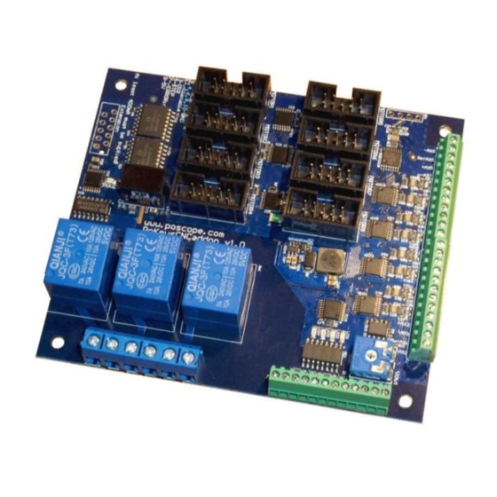
125 kHz, dedicated limit+, limit-, home/ref, axis error inputs, 3 relay outputs, 4 open-collector outputs, 0-10 V output) using PoKeysCNCaddon (pictured below). PoKeysCNCaddon inputs and outputs are galvanically isolated from PoKeys board. Figure 2: PoKeysCNCaddon v1.0 www.poscope.com... -
Page 7: Pokeys Device Pins In Use
(external 470 Ω pull-up resistor needed) Emergency switch input Safety charge pump 5 kHz output Inputs for limit, home and probing switches can be freely connected to any PoKeys pin and configured in software. Remarks: Watch for pin 47! It is not used for step output! All switch inputs expect normally closed (NC) switches and must be connected between specified PoKeys input pin and ground. -
Page 8: External Pulse Generator With Dedicated Io Capability - Up To 8 Axes At 125 Khz Step Frequency
External pulse generator with dedicated IO capability - up to 8 axes at 125 kHz step frequency Please pay attention to connecting the PoKeysCNCaddon to PoKeys device. PoKeysCNCaddon connects to PoKeys using the Expansion port flat cable, attached to the board. The Expansion port signals should be connected to PoKeys as follows: Description... -
Page 9: 10-Pin Motor Driver Connector Pinout
PoKeys Pulse engine v2 documentation 10-pin motor driver connector pinout Function Axis enable output Direction output Step output Error input 2, 4, 6, 8, 10 Not connected Dedicated axis switch inputs All inputs have built-in pull-up resistor - switches must be connected between... -
Page 10: Open-Collector Outputs
PoKeys Pulse engine v2 documentation Open-collector outputs PoKeysCNCaddon board features 4 open-collector outputs with LEDs for signaling the output state. Rating: Maximum applied voltage: 80 V Maximum DC current: up to 50 mA 0-10 V voltage output PWM signal is used to create the 0-10 V voltage output. PWM signal with 0% duty cycle produces 0 V on output, while 100% duty cycle produces Vmax on output. -
Page 11: Pulse Engine Limitations
PoKeys Pulse engine v2 documentation Pulse engine limitations: Minimum/maximum position: Internal motion controller: -/+ ~16.8 million ticks External (buffered) mode: -/+ ~2100 million ticks www.poscope.com... -
Page 12: Pokeys Mach3 Plugin
PoKeys Mach3 plugin Installing plugin In order to install PoKeys Mach3 plugin, simply copy the Pokeys.dll to the Mach3 plugin folder (by default C:\Mach3\Plugins\). Also, install the latest PoKeys software using the provided setup file. PoKeys Mach3 plugin existing functionality... - Page 13 Enable the Pokeys-Polabs plugin and click CONFIG to start configuring the plugin. PoKeys plugin support multiple PoKeys devices (PoKeys55, PoKeys56U and PoKeys56E). To add a new device configuration, click the ‘Add new’ button and select the PoKeys device (as illustrated in the image below).
-
Page 14: Enabling Pulse Engine
On the next Mach3 startup, the following dialog will appear, notifying you that the motion control hardware plugin was detected. Select PoKeys-Polabs and click OK. To enable Pulse engine, the emergency switch input must be connected between pin 52 and ground. -
Page 15: Motors/Axis Setup
PoKeys Pulse engine v2 documentation Motors/axis setup Open Config > Ports & Pins. The following dialog will appear. Please check that the X, Y and Z axis are enabled (enable A Axis if external pulse generator is used). Other settings are ignored. - Page 16 PoKeys Pulse engine v2 documentation www.poscope.com...
-
Page 17: Axis Switches Configuration
PoKeys digital input pin (the latest is the only option to use when using integrated pulse engine or external pulse engine without IO functionality). -
Page 18: Setting Up Digital Inputs And Outputs Mapping
LEDs. If the pin function is set to 'Input', this mapping will enable setting of Mach3 OEM LED state based on PoKeys IO pin state. If the pin function is set to 'Output', Mach3 OEM LED state will be reflected to PoKeys IO pin state. -
Page 19: Pendant Mode
PoKeys Pulse engine v2 documentation Pendant mode Plugin supports the usage of pendant with activation switch. If such pendant is connected to PoKeys, 'Pendant mode' should be enabled (checkbox at the bottom of the 'PoKeys mapping' dialog). In this mode, jog action will be deactivated when the activation switch is released and will be automatically activated when there is a signal detected for both the axis and step selection. -
Page 20: Popendant Configuration
'Import' and select the PoPendant configuration file). Note: the following table only gives an example on how to connect the PoPendant to PoKeys device. To ease the setup process, the configuration file for this example is provided on PoPendant homepage. -
Page 21: Encoder (Mpg) Settings
Mach3 OEM DRO mapping. The option in the last column 'Pendant' tells PoKeys plugin which encoder is used as MPG on the pendant. In case the 'Pendant mode' is enabled and there is an invalid signal from connected pendant, changes of encoders marked with 'Pendant' will have no effect on Mach3 or motion. - Page 22 Column connections To setup mapping of matrix keyboard keys to OEM LEDs and buttons, go back to 'PoKeys mapping' tab and select appropriate functions for the matrix keyboard entries in the list of available IOs. www.poscope.com...
- Page 23 PoKeys Pulse engine v2 documentation LCD setup The LCD configuration dialog can be used to enable LCD, select connection option (primary or secondary pins, as defined in the PoKeys manual), select LCD size and edit contents of the LCD. Enable LCD and 'Edit contents'...
- Page 24 PoKeys Pulse engine v2 documentation PWM (Pulse-width modulated) outputs PoKeys devices support up to 6 pulse-width modulated digital outputs. All outputs share the same PWM total period (specified in microseconds) and have separetely configurable duty cycles. Duty cycles can be specified either in 0-100% or as raw PWM duty cycle period in microseconds.
- Page 25 PoKeys Pulse engine v2 documentation Analog inputs Available analog inputs on the PoKeys device (pins 43-47 on PoKeys55 and pins 41-47 on PoKeys56) can be either mapped to Mach3 OEM DRO register or used as an analog joystick axis, used for jogging.
-
Page 26: Pokeys Io Status
PoKeys Pulse engine v2 documentation PoKeys IO status This tab gives the user an overview of the PoKeys inputs and outputs. PoKeys pins are represented as a grid of colored squares, each resembling a single PoKeys pin and encoder values are listed at the bottom of the dialog. -
Page 27: Reading And Writing Of Io From Vb Script
Mach3 DRO number, specified in the field on the right (values between 1000 and 2255 are valid). If 'Use slots 21-27 to send data from Mach3 to PoKeys' option is enabled, slots 21 to 27 are read from specified Mach3 DRO registers and sent to PoKeys PoIL core. -
Page 28: Example Script
Return - Return of 0 if there are no faults, 1 is returned if he pin is not found , 2 is returned if the pin is an output pin. Example script (finds the PoKeys device with the serial number 25000, then toggles the IO 1 on and off at a rate of 1 Hz): Sub Main() DevName = "PoKeys_25000"... -
Page 29: Additional Oem Buttons
PoKeys Pulse engine v2 documentation Additional OEM buttons OEM button Function 1900 Plugin Jog Toggle 1901 Plugin Jog + 1902 Plugin Jog - 1903 Plugin Rapid Jog Toggle 1904 Plugin Goto 0's 1910 Plugin Spindle CW 1911 Plugin Spindle Stop... -
Page 30: Pulse Engine V2 Operating Principles
PoKeys Pulse engine v2 documentation Pulse engine v2 operating principles PoKeys Pulse engine v2 (upgrade of the original PoKeys Pulse engine) is available on PoKeys56U and PoKeys56E devices and enables a direct control of a positioning systems that accepts step/direction signals (stepper motors, servo systems, etc.). -
Page 31: Modes Of Operation
The position of the axes is saved and the motion is stopped. (MPG) Jogging: if axis has an MPG assigned, the MPG jog is done by PoKeys device itself using the MPG multiplier value. -
Page 32: Safety Charge-Pump Output
Custom external pulse generator without IO functionality External pulse generator is a simple circuit for deserializing step and direction data, coming from PoKeys device. The circuit uses 74HCT595 IC that is connected to PoKeys board as shown in the table below. - Page 33 PoKeys Pulse engine v2 documentation 100n GNDi DATA STEP+1 DIR+1 CLOCK STEP+2 DIR+2 /SCLR STEP+3 LATCH DIR+3 STEP+4 DIR+4 DATA to next 4 axes GNDi 74HCT595 GNDi www.poscope.com...
- Page 34 PoKeys Pulse engine v2 documentation www.poscope.com...
-
Page 35: Frequently Asked Questions
- ones expect active low signal for enabling the outputs, the others expect active high signal. Since PoKeys is not a LPT port extension, the Mach3's Ports & Pins is not functional and all configuration is done via PoKeys plugin configuration dialogs. - Page 36 16. The licensee agrees to allow access to this software only to persons who have been informed of and agree to abide by these conditions. 17. Trademarks: Windows is a registered trademark of Microsoft Corporation. PoKeys, PoKeys55, PoKeys56U, PoKeys56E, PoScope, PoLabs and others are internationally registered trademarks.
Need help?
Do you have a question about the 56U and is the answer not in the manual?
Questions and answers