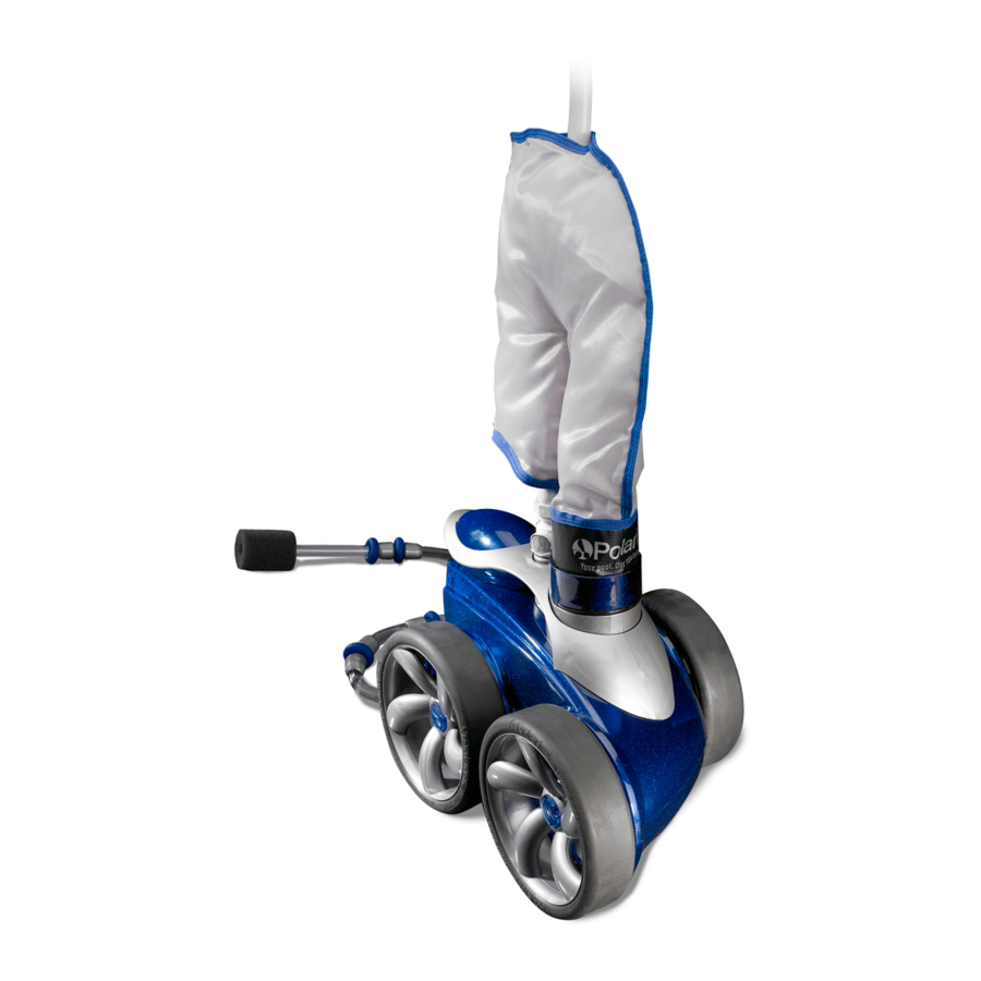
Polaris 3900 sport Service Manual
Pressure pool cleaner
Hide thumbs
Also See for 3900 sport:
- Instructions for installation and use manual (53 pages) ,
- Owner's manual (33 pages) ,
- Quick start manual (2 pages)
Table of Contents
Advertisement
Advertisement
Table of Contents

Related Manuals for Polaris 3900 sport


Summary of Contents for Polaris 3900 sport
- Page 1 POLARIS® 3900 SPORT TEARDOWN WORKBOOK...
-
Page 3: Important Safety Instructions
IMPORTANT SAFETY INSTRUCTIONS The information contained in this technical guide is intended for Zodiac trained service personnel only. Electrical installation and repairs should only be performed by a certified electrician or Zodiac trained professional. and must comply with all national electric codes (NEC, Canadian, etc.). state and local law, ordinances, codes and regulations. - Page 4 Zodiac® Pool Systems, Inc. Zodiac Academy 1-800-822-7933 zodiac.academy@zodiac.com Regional Extension_________________ www.trainyu.com/zodiac www.ZodiacPoolSystems.com Instructor: __________________________________________________ ext. _______ Sales person: ________________________________________________ ext. _______ Service Manager: ____________________________________________ ext. _______ Notes:...
-
Page 5: Table Of Contents
TABLE OF CONTENTS TABLE OF CONTENTS TABLE OF CONTENTS DISASSEMBLY BAG SWEEP HOSE REMOVAL..............6 BOTTOM HOUSING REMOVAL ..............7 WATER MANAGEMENT REMOVAL ............. 8 WHEEL REMOVAL ..................9 GEAR BOX ASSEMBLY ................10 TOP ASSEMBLY .................... 11 DRIVE TRAIN ....................11-16 PRODUCT BREAKDOWN .................. -
Page 6: Disassembly
DISASSEMBLY BAG AND SWEEP HOSE REMOVAL Press logo buttons to remove Quick Disconnect Remove bag by twisting collar Remove Sweep hose by twisting nut to release from hose... -
Page 7: Bottom Housing Removal
DISASSEMBLY BOTTOM HOUSING REMOVAL Remove 3 screws from bottom of cleaner Remove Bottom Housing Locate 3 screws labeled “A” and remove. -
Page 8: Water Management Removal
DISASSEMBLY GEAR BOX REMOVAL Remove Water management System and Rear Housing Locate 4 screws labeled “B” and remove Remove Gearbox and single side wheel... -
Page 9: Wheel Removal
DISASSEMBLY GEAR BOX REMOVAL Pry hubcap with flat-blade screw- driver for removal Un-thread screw to remove wheel Pull wheel from gearbox shaft... -
Page 10: Gear Box Assembly
DISASSEMBLY GEAR BOX COMPONENTS Gearbox Assembly Part #39-200 Notes:... -
Page 11: Top Assembly
DISASSEMBLY TOP ASSEMBLY REMOVAL Locate and remove 2 screws in order to remove the Top. Remove Top Top Assembly Part #39-003, includes float. - Page 12 DISASSEMBLY DRIVE TRAIN REMOVAL Pry hubcap off double-side wheels with flat-blade screw driver Un-thread screw to remove wheel. Remove wheel.
- Page 13 DISASSEMBLY DRIVE TRAIN REMOVAL Remove wheel sprocket cover to expose chain Remove chain from rear wheel sprocket Remove Sprocket and note bearing placement...
- Page 14 DISASSEMBLY DRIVE TRAIN REMOVAL Press bearing out with screw- driver and inspect Reinstall bearing with open face into Sprocket Press against closed face of bearing...
- Page 15 DISASSEMBLY DRIVE TRAIN REMOVAL Sprocket Assembles and chain Drivetrain Locate and remove wheel spac- ers from 2 wheel side axles Locate and remove 2 screws at the base of the feed pipe...
- Page 16 DISASSEMBLY DRIVE TRAIN REMOVAL Remove the Vacuum Tube/ Feed pipe assembly. Locate and remove the 2 screws that attach each axle to the frame. Frame assembly with Chain tensioner.
-
Page 17: Product Breakdown
COMPONENTS Product Breakdown Notes:... -
Page 18: Component Parts
PART NUMBERS... -
Page 19: Reassembly
ASSEMBLY REASSEMBLY Assemble axle blocks with star washers and screws. Turn frame upside down and install axle blocks to frame. Drop gearbox into place with Brass Brass brass inserts pointing up. Inserts Inserts... -
Page 20: Gear Box
ASSEMBLY REASSEMBLY Attach gearbox with 4 screws in pockets labeled “B”. Install wheel spacers on double side wheel axle blocks. Attach Vacuum tube/Feed pipe Assembly to frame with 3 screws. -
Page 21: Wheels & Chain
ASSEMBLY REASSEMBLY Install Wheel Sprockets on double side axle. Wrap chain around front axle sprocket and through tensioner as shown. - Page 22 ASSEMBLY REASSEMBLY Use the diagram on the Vacuum tube to assist with wrap configuration. Install the 2 sprocket covers. Locate double side wheel noting one bearing in the outer cavity of each wheel.
- Page 23 ASSEMBLY REASSEMBLY Align wheels into sprockets and attach with locking screw. Locking screw Attach single side wheel with the same locking screw.
-
Page 24: Top Assembly
ASSEMBLY REASSEMBLY Replace top assembly with 2 screws. Inspect o-ring on Water management System. Snap rear housing to Water management System. -
Page 25: Water Management
ASSEMBLY REASSEMBLY Attach Water management System with 3 screws. Align bottom housing. -
Page 26: Bottom & Sweep Hose
ASSEMBLY REASSEMBLY Attach bottom housing with 3 screws Snap hub caps on all wheels. Attach sweep hose - install nut first then thread back onto sweep hose. -
Page 27: Bag & Quick Disconnect
ASSEMBLY REASSEMBLY Note the serial number location under the canopy. Press bag into vacuum tube. Install quick disconnect. - Page 28 Notes:...
- Page 29 Notes:...
- Page 30 DVS 3900 JUN 2015...
Need help?
Do you have a question about the 3900 sport and is the answer not in the manual?
Questions and answers