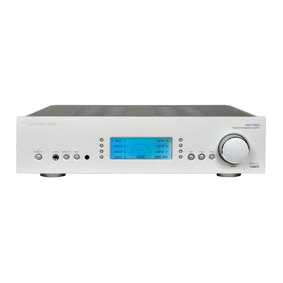
Cambridge Audio 840A Service Manual
Hide thumbs
Also See for 840A:
- User manual (26 pages) ,
- White paper (23 pages) ,
- Supplementary manual (5 pages)
Table of Contents
Advertisement
Issue Date: 16th June 2006
________________________________________________________________________________
SERVICE MANUAL
________________________________________________________________________________
SPECIFICATIONS:
Power Output
THD (unweighted)
Frequency Response
S/N ratio (ref 1W/8 Ohm)
Input Impedances
Power Amp damping factor
Max power consumption
Minimum power consumption
Bass & Treble controls
Dimensions (H x W x D)
Weight
Gallery Court Hankey Place London SE1 4BB UK
Tel: +44 (0)20 7940 2200 Fax: +44 (0)20 7940 2233
120W RMS into 8 Ohms
200W RMS into 4 Ohms
< 0.0015% 1 kHz
at 80% of rated power
< 0.015% 20Hz – 20kHz
at 80% of rated power
10Hz – 50kHz +/- 1dB
>83dB
Input 1 (balanced) 10 kOhm
Inputs 2-7 68 kOhm
Tape Input 68 kOhm
> 110 at 1kHz
800W
Active (no signal) 70W
Standby 7W
Shelving type
Max bass boost/cut +/- 10dB at 10Hz
Max treble boost/cut +/- 7.5dB at 20Hz
115 x 430 x 385mm
(4.5 x 16.9 x 15.2")
15.0kg (33Lbs)
840A
AP19597/1
1
Advertisement
Chapters
Table of Contents

Related Manuals for Cambridge Audio 840A


Summary of Contents for Cambridge Audio 840A
-
Page 1: Service Manual
840A Issue Date: 16th June 2006 ________________________________________________________________________________ SERVICE MANUAL ________________________________________________________________________________ SPECIFICATIONS: Power Output 120W RMS into 8 Ohms 200W RMS into 4 Ohms THD (unweighted) < 0.0015% 1 kHz at 80% of rated power < 0.015% 20Hz – 20kHz at 80% of rated power Frequency Response 10Hz –... -
Page 2: Table Of Contents
840A SERVICE MANUAL TABLE OF CONTENTS Safety Precautions & Important Notes Block Diagram Exploded Diagram Exploded Diagram Parts List Front Panel PCB Schematic (Microcontroller & LCD) Front Panel PCB Schematic (Shift Registers) Front Panel PCB Layout (Top Side) Front Panel PCB Layout (Bottom Side) - Page 3 Hub PCB Board Layout (Top Side) Hub PCB Board Layout (Bottom Side) Hub PCB BOM 42-43 Rectifier PCB Schematic Rectifier PCB Board Layout (Top Side) Rectifier PCB Board Layout (Bottom Side) Rectifier PCB BOM IC Pin Layout Details 48-49 Technical Description 51-60 Procedure to upgrade the Control (Pic) Software 61-62...
-
Page 4: Safety Precautions & Important Notes
COPYRIGHT NOTICE. © 2007 Audio Partnership PLC. All rights reserved. Cambridge Audio and Azur are registered trademarks for Audio Partnership PLC. This document may not be reproduced, distributed, transmitted, displayed, published, or broadcast without the express written prior permission of Audio Partnership PLC. -
Page 5: Block Diagram
Cambridge Audio Azur 840A Amplifier To enhance viewing, please print to A3 840A Block Diagram... -
Page 6: Exploded Diagram
Cambridge Audio Azur 840A Amplifier To enhance viewing, please print to A3 840A Exploded Diagram... -
Page 8: Front Panel Pcb Schematic (Microcontroller & Lcd)
Cambridge Audio Azur 840A Amplifier +15V +15V COL 1 COL 2 COL 3 COL 4 RS232 RX ON/STBY LED SW-TACT SW-TACT SW-TACT SW-TACT ROW 1 LOGIC GND BLUE LED INPUT 1 INPUT 2 INPUT 3 INPUT 4 SPEAKER TEST SERIAL RX 232... -
Page 9: Front Panel Pcb Schematic (Shift Registers)
Cambridge Audio Azur 840A Amplifier SERIAL DATA SERIAL CLOCK FROM SHEET 1 SERIAL STROBE SHIFT REG ENABLE TO PREAMP BOARD FFC 08WAY 74HC4094 VDD=+5V VSS=LOGIC GND TO PREAMP BOARD FFC 08WAY 74HC4094 VDD=+5V VSS=LOGIC GND 100nF 100nF 100nF 100nF SHIFT REG DECOUPLE... -
Page 10: Front Panel Pcb Layout (Top Side)
Cambridge Audio Azur 840A Amplifier ROT1 SW10 SW11 (c) COPYRIGHT Audio Partnership PLC 2005 AP16370/3 AP16370/3 To enhance viewing, please print to A3 AP16369/3 Front Panel PCB Layout (Top Side) -
Page 11: Front Panel Pcb Layout (Bottom Side)
Cambridge Audio Azur 840A Amplifier To enhance viewing, please print to A3 AP16369/3 Front Panel PCB Layout (Bottom Side) -
Page 12: Front Panel Pcb Bom
AP16372/5 Cambridge Audio Azur 840A Amplifier Front Panel PCB BOM AP No Value Description/Type Component Ident Notes RESISTORS 0.25 W 1% Metal Film R10, R23, R24 0.25 W 1% Metal Film 0.25 W 1% Metal Film 0.25 W 1% Metal Film 100R 0.25 W 1% Metal Film... -
Page 13: Input Pcb Schematic (Input Select)
Cambridge Audio Azur 840A Amplifier 22pF 22pF LEFT CN10 RIGHT INPUT 1 R+ INPUT ONE RIGHT + -15V U14:B INPUT 1 R- INPUT ONE RIGHT - U14:A RL1:B RL1:C NE5532 NE5532 INPUT 1 L- INPUT 1 R- INPUT 1 L+... -
Page 14: Input Pcb Schematic (Input Control)
Cambridge Audio Azur 840A Amplifier INPUT PCB - PREAMP PCB TAPE MONITOR RL1:A RL2:A RL3:A RL4:A RL5:A RL6:A RL7:A RL8:A TO PREAMP LEFT TO PREAMP RIGHT PREAMP OUT L 1N4001 PREAMP OUT R RELAY RELAY RELAY RELAY RELAY RELAY RELAY... -
Page 15: Input Pcb Schematic (Input Amplifier)
Cambridge Audio Azur 840A Amplifier +15V INPUT L U2:B TO PREAMP LEFT 10U 16V NP NE5532 1000uF 10V EL 100K 100K -15V 1N4001 INPUT AMPLIFIER + 6 dB +15V U4:B INPUT R TO PREAMP RIGHT 10U 16V NP 1000uF 10V EL... - Page 16 Cambridge Audio Azur 840A Amplifier TAPE OUT PREAMP OUT RELAY DRIVER LOGIC HUB SWITCHER AP16362/3 AP16362/3 To enhance viewing, please print to A3 AP16361/3 Input Board PCB Board Layout (Top Side)
- Page 17 Cambridge Audio Azur 840A Amplifier To enhance viewing, please print to A3 AP16361/3 Input Board PCB Board Layout (Bottom Side)
-
Page 18: Input Pcb Bom
AP16364/3 Cambridge Audio Azur 840A Amplifier Input PCB BOM RESISTORS l a t l a t R4, R5, R8, R10, R15-R18, R26, R27, l a t R31, R33, R36, R37, R48-R51 l a t l a t R41, R43, R44, R46, R55, R56, R65,... -
Page 19: Preamp Pcb Schematic (Relay Logic)
Cambridge Audio Azur 840A Amplifier INPUT PCB - PREAMP PCB FRONT PCB - PREAMP PCB +15V CN11 R104 SPEAKER TEST ON/STBY LED IR RX LOGIC GND LOGIC GND PHONES DETECT 10U 16V 100n ceramic +15V OVERLOAD -15V CLIP DETECT DC OFFSET... -
Page 20: Preamp Pcb Schematic (Tone Control)
Cambridge Audio Azur 840A Amplifier RL15:C SW1:A RELAY RL15:B U9:B 470U 10V EL SW-DPDT NE5532 DEFEAT 10U NP 16V TO VOLUME LEFT RELAY 1N PE 63V 150R +15V RL17:B RL18:B RL19:B TREBLE ALPHA RD902PF 1000U 10V EL VR1:B 47N PE 63V... -
Page 21: Preamp Pcb Schematic (Post Amp)
Cambridge Audio Azur 840A Amplifier +15V R106 PREAMP OUT L 470R 47U NP 25V R107 47N PE 63V 100nF ceramic -15V U12:A CN10 AUDIO TO L POWER AMP VOL OUT LEFT 10U NP 16V 220R NE5532 JST 2.5MM B2B-XH-A 100nF ceramic... - Page 22 Cambridge Audio Azur 840A Amplifier RL10 RL11 RL12 RL13 RL14 RL17 RL18 RL19 RL16 RL15 R108 R106 R107 R109 CN11 CN12 CN10 PHONES R26 R52 R24 R50 R103 To enhance viewing, please print to A3 AP16365/3 Preamp PCB Layout (Top Side)
- Page 23 Cambridge Audio Azur 840A Amplifier To enhance viewing, please print to A3 AP16365/3 Pre-amp PCB Layout (Bottom Side)
-
Page 24: Preamp Pcb Bom
AP16368/4 Cambridge Audio Azur 840A Amplifier Preamp PCB BOM AP No Value Description/Type Component Ident Notes RESISTORS l a t l a t l a t l a t R85, R86, R92, R96, R75, R78, R76, l a t l a t... -
Page 25: Preamp Pcb Bom
AP16368/4 Cambridge Audio Azur 840A Amplifier Preamp PCB BOM AP No Value Description/Type Component Ident Notes MISCELLANEOUS Retractable 9mm pot. With centre PY1156 RD902PF-20B6-30F-B5K-0C ALPHA B5K LINEAR POT VR1, VR2 detent. CK-6.35-04 7P HEADPHONE JACK SKT JST 2,5MM B2B-XH-A 2-way vertical header... - Page 26 Cambridge Audio Azur 840A Amplifier 36 V 5.5A MAINS ON/OFF RELAY X1 10n ORANGE TO POWER AMP SUPPLY LEFT RL3:B (SEPARATE PCB) ME14FW009HS Secondary YELLOW INRUSH CONTROL RELAY MAIN TRANSFORMER 36 V 10A for 115V X1 10n MAINS IN 5.5A...
- Page 27 Cambridge Audio Azur 840A Amplifier +48V R PHONES OUT RIGHT 220R 3W C 150R 100R 220uF 80V 1N4148 1N4148 47uF 16V 47uF 35V 470R 1W C 100R 1N4148 1N4148 2SA1295 2SA1295 MPSA93 MPSA93 RL1:C LEFT IN LEFT OUT A MPSA93...
- Page 28 Cambridge Audio Azur 840A Amplifier To enhance viewing, please print to A3 AP16373/3 Power Amp (Right) & PSU PCB Layout (Top Side)
- Page 29 Cambridge Audio Azur 840A Amplifier To enhance viewing, please print to A3 AP16373/3 Power Amp Right & PSU PCB Layout (Bottom Side)
-
Page 30: Power Amp Right Pcb Bom
AP16376/7 Cambridge Audio Azur 840A Amplifier Power Amp Right PCB BOM RESISTORS 910R 0.125 W Metal Film 0.125 W Metal Film 0.125 W Metal Film R36 , R66, R68, R72, R74, 0.125 W Metal Film R16, R69, R75, R76, R77, R85, 0.125 W Metal Film... -
Page 31: Power Amp Right Pcb Bom
AP16376/7 Cambridge Audio Azur 840A Amplifier Power Amp Right PCB BOM 16V Electrolytic Radial 47uF C1, C8, C9 (5mm) Pitch= 2.5mm 35V Electrolytic Radial 47uF (10mm) Pitch= 2.5mm 100V Electrolytic Radial 220uF (12.5mm) Pitch= 5mm 80V Electrolytic Radial 220uF (10.4mm) Pitch= 5mm... - Page 32 AP16376/7 Cambridge Audio Azur 840A Amplifier PSU PCB BOM RESISTORS l a t 10R 10W 8.5X53MM s i s WireWound l a t l a t CAPACITORS 10nF X1 MEX103K300A02 Pitch =10mm C29, C30, C34-C37 Capacitor 100nF Ceramic 100V Pitch= 5mm...
- Page 33 Cambridge Audio Azur 840A Amplifier +48V 150R 100R 1N4148 220uF 80V 1N4148 47uF 16V 47uF 35V 100R 1N4148 1N4148 2SA1295 2SA1295 MPSA93 MPSA93 PHONES L MPSA93 MPSA93 220R 3W C MJE340 100R NORMAL = HI 1N5404 CLIP 470R 1W C...
- Page 34 Cambridge Audio Azur 840A Amplifier FROM RECTIFIER BOARD +48V 36 V +48V IN 5.5A TERMINAL 15000U 63V POWER AMP SUPPLY LEFT ORANGE 0V IN TERMINAL ORANGE Secondary 15000U 63V -48V YELLOW MAIN TRANSFORMER -48V IN 36 V TERMINAL 5.5A YELLOW...
-
Page 35: Power Amp Pcb Board Layout (Top Side)
Cambridge Audio Azur 840A Amplifier FIX1 To enhance viewing, please print to A3 AP16693/5 Power Amp PCB Board Layout (Top Side) -
Page 36: Power Amp Pcb Board Layout (Bottom Side)
Cambridge Audio Azur 840A Amplifier To enhance viewing, please print to A3 AP16693/5 Power Amp PCB Board Layout (Bottom Side) -
Page 37: Power Amp Left Pcb Bom
AP16696/9 Cambridge Audio Azur 840A Amplifier Power Amp Left PCB BOM i r c RESISTORS 0.125 W Metal Film 100R 0.125 W Metal Film R86, R90, R91 910R 0.125 W Metal Film 0.125 W Metal Film R36, R42, R46, R68, R75, R89 0.125 W Metal Film... -
Page 38: Power Amp Left Pcb Bom
AP16696/9 Cambridge Audio Azur 840A Amplifier Power Amp Left PCB BOM i r c 35V Electrolytic Radial 47uF (10mm) Pitch= 2.5mm 16V Electrolytic Radial (5mm) 47uF C1, C8, C9 Pitch= 2.5mm 80V Electrolytic Radial 220uF C4, C5 (10.4mm) Pitch= 5mm... -
Page 39: Hub Pcb Schematic
Cambridge Audio Azur 840A Amplifier +12V +24V IN +24V LOOKING AT LEADS INPUT 1: BALANCED INPUTS 7812 10R 2W 1N4004 POLYFUSE 1-1A XLR FEMALE 78L12 220U 35V EL 100nF 100nF RIGHT RICCO PCB JACK 10uF 25V +24V IN ABUS GND... - Page 40 Cambridge Audio Azur 840A Amplifier RS232 AP16378/3 AP16378/3 To enhance viewing, please print to A3 AP16377/3 Hub PCB Layout (Top Panel)
- Page 41 Cambridge Audio Azur 840A Amplifier To enhance viewing, please print to A3 AP16377/3 Hub PCB Layout (Bottom Panel)
- Page 42 AP16380/5 Cambridge Audio Azur 840A Amplifier Hub Board BOM RESISTORS l a t R4, R9, R14, R26, R27, R32, R33, l a t R40, R41 R10, R28, R42, R43, R47, R48, R51, l a t R52, R54, R55 l a t...
- Page 43 AP16380/5 Cambridge Audio Azur 840A Amplifier Hub Board BOM Dual phono socket with EMC gnd AV2-8,4-14/EC CN10 Orange inserts Vertical FFC conn, reverse-needle PY1143 D100-SSV-10 type single-row contacts 10-way Vertical FFC conn, reverse-needle PY1142 D100-SSV-13 type CN15 single-row contacts 13-way .
-
Page 44: Rectifier Pcb Schematic
Cambridge Audio Azur 840A Amplifier T6A3 AL +48V OUT 36 V TERMINAL LVD! VIOLET TERMINAL 5.5A 10nF ORANGE ORANGE GREEN TERMINAL TERMINAL BRIDGE BR-254 10nF Secondary -48V OUT 10nF TERMINAL BLUE YELLOW MAIN TRANSFORMER 36 V 5.5A T6A3 AL TERMINAL... - Page 45 Cambridge Audio Azur 840A Amplifier AUDIO PARTNERSHIP 2005 To enhance viewing, please print to A3 AP17575/2 Rectifier Board PCB Board Layout (Top Side)
- Page 46 Cambridge Audio Azur 840A Amplifier To enhance viewing, please print to A3 AP17575/2 Rectifier Board PCB Board Layout (Bottom Side)
-
Page 47: Rectifier Pcb Bom
Cambridge Audio Azur 840A Amplifier, Rectifier PCB BOM AP17578/2 AP No Value Description/Type Component Ident Notes CAPACITORS 10nF X1 Capacitor MEX103K300A02 Pitch =10mm C14-C16 DIODES Rectifier is not soldered to PCB until Bridge Rectifier BR254 400PIV 25A blk metal case... -
Page 48: Ic Pin Layout Details
Cambridge Audio Azur 840A Amplifier IC Pin Layout Details TC9163AF – Input PCB (U1) NE5532 Input PCB - (U2, U3, U4, U5, U6, U7, U8, U9, U14 & U18) A-BUS PCB – (U1 & U3) Pre-Amp PCB – (U1, U2, U9 & U12) - Page 49 74HC4094 Front Panel PCB - (U2, U3, U4, U5 & U6) BC327 Front Panel PCB - (Q1 & Q8) A-BUS PCB – (Q1) LM393AP Right Hand Power Amp PCB - (U1) Left Hand Power Amp PCB – (U1) MJE340 Right Hand Power Amp PCB - (Q1, Q12 & Q18) Left Hand Power Amp PCB –...
- Page 50 2SA1295 Right Hand Power Amp PCB - (Q13, Q14 & Q17) Left Hand Power Amp PCB – (Q13, Q14 & Q17) 2SC3264 Right Hand Power Amp PCB - (Q15 & Q16) Left Hand Power Amp PCB – (Q15 & Q16) CD4011BE A-BUS PCB - (U7) 7812...
-
Page 51: Technical Description
Updated: 29 Nov 05 Revision history V1->V2 More info added to operating instructions summary This document gives a concise guide to the operation of the 840A XD amplifier. CONTENTS Azur 840A power supply PCB AP16373/3_B Azur 840A front panel PCB... - Page 52 The Power Supply PCB This carries: Power supplies for everything except power amps Mains on/off and inrush control switching relays X2 capacitor The mains-fail detect circuit There are four power supply rails: +15V Opamp supply -15V Opamp supply +9V Relay supply +5V Microcontroller, logic and comparator supply The power supply board also carries the mains switching relays that control the supplies to the power amplifiers.
- Page 53 The relays on the other PCBs are controlled by a set of shift registers that convert serial data from the PIC into 32 latched outputs. Four shift registers (U3,U4,U5,U6) are connected so that the serial input enters the first register and is clocked through and out of its serial output into the serial input of the second register.
- Page 54 The Preamplifier PCB The preamplifier PCB carries: The tone controls and DIRECT switch Relay balance control Balance control buffer Amplifier Relay volume control Volume control post amplifier Relay drivers ON/standby LED control The IR receiver Headphone socket All component numbers here refer to the Left channel. The balance control operates in discrete steps selected by relays.
-
Page 55: Speaker Short-Circuit Detect
The volume control and balance relays are driven from three 8-bit serial-in parallel-out (SIPO) shift registers on the front panel PCB. The logic signals come in on CN6, CN8 and CN9, and control the 7- way open-collector relay drivers U4,U5,U7. Driver U7 also controls the mains on/off and inrush relays, (on the PSU PCB) the two amplifier output relays, (on the right amplifier PCB). - Page 56 The XD control circuit is a differential pair of transistors with one input grounded and the other driven by the main amplifier output voltage, scaled down appropriately by R63, R64. The drive to the displacer is taken from collector load R58, to give the required phase inversion. R59 is present simply to equalise the dissipation in the differential pair transistors to maintain their balance.
- Page 57 Clip detection. When it is enabled, the clip-detect system turns down the volume when excess clipping of either amplifier output occurs. Very brief episodes of clipping are ignored. The volume stays reduced and does not ramp back up in the absence of clipping. The clip detect system is based on Q23, Q24 and associated components.
- Page 58 Control Hub input switcher from IR commands Send input select data to main PIC Control Hub input switcher to prevent thumps on 840A output Control A-bus status line IR commands to the A-bus keypads are sent to the hub so that the required input can be selected and external equipment controlled.
- Page 59 The Hub PIC controls the A-bus status line so that it is high when the 840A is powered and low when it is not. It also implements the “all off” feature; when this command is received from one keypad the Hub PIC ensures that both are turned off.
- Page 60 To rename inputs: Press and hold the relevant input select button. Letters in the name are selected by turning the volume knob. To access the configuration menu: Press and hold the Mode button. These are the menu options: Clip detector on/off LCD brightness (off/dim/bright) Input gain trim menu access Volume ramp on/off...
- Page 61 840A Software Loading Instructions 1) Push and hold the “Standby / On” on the front of the 840A whilst turning on the power switch at the rear. After about 4 seconds the following should be displayed on the LCD: 2) Connect a Null Modem RS232 cable from the 840A to the PC’s comm port.
- Page 62 5) Click the Load File button, the following window will be displayed: Locate the file “840A.hex” and click open. The following window should be displayed: 6) Click the Download Code button, “Loading…” will be displayed on the LCD. The ABUS processor will be programmed followed by the Main processor.
-
Page 63: Notes
840A ________________________________________________________________________________ Notes. Gallery Court Hankey Place London SE1 4BB UK Tel: +44 (0)20 7940 2200 Fax: +44 (0)20 7940 2233...
Need help?
Do you have a question about the 840A and is the answer not in the manual?
Questions and answers