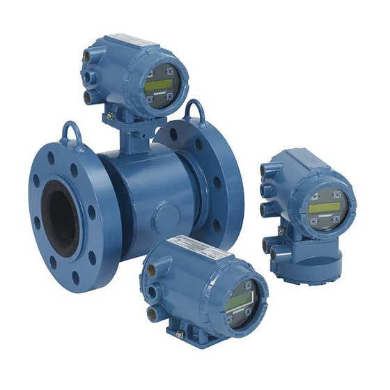
Rosemount Series 8700 Manual
Magnetic flowmeter flowtubes
Hide thumbs
Also See for Series 8700:
- Quick installation manual (39 pages) ,
- Quick installation manual (43 pages) ,
- Reference manual (122 pages)
Table of Contents
Advertisement
Advertisement
Table of Contents

Related Manuals for Rosemount Series 8700


Summary of Contents for Rosemount Series 8700
- Page 1 00809-0100-4727 English Rev. CA Series 8700 Magnetic Flowmeter Flowtubes...
- Page 3 For information on Rosemount nuclear-qualified products, contact your local Rosemount Sales Representative. Rosemount, the Rosemount logotype, and SMART FAMILY are registered trademarks of Rosemount Inc. HART is a registered trademark of the HART Communication Foundation. Tefzel and Teflon are registered trademarks of E.I. du Pont de Nemours & Co.
-
Page 5: Table Of Contents
Table of Contents IMPORTANT Procedures and instructions in this manual may require special precautions to ensure the safety of the personnel performing the operations. Refer to the safety messages at the beginning of each section before performing any operations. SECTION 1 Manual Scope . - Page 6 Primary and Secondary Devices ......B-2 Magnetic Flowmeter Oper- Series 8700 Magnetic Flowmeter Flowtube ....B-2 ating Principles Series 8700 Magnetic Flowmeter Transmitter .
-
Page 7: Manual Scope
Section Introduction MANUAL SCOPE The Rosemount Series 8700 Magnetic Flowmeter System combines separate flowtube and transmitter units. This manual is designed to assist in the installation and operation of Rosemount Model 8705, Model 8707 High- Signal, and Model 8711 Magnetic Flowmeter Flowtubes. -
Page 8: System Description
Rosemount Series 8700 Magnetic Flowmeter Flowtube SYSTEM DESCRIPTION A Rosemount Series 8700 Magnetic Flowmeter System measures volumetric flow rate by detecting the velocity of a conductive liquid that passes through a magnetic field. The system consists of two major assemblies: the Model 8705, Model 8707 High-Signal, or Model 8711 Magnetic Flowmeter Flowtubes combined with the Model 8712C/U/H or the Model 8732C Magnetic Flowmeter Transmitters. -
Page 9: Safety Messages
Section Installation This section covers the steps required to physically install the flowtube. Detailed information regarding operation planning and magnetic flowmeter theory is found in the appendices. SAFETY MESSAGES Instructions and procedures in this section may require special precautions to ensure the safety of the personnel performing the operations. -
Page 10: Step 2: Mounting
Conventional tools, equipment, and accessories (bolts, gaskets, MOUNTING and grounding hardware) are required. Calibration Rosemount flowtubes are wet calibrated at the factory. They do not need further calibration during installation. To ensure specification accuracy over widely varying process conditions, Upstream/... -
Page 11: Flowtube Orientation
Installation Flowtube Orientation The flowtube should be installed in a position that ensures the flowtube remains full during operation. Horizontal or inclined positions are preferred. Figures 2-3, 2-4, and 2-5 show the proper flowtube orientation for the most common installations. The following orientations ensure that the electrodes are in the optimum plane to minimize the effects of entrapped gas. -
Page 12: Flow Direction
Rosemount Series 8700 Magnetic Flowmeter Flowtube FIGURE 2-5. FLOW Incline or Decline Orientation. FLOW Flow Direction The flowtube should be mounted so that the FORWARD end of the flow arrow, shown on the flowtube identification tag, points in the direction of flow through the tube (see Figure 2-6). -
Page 13: Step 3: Installation Of Model 8705 And Model 8707 High-Signal
Installation STEP 3: The following drawings should be used as a guide in the installation of the Model 8705 and Model 8707 High-Signal Flowtubes. Refer to page INSTALLATION OF MODEL 2-7 for installation of the Model 8711 Flowtube. 8705 AND MODEL 8707 HIGH-SIGNAL Gaskets The flowtube requires a gasket at each of its connections to adjacent devices... -
Page 14: Flange Bolts
Rosemount Series 8700 Magnetic Flowmeter Flowtube Flange Bolts Flowtube sizes and torque values for both Class 150 and Class 300 flanges are listed in Table 2-1. Tighten flange bolts in the incremental sequence, shown in Figure 2-9. See Tables 5-4, 5-4, and 5-5 for bolt sizes and hole diameters. -
Page 15: Step 3: Installation Of Model 8711
Installation STEP 3: The following section should be used as a guide in the installation of the Model 8711 Flowtube. INSTALLATION OF MODEL 8711 Gaskets The flowtube requires a gasket at each of its connections to adjacent devices or piping. The gasket material selected must be compatible with the process fluid and operating conditions, and must not damage the liner. -
Page 16: Flange Bolts
Rosemount Series 8700 Magnetic Flowmeter Flowtube Alignment with Centering Sleeves Follow the instructions below for the 1.5- through 8-inch (40 to 200 mm) line sizes if you received two centering sleeves instead of centering rings: 1. Insert the two studs for the bottom side of the flowtube, with the centering sleeves, between the pipe flanges. - Page 17 Installation TABLE 2-3. Grounding Installation. Grounding Options Type of Pipe No Grounding Options Grounding Rings Grounding Electrodes Lining Protectors Conductive Unlined Pipe See Figure 2-11 Not Required Not Required See Figure 2-12 Conductive Lined Pipe Insufficient Grounding See Figure 2-12 See Figure 2-11 See Figure 2-12 Non-Conductive Pipe...
- Page 18 Rosemount Series 8700 Magnetic Flowmeter Flowtube FIGURE 2-13. Grounding with Grounding Rings or Lining Protectors. Earth Ground Grounding Rings Lining Protectors FIGURE 2-14. Grounding with Grounding Electrodes. Earth Ground 2-10...
-
Page 19: Step 5: Wiring
Use the stainless steel plug that is provided to seal the unused conduit port. This is a pulsed dc magnetic flowmeter. Series 8700 Flowtubes use a pulsed-dc signal generated by Model 8712C/U/H or Model 8732C Magnetic Flowmeter Transmitter. Never connect AC power to the flowtube;... - Page 20 Rosemount Series 8700 Magnetic Flowmeter Flowtube FIGURE 2-15. Conduit Preparation. Power Power Power Power Coil Drive and Coil Drive and Electrode Cables Electrode Cables Outputs Outputs Outputs Outputs WRONG CORRECT TABLE 2-4. Cable Requirements. Description Signal Cable (20 AWG) 08712-0061-0001...
-
Page 21: Cable Preparation
FIGURE 2-16. Cable Preparation Detail. Cable Shield IMPORTANT Failure to connect the cable shields will result in improper operation. Series 8700 Flowtube Systems require that the cable shields be connected at the flowtube for proper operation. 2-13... -
Page 22: Flowtube To Model 8712C/U Transmitter Connections
Rosemount Series 8700 Magnetic Flowmeter Flowtube Flowtube to Model 8712C/U Connect coil drive and electrode cables as shown in Figure 2-17. Transmitter Connections FIGURE 2-17. Wiring Diagram to Model 8712C/U Transmitter. TABLE 2-5. Rosemount Model 8705/8707/8711 Flowtube Wiring Connections. Rosemount... -
Page 23: High-Signal Flowtube To High-Signal Transmitter Connections
Connect coil drive and electrode cables as shown in Figure 2-18. to High-Signal Transmitter Connections FIGURE 2-18. Wiring Diagram to Model 8712H High-Signal Transmitter. TABLE 2-6. Rosemount Model 8707 Flowtube Wiring Connections. Rosemount Rosemount Model This is a pulsed dc Model 8712H 8707 Flowtubes magnetic flowmeter. -
Page 24: Model 8705 And Model 8711 Flowtube To Model 8732C Transmitter Connections
Rosemount Series 8700 Magnetic Flowmeter Flowtube Model 8705 and Model 8711 Connect coil drive and electrode cables as shown in Figure 2-19. Flowtube to Model 8732C Transmitter Connections FIGURE 2-19. Wiring Diagram for Flowtube and Model 8732C Transmitter. Electronics Board TABLE 2-7. -
Page 25: Nal Only)
Installation STEP 6: The Model 8705 and Model 8707 High-Signal Flowtube housing are fabricated from carbon steel to perform two separate functions in the PROCESS LEAK flowtube design. PROTECTION First, it provides shielding for the flowtube magnetics so that external (MODEL 8705 AND MODEL disturbances cannot interfere with the magnetic field and thus affect 8707 HIGH-SIGNAL ONLY) -
Page 26: Relief Valves
Rosemount Series 8700 Magnetic Flowmeter Flowtube Relief Valves The second configuration, identified by a “W1” model number option code, uses a completely welded coil housing. This configuration does not provide separate electrode compartments with external electrode access. This optional housing configuration provides a relief valve in the... - Page 27 Installation 2-19...
- Page 28 Rosemount Series 8700 Magnetic Flowmeter Flowtube 2-20...
-
Page 29: Flowtube Calibration Number
Section Start-up and Operation This section describes the flowtube calibration numbers for Series 8700 Magnetic Flowtubes. Start-up and operation is dependent upon the transmitter selected to complement the flowtube. For transmitter start-up information, refer to the Model 8712C/U/H product manual 00809-0100-4729 or the Model 8732C product manual 00809-0100-4725. - Page 30 Rosemount Series 8700 Magnetic Flowmeter Flowtube...
-
Page 31: Safety Messages
Failure to follow these installation guidelines could result in death or serious injury: • Make sure only qualified personnel perform the installation. INDEPENDENT Rosemount Inc. flow lab tests determine individual flowtube characteristics and account for them with the 16-digit calibration number. Individual FLOWTUBE AND... -
Page 32: Flowtube Troubleshooting
Rosemount Series 8700 Magnetic Flowmeter Flowtube FLOWTUBE The Model 8712C/U/H and 8732C Magnetic Flowmeter Transmitters performs self diagnostics on the entire magnetic flowmeter system: the TROUBLESHOOTING transmitter, the flowtube, and the interconnecting wiring. While most of the diagnostics are related to the transmitter microprocessor, some tests diagnose specific flowtube problems. -
Page 33: Return Of Materials
Flowtube Housing RETURN OF MATERIALS To expedite the return process outside the United States, contact the nearest Fisher-Rosemount representative. Within the United States and Canada, call the North American Response Center using the 800-654-RSMT (7768) toll-free number. The center is available 24 hours a day and will assist you with any needed information or materials. - Page 34 Rosemount Series 8700 Magnetic Flowmeter Flowtube...
-
Page 35: Functional Specifications
Section Model 8705 and Model 8707 High-Signal Specifications FUNCTIONAL Service Conductive liquids and slurries. SPECIFICATIONS Line Sizes ½ –36 inch (15–900 mm) for Model 8705. 3–36 inch (80–600 mm) for Model 8707. Interchangeability Model 8705 Flowtubes are interchangeable with Model 8712C/U and Model 8732 Transmitters. - Page 36 Rosemount Series 8700 Magnetic Flowmeter Flowtubes Submergence Protection Continuous to 30 feet (10 meters). IP 68. Standard Hazardous Locations Certifications Factory Mutual (FM) Approvals Ordinary locations. Factory Mutual (FM) Approvals (Model 8705 only) Approved for Class I, Division 2, Groups A, B, C, and D; Class II, Division 1, Groups E, F, and G;...
- Page 37 Model 8705 and Model 8707 High-Signal Specifications TABLE 5-2. Flowtube Temperature vs. Pressure Limits. ANSI Class Flanges: ½-inch to 36-inch Line Sizes Pressure in psi PTFE Teflon ETFE Tefzel Natural Rubber Neoprene Polyurethane Liners Flange Rating Liner Liner Liner Liner Liner (@ 100 °F, 37.8 (@ 350 °F, 177 °C)
-
Page 38: Performance Specifications
Rosemount Series 8700 Magnetic Flowmeter Flowtubes PERFORMANCE Accuracy SPECIFICATIONS Model 8705 with Model 8712C/U or Model 8732C ±0.5% of rate from 1 to 30 ft/s (0.3 to 10 m/s). Includes combined effects of linearity, hysteresis, repeatability, and calibration uncertainty. Accuracy is ±0.005 ft/s (±0.0015 m/s) from low-flow cutoff to 1.0 ft/s (0.3 m/s). - Page 39 Model 8705 and Model 8707 High-Signal Specifications Grounding Rings Grounding rings are installed between the flange and the tube face on both ends of the flowtube. They have an I.D. slightly larger than the flowtube I.D. and an external tab to attach ground wiring. Grounding rings are available in 316L SST, Hastelloy C-276, titanium, and tantalum.
- Page 40 Rosemount Series 8700 Magnetic Flowmeter Flowtubes TABLE 5-4. Flowtube Dimensions with ANSI Flanges and Tri-Clamp Adapters (A3) in inches (millimeters) Overall Flowtube Line Size and Flange Nominal Tri-Clamp Process Flange Rad. “B” Centerline to Conduit “E” Length Rating Diameter “L”...
- Page 41 Model 8705 and Model 8707 High-Signal Specifications TABLE 5-6. Flowtube Dimensions with DIN Flanges in Millimeters (Inches). Overall Line Size Liner Face Process Body Body Centerline Bolt Hole Flowtube Bolt Hole Number of and Flange Diameter Flange Height Width “D” to Conduit Circle Length...
- Page 42 Rosemount Series 8700 Magnetic Flowmeter Flowtubes 4.75 2.00 0.66 (121) (51) (17) 1.35 1.00 (34) (25) 2.00 2.00 (51) (51) ¾–14 NPT Conduit Connection “E” “C” “B” “A” “L” “D” NOTES Dimensions are in inches (millimeters). See Table 5-4, Table 5-5 and Table 5-6 for variable dimensions.
- Page 43 Model 8705 and Model 8707 High-Signal Specifications 4.75 (121) 2.00 0.66 (51) (17) 1.00 (25) 1.35 2.00 (34) (51) ¾–14 NPT “E” Conduit Connection “C” “B” “L” NOTES Dimensions are in inches (millimeters). See Table 5-4, Table 5-5 and Table 5-6 for variable dimensions. FIGURE 5-3.
-
Page 44: Model 8705 Ordering Information
Rosemount Series 8700 Magnetic Flowmeter Flowtubes MODEL 8705 ORDERING INFORMATION Model Product Description 8705 Magnetic Flowmeter Flowtube Code Lining Material PTFE Teflon ETFE Tefzel Lining Polyurethane (Available in 1½- through 36-inch (40–900 mm) line sizes.) Materials Neoprene (Available in 1½- through 36-inch (40–900 mm) line sizes.) Below. - Page 45 Model 8705 and Model 8707 High-Signal Specifications Code Options Grounding Rings 316L SST Grounding Rings Hastelloy C-276 Grounding Rings (½ through 12-inch (15–300 mm) flowtube line sizes) Titanium Grounding Rings (½ through 12-inch (15–300 mm) flowtube line sizes) Tantalum Grounding Rings (½ through 8-inch (15–200 mm) flowtube line sizes) Lining Protectors 316L SST Lining Protectors Hastelloy C-276 Lining Protectors (½...
-
Page 46: Model 8707 High-Signal Ordering Information
Rosemount Series 8700 Magnetic Flowmeter Flowtubes MODEL 8707 HIGH-SIGNAL ORDERING INFORMATION Model Product Description 8707 High-Signal Magnetic Flowmeter Flowtube Code Lining Material PTFE Teflon ETFE Tefzel Polyurethane (Available in 3- through 36-inch (80–900 mm) line sizes.) Neoprene (Available in 3- through 36-inch (80–900 mm) line sizes.) - Page 47 Model 8705 and Model 8707 High-Signal Specifications Code Options Grounding Rings 316L SST Grounding Rings Hastelloy C-276 Grounding Rings (3- through 12-inch (80–300 mm) flowtube line sizes) Titanium Grounding Rings (3- through 12-inch (80–300 mm) flowtube line sizes) Tantalum Grounding Rings (3- through 8-inch (80–200 mm) flowtube line sizes) Lining Protectors 316L SST Lining Protectors Hastelloy C-276 Lining Protectors (3- through 12-inch (80–300 mm) flowtube line sizes)
- Page 48 Rosemount Series 8700 Magnetic Flowmeter Flowtubes 5-14...
-
Page 49: Functional Specifications
Section Model 8711 Specifications FUNCTIONAL Service Conductive liquids and slurries. SPECIFICATIONS Line Sizes 0.15–8 inches (4–200 mm) . Upper Range Limit 30 ft/s (9.1 m/s). Interchangeability Model 8711 Flowtubes are interchangeable with Model 8712C/U and Model 8732 Transmitters. System accuracy is maintained regardless of line size or optional features. - Page 50 Rosemount Series 8700 Magnetic Flowmeter Flowtubes TABLE 6-1. Relation Between Ambient Temperature, Process Temperature, and Temperature Class. Meter Size Maximum Ambient Maximum Process Temperature Class (inches) Temperature Temperature ½ 149 °F (65 °C) 240 °F (116 °C) 149 °F (65 °C) 248 °F (120 °C)
-
Page 51: Performance Specifications
Model 8711 Specifications PERFORMANCE Accuracy Model 8711 with Model 8712C/U or Model 8732C Transmitters SPECIFICATIONS ±0.5% of rate from 3 to 30 ft/s (1 to 10 m/s). ±0.015 ft/s (0.0045 m/s) from low-flow cutoff to 3 ft/s (1 m/s). Vibration Effect Meets IEC 770 Pipeline Installation Conditions. - Page 52 Rosemount Series 8700 Magnetic Flowmeter Flowtubes Grounding Electrode A grounding electrode is installed similarly to the measurement electrodes through the flowtube lining. It is available in all available electrode materials. Flowtube Dimensions See Table 6-2 and Figure 6-1. Weight See Table 6-2.
- Page 53 Model 8711 Specifications 1.5- THROUGH 8-INCH LINE SIZES Flow 0.15- THROUGH 1-INCH LINE SIZES 4.75 (121) Wiring Connection Cover 0.50 4.75 2.00 (13) (121) (51) 0.87 (22) 2.00 (51) 3.37 (86) Nameplate Grounding Clamp ¾–14 NPT Conduit Connection Flow (2 places) NOTES Dimensions are in inches (millimeters).
-
Page 54: Ordering Information
Rosemount Series 8700 Magnetic Flowmeter Flowtubes ORDERING INFORMATION Model Product Description 8711 Magnetic Flowmeter Flowtube (flangeless construction) Code Lining Material ETFE Tefzel PTFE Teflon Code Electrode Material 316L Stainless Steel Hastelloy C-276 Tantalum Platinum—10% Iridium Titanium Code Electrode Construction Standard Measurement Electrodes (no grounding electrode) - Page 55 Model 8711 Specifications Ordering Procedure To order, select the desired flowtube by specifying codes from the ordering information. Tagging The flowtube and transmitter will be tagged, at no charge, in accordance with customer requirements. Standard SST tag is wired to the transmitter. Tag character height is 0.125 in.
- Page 56 Rosemount Series 8700 Magnetic Flowmeter Flowtubes...
-
Page 57: Flowtube Site Selection
Appendix Operation Planning Operation planning is necessary for successful installation. All options available to the Series 8700 System should be reviewed before selection. Careful installation reduces start-up delays, facilitates maintenance, and ensures optimum performance. FLOWTUBE SITE Flowtube site planning reduces process down-time, prevents connection problems, and simplifies maintenance. -
Page 58: Adequate Space
Rosemount Series 8700 Magnetic Flowmeter Flowtube Adequate Space Allow space for the flowtube, bypass piping, and equipment maneuverability during installation and removal. Integrally mounted transmitters require more space at the flowtube site. Bypass Piping Bypass piping may be desirable to allow isolating the flowtube for servicing, cleaning, and replacement. -
Page 59: Conductivity
Appendix A Conductivity Model 8705 and Process fluid conductivity must be greater than 5 microsiemens/cm Model 8711 Flowtubes (5 micromhos/cm) or greater. For low conductivity fluids, 5–20 micromhos/cm, cable length should be less than 25 feet and unshielded cable ends should be used (see Figure 2-16). Process fluid conductivity must be greater than 50 microsiemens/cm Model 8707 High-Signal (50 micromhos/cm) or greater. -
Page 60: Flowtube Orientation
A Series 8700 Flowmeter System requires a supply of power only at the Line Power Access transmitter. Check the power service requirements on the transmitter identification tag. -
Page 61: Magnetic Flowmeter Sizing
Appendix A Magnetic Flowmeter Sizing The flowtube size is a very important consideration because it affects flow velocity. It is often necessary to select a magmeter that is larger or smaller than the adjacent piping to ensure the fluid velocity is in the correct range. - Page 62 Rosemount Series 8700 Magnetic Flowmeter Flowtube TABLE A-3. Line Size vs. Conversion Factor. Nominal Line Size Gallons Per Liters Per Inches (mm) Minute Factor Minute Factor 0.15 (4) 0.055 0.754 0.30 (8) 0.220 3.016 ½ (15) 0.947 10.603 1 (25) 2.693...
- Page 63 Appendix A FIGURE A-4. Fluid Velocity vs. Rate Curves in Metric Units. TABLE A-4. Line Size vs. Fluid Velocity/Rate. Minimum/Maximum Flow Rate Nominal Line Gallons per Minute Liters per Minute Size in Inches at 1 ft/s at 30 ft/s at 0.3 m/s at 10 m/s at.04 ft/s at.012 m/s...
- Page 64 Rosemount Series 8700 Magnetic Flowmeter Flowtube...
-
Page 65: Operating Principle
V, because field strength is a controlled constant and electrode spacing is fixed. Therefore, the output voltage E is directly proportional to liquid velocity, resulting in the inherently linear output of the Rosemount Magnetic Flowmeter System. FIGURE B-1. Flowtube Cross Section. -
Page 66: Primary And Secondary Devices
Rosemount Series 8700 Magnetic Flowmeter Flowtube PRIMARY AND The Series 8700 System consists of primary and secondary devices. The Series 8700 Flowtube primary device is a pipe section with coils SECONDARY DEVICES and electrodes. The Series 8700 Transmitter secondary device generates the coil drive signal. -
Page 67: Pulsed Dc Field Coil Advantages
Appendix B Pulsed dc Field Pulsed dc systems are immune to electrochemical noise without associated quadrature and other induced voltages inherent in an ac Coil Advantages design. Pulsed dc systems power the coils with a controlled amplitude low frequency square wave. The flow signal is a matching square wave with an amplitude proportional to velocity of the liquid conductor. - Page 68 Rosemount Series 8700 Magnetic Flowmeter Flowtube Figure B-2 illustrates events associated with the pulse event sequence. In this sequence, the circuitry samples and corrects for noise-induced flowtube voltage several times a second. The flow signal to the transmitter is also safe from stray 50 or 60 Hz noise in the environment because the sample period is equal in length to one power line cycle (60 Hz).
-
Page 69: Safety Messages
Appendix Field-Removable Electrodes Instructions and procedures in this section may require special SAFETY MESSAGES precautions to ensure the safety of the personnel performing the operations. Failure to follow these installation guidelines could result in death or serious injury: Installation and servicing instructions are for use by qualified personnel only. Performing any servicing other than that contained in this manual may result in death or serious injury. -
Page 70: Replace The Electrode Assembly
Rosemount Series 8700 Magnetic Flowmeter Flowtube REPLACE THE Use the following procedure to replace the electrode assembly into the flowtube. ELECTRODE ASSEMBLY 1. Lubricate the o-ring. 2. Install the o-ring on the electrode. 3. Insert the electrode into the electrode housing. Push straight in until the electrode is seated. -
Page 71: Index
Index Accuracy 5-4, 6-3 Dedicated Conduit 2-11 Gaskets Adequate Space A-2 Direction 2-3 Spiral-wound 2-5, 2-7 ANSI Class 150 or ANSI Class Downstream/Upstream Piping 2-2 Grounding 300 5-4 Drawings Grounding Electrodes 2-9, A-3 Approvals 5-2 Model 8705 2-5 Grounding Rings 2-9, A-3 CENELEC 5-2, 6-1 Model 8707 High-Signal 2-5 Lining Protectors 2-9, A-3... - Page 72 Rosemount Series 8700 Magnetic Flowmeter Flowtube Model 8705 Relief Valves C-2 Drawings 2-5 Return of Materials 4-3 Model 8707 High-Signal Drawings 2-5 Model 8711 Safe Working Pressure 6-1 Drawings 2-7 Safety 2-1, C-1 Mounting 2-2 Service 5-1, 6-1 Mounting Position Effect 5-4, 6-3...
- Page 73 West Sussex PO22 9SH Singapore 128461 Telex 4310012 England Tel (65) 777-8211 Fax (612) 949-7001 Tel 44 (1243) 863 121 Fax (65) 777-0947 © 1998 Rosemount Inc. Fax 44 (1243) 867 5541 Tlx RS 61117 FRSPL http://www.rosemount.com ¢00809-0100-4727X¤ 00809-0100-4727 Rev. CA...
Need help?
Do you have a question about the Series 8700 and is the answer not in the manual?
Questions and answers