Cisco 2100 Series Configuration Manual
Wireless lan controller
Hide thumbs
Also See for 2100 Series:
- Configuration manual (50 pages) ,
- Quick start manual (12 pages) ,
- Configuration manual (406 pages)
Table of Contents
Advertisement
Advertisement
Chapters
Table of Contents
Troubleshooting

Related Manuals for Cisco 2100 Series


Summary of Contents for Cisco 2100 Series
- Page 1 Cisco Wireless LAN Controller Configuration Guide Software Release 5.2 November 2008 Americas Headquarters Cisco Systems, Inc. 170 West Tasman Drive San Jose, CA 95134-1706 http://www.cisco.com Tel: 408 526-4000 800 553-NETS (6387) Fax: 408 527-0883 Text Part Number: OL-17037-01...
- Page 2 OR LIMITED WARRANTY, CONTACT YOUR CISCO REPRESENTATIVE FOR A COPY. The Cisco implementation of TCP header compression is an adaptation of a program developed by the University of California, Berkeley (UCB) as part of UCB’s public domain version of the UNIX operating system. All rights reserved. Copyright © 1981, Regents of the University of California.
-
Page 3: Table Of Contents
Controller Platforms Cisco 2100 Series Controllers Features Not Supported Cisco 4400 Series Controllers Catalyst 6500 Series Wireless Services Module Cisco 7600 Series Router Wireless Services Module 1-10 Cisco 28/37/38xx Series Integrated Services Router 1-11 Catalyst 3750G Integrated Wireless LAN Controller Switch... - Page 4 Startup Wizard 1-15 Cisco Wireless LAN Controller Memory 1-15 Cisco Wireless LAN Controller Failover Protection 1-16 Network Connections to Cisco Wireless LAN Controllers 1-17 Cisco 2100 Series Wireless LAN Controllers 1-17 Cisco 4400 Series Wireless LAN Controllers 1-18 Using the Web-Browser and CLI Interfaces...
- Page 5 Selecting a Configuration File Example of AutoInstall Operation Managing the System Date and Time 4-10 Configuring an NTP Server to Obtain the Date and Time 4-10 Configuring the Date and Time Manually 4-10 Cisco Wireless LAN Controller Configuration Guide OL-17037-01...
- Page 6 4-35 Using the GUI to Enable Multicast Mode 4-36 Using the GUI to View Multicast Groups 4-37 Using the CLI to Enable Multicast Mode 4-38 Using the CLI to View Multicast Groups 4-39 Cisco Wireless LAN Controller Configuration Guide OL-17037-01...
- Page 7 4-68 Configuring Cisco Discovery Protocol 4-69 Using the GUI to Configure Cisco Discovery Protocol 4-72 Using the GUI to View Cisco Discovery Protocol Information 4-73 Using the CLI to Configure Cisco Discovery Protocol 4-77 Cisco Wireless LAN Controller Configuration Guide...
- Page 8 Contents Using the CLI to View Cisco Discovery Protocol Information 4-78 Configuring RFID Tag Tracking 4-79 Using the CLI to Configure RFID Tag Tracking 4-81 Using the CLI to View RFID Tag Tracking Information 4-82 Using the CLI to Debug RFID Tag Tracking Issues...
- Page 9 5-75 ACL-Name 5-75 Interface-Name 5-76 VLAN-Tag 5-76 Tunnel Attributes 5-77 Configuring AAA Override 5-78 Updating the RADIUS Server Dictionary File for Proper QoS Values 5-78 Using the GUI to Configure AAA Override 5-79 Cisco Wireless LAN Controller Configuration Guide OL-17037-01...
- Page 10 Using the CLI to Specify the Maximum Number of Local Database Entries 5-122 Configuring WLANsWireless Device Access C H A P T E R WLAN Overview Configuring WLANs Creating WLANs Using the GUI to Create WLANs Using the CLI to Create WLANs Searching WLANs Cisco Wireless LAN Controller Configuration Guide OL-17037-01...
- Page 11 Using the CLI to Assign a QoS Profile to a WLAN 6-32 Configuring QoS Enhanced BSS 6-32 Guidelines for Configuring QBSS 6-34 Additional Guidelines for Using 7921 and 7920 Wireless IP Phones 6-34 Using the GUI to Configure QBSS 6-35 Cisco Wireless LAN Controller Configuration Guide OL-17037-01...
- Page 12 Using the CLI to Verify that Access Points Join the Controller Viewing CAPWAP MTU Information Debugging CAPWAP Configuring Global Credentials for Access Points Using the GUI to Configure Global Credentials for Access Points Using the CLI to Configure Global Credentials for Access Points Cisco Wireless LAN Controller Configuration Guide OL-17037-01...
- Page 13 Sample WGB Configuration 7-37 Using the GUI to View the Status of Workgroup Bridges 7-37 Using the CLI to View the Status of Workgroup Bridges 7-40 Using the CLI to Debug WGB Issues 7-40 Cisco Wireless LAN Controller Configuration Guide xiii OL-17037-01...
- Page 14 Using the GUI to Configure Power over Ethernet 7-71 Using the CLI to Configure Power over Ethernet 7-73 Configuring Flashing LEDs 7-74 Viewing Clients 7-74 Using the GUI to View Clients 7-74 Using the CLI to View Clients 7-78 Cisco Wireless LAN Controller Configuration Guide OL-17037-01...
- Page 15 Wireless Backhaul Point-to-Point Wireless Bridging Point-to-Multipoint Wireless Bridging Architecture Overview CAPWAP Cisco Adaptive Wireless Path Protocol Wireless Mesh Routing Mesh Neighbors, Parents, and Children Wireless Mesh Constraints Adding Mesh Access Points to the Mesh Network 8-10 Adding MAC Addresses of Mesh Access Points to the Controller Filter List...
- Page 16 Configuring Mesh Access Points to Operate with Cisco 3200 Series Mobile Access Routers 8-51 Configuration Guidelines 8-51 Using the GUI to Enable Mesh Access Points to Operate with Cisco 3200 Series Mobile Access Routers 8-52 Using the CLI to Enable Mesh Access Points to Operate with Cisco 3200 Series Mobile Access...
- Page 17 Using the CLI to Configure Wired Guest Access 10-29 Configuring Radio Resource ManagementWireless Device Access 11-1 C H A P T E R Overview of Radio Resource Management 11-2 Radio Resource Monitoring 11-2 Transmit Power Control 11-2 Cisco Wireless LAN Controller Configuration Guide xvii OL-17037-01...
- Page 18 11-37 Location Calibration 11-37 Using the GUI to Configure CCX Radio Management 11-37 Using the CLI to Configure CCX Radio Management 11-39 Using the CLI to Obtain CCX Radio Management Information 11-39 Cisco Wireless LAN Controller Configuration Guide xviii OL-17037-01...
- Page 19 Configuring the Controller for Hybrid REAP 13-6 Using the GUI to Configure the Controller for Hybrid REAP 13-7 Using the CLI to Configure the Controller for Hybrid REAP 13-11 Configuring an Access Point for Hybrid REAP 13-11 Cisco Wireless LAN Controller Configuration Guide OL-17037-01...
- Page 20 Guidelines for Operating Controllers in Japan VCCI Class A Warning for 4400 Series Controllers in Japan VCCI Class B Warning for 2100 Series Controllers in Japan Power Cable and AC Adapter Warning for Japan Guidelines for Operating Controllers and Access Points in Japan Administrative Rules for Cisco Aironet Access Points in Taiwan Access Points with IEEE 802.11a Radios...
- Page 21 Contents FCC Statement for Cisco 2100 Series Wireless LAN Controllers B-10 FCC Statement for 4400 Series Wireless LAN Controllers B-10 End User License and Warranty A P P E N D I X End User License Agreement Limited Warranty Disclaimer of Warranty...
- Page 22 Using the CLI to Debug Access Point Monitor Service Issues D-43 Logical Connectivity Diagrams A P P E N D I X Cisco WiSM Cisco 28/37/38xx Integrated Services Router Catalyst 3750G Integrated Wireless LAN Controller Switch N D E X Cisco Wireless LAN Controller Configuration Guide xxii OL-17037-01...
- Page 23 Preface This preface provides an overview of the Cisco Wireless LAN Controller Configuration Guide, Release 5.2, references related publications, and explains how to obtain other documentation and technical assistance, if necessary. It contains these sections: Audience, page xxiv • Purpose, page xxiv •...
- Page 24 Preface Audience This guide describes Cisco Wireless LAN Controllers and Cisco Lightweight Access Points. This guide is for the networking professional who installs and manages these devices. To use this guide, you should be familiar with the concepts and terminology of wireless LANs.
- Page 25 Appendix A, “Safety Considerations and Translated Safety Warnings,” lists safety considerations and translations of the safety warnings that apply to the Cisco Unified Wireless Network Solution products. Appendix B, “Declarations of Conformity and Regulatory Information,” provides declarations of conformity and regulatory information for the products in the Cisco Unified Wireless Network Solution.
- Page 26 (Para ver as traduções dos avisos que constam desta publicação, consulte o apêndice “Translated Safety Warnings” - “Traduções dos Avisos de Segurança”). Cisco Wireless LAN Controller Configuration Guide xxvi OL-17037-01...
- Page 27 Obtaining Documentation and Submitting a Service Request For information on obtaining documentation, submitting a service request, and gathering additional information, see the monthly What’s New in Cisco Product Documentation, which also lists all new and revised Cisco technical documentation, at: http://www.cisco.com/en/US/docs/general/whatsnew/whatsnew.html...
- Page 28 Preface Cisco Wireless LAN Controller Configuration Guide xxviii OL-17037-01...
- Page 29 • Startup Wizard, page 1-15 • Cisco Wireless LAN Controller Memory, page 1-16 • Cisco Wireless LAN Controller Failover Protection, page 1-16 • Network Connections to Cisco Wireless LAN Controllers, page 1-17 • Cisco Wireless LAN Controller Configuration Guide OL-17037-01...
-
Page 30: Chapter 1 Overview
A full-featured command-line interface (CLI) can be used to configure and monitor individual Cisco Wireless LAN Controllers. See Chapter The Cisco Wireless Control System (WCS), which you use to configure and monitor one or more • Cisco Wireless LAN Controllers and associated access points. WCS has tools to facilitate large-system monitoring and control. -
Page 31: Single-Controller Deployments
Chapter 1 Overview Cisco Unified Wireless Network Solution Overview Figure 1-1 Cisco UWN Solution Components Single-Controller Deployments A standalone controller can support lightweight access points across multiple floors and buildings simultaneously, and supports the following features: • Autodetecting and autoconfiguring lightweight access points as they are added to the network. -
Page 32: Multiple-Controller Deployments
Multiple-Controller Deployments Each controller can support lightweight access points across multiple floors and buildings simultaneously. However, full functionality of the Cisco Wireless LAN Solution is realized when it includes multiple controllers. A multiple-controller system has the following additional features: Autodetecting and autoconfiguring RF parameters as the controllers are added to the network. -
Page 33: Operating System Security
Operating System Security Operating system security bundles Layer 1, Layer 2, and Layer 3 security components into a simple, Cisco WLAN Solution-wide policy manager that creates independent security policies for each of up to 16 wireless LANs. (Refer to the “Cisco UWN Solution WLANs”... -
Page 34: Layer 2 And Layer 3 Operation
IPv6 (for clients only) and Appletalk are also supported but only on 4400 series controllers and the Cisco WiSM. Other Layer 3 protocols (such as IPX, DECnet Phase IV, OSI CLNP, and so on) and Layer 2 (bridged) protocols (such as LAT and NetBeui) are not supported. -
Page 35: Client Location
ID (RFID) tag location and store the locations in the Cisco WCS database. For more information on location solutions, refer to the Cisco Wireless Control System Configuration Guide and the Cisco Location Appliance Configuration Guide at... -
Page 36: Cisco 2100 Series Controllers
Cisco Wireless Control System (WCS) to provide system-wide wireless LAN functions. Each 2100 series controller controls up to 6, 12, or 25 lightweight access points for multi-controller architectures typical of enterprise branch deployments. It may also be used for single controller deployments for small and medium-sized environments. -
Page 37: Catalyst 6500 Series Wireless Services Module
Without any other service module installed, the Catalyst 6509 switch chassis can support up to seven Note Cisco WiSMs, and the Catalyst 6506 with a Supervisor 720 can support up to four Cisco WiSMs. If one or more service modules are installed, the chassis can support up to a maximum of four service modules (WiSMs included). -
Page 38: Cisco 7600 Series Router Wireless Services Module
Without any other service module installed, the Cisco 7609 router chassis can support up to seven Cisco Note WiSMs, and any other Cisco 7600 series router chassis can support up to six Cisco WiSMs. If one or more service modules are installed, the chassis can support up to a maximum of four service modules (WiSMs included). -
Page 39: Cisco 28/37/38Xx Series Integrated Services Router
The Catalyst 3750G Integrated Wireless LAN Controller Switch is an integrated Catalyst 3750 switch and Cisco 4400 series controller that supports up to 25 or 50 lightweight access points. The switch has two internal Gigabit Ethernet ports that connect the switch and the controller. The switch and the internal controller run separate software versions, which must be upgraded separately. -
Page 40: Cisco Uwn Solution Wired Connections
• The controllers in the Wireless Services Module (WiSM), installed in a Cisco Catalyst 6500 Series Switch or a Cisco 7600 Series Router, connect to the network through ports on the switch or router. • The Wireless LAN Controller Network Module, installed in a Cisco Integrated Services Router, connects to the network through the ports on the router. -
Page 41: Identity Networking
(which includes physical port, VLAN and ACL assignments) settings on a per-MAC Address basis. When Cisco UWN Solution operators configure MAC Filtering for a client, they can assign a different VLAN to the MAC Address, which can be used to have operating system automatically reroute the client to the management interface or any of the operator-defined interfaces, each of which have their own VLAN, access control list (ACL), DHCP server, and physical port assignments. -
Page 42: Power Over Ethernet
IETF 81 (Tunnel Private Group ID): VLAN # or VLAN Name String • This enables Cisco Secure ACS to communicate a VLAN change that may be a result of a posture analysis. Benefits of this new feature include: Integration with Cisco Secure ACS reduces installation and setup time •... -
Page 43: Startup Wizard
• Adds an Administrative username and password, each up to 24 characters. Ensures that the controller can communicate with the GUI, CLI, or Cisco WCS (either directly or • indirectly) through the service port by accepting a valid IP configuration protocol (none or DHCP), and if none, IP Address and netmask. -
Page 44: Cisco Wireless Lan Controller Failover Protection
During installation, Cisco recommends that you connect all lightweight access points to a dedicated controller, and configure each lightweight access point for final operation. This step configures each lightweight access point for a primary, secondary, and tertiary controller and allows it to store the configured mobility group information. -
Page 45: Network Connections To Cisco Wireless Lan Controllers
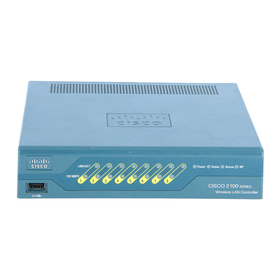
The physical port description is as follows: Up to six 10/100BASE-T cables can plug into the six back-panel data ports on the 2100 series • controller chassis. The 2100 series also has two PoE ports (ports 7 and 8). -
Page 46: Cisco 4400 Series Wireless Lan Controllers
Network Connections to Cisco Wireless LAN Controllers Cisco 4400 Series Wireless LAN Controllers Cisco 4400 series controllers can communicate with the network through one or two pairs of physical data ports, and the logical management interface can be assigned to the ports. The physical port... -
Page 47: Chapter 2 Using The Web-Browser And Cli Interfaces
This chapter describes the web-browser and CLI interfaces that you use to configure the controller. It contains these sections: Using the Web-Browser Interface, page 2-2 • Using the CLI, page 2-7 • Enabling Wireless Connections to the Web-Browser and CLI Interfaces, page 2-9 • Cisco Wireless LAN Controller Configuration Guide OL-17037-01... -
Page 48: Using The Web-Browser Interface
Note browsers supported for accessing the controller GUI and for using web authentication. You can use either the service port interface or the management interface to access the GUI. Cisco • recommends that you use the service-port interface. Refer to... -
Page 49: Using The Gui To Enable Web And Secure Web Modes
HTTP Configuration page (see Figure 2-1). If you want to download your own SSL certificate to the controller, follow the instructions in the Note “Loading an Externally Generated SSL Certificate” section on page 2-5. Cisco Wireless LAN Controller Configuration Guide OL-17037-01... -
Page 50: Using The Cli To Enable Web And Secure Web Modes
“Loading an Externally Generated SSL Certificate” section on page 2-5. (Optional) If you need to generate a new certificate, enter this command: Step 6 config certificate generate webadmin After a few seconds, the controller verifies that the certificate has been generated. Cisco Wireless LAN Controller Configuration Guide OL-17037-01... -
Page 51: Loading An Externally Generated Ssl Certificate
Also, if you load the certificate through the distribution system network port, the TFTP server can be on any subnet. A third-party TFTP server cannot run on the same computer as the Cisco WCS because the WCS • built-in TFTP server and the third-party TFTP server require the same communication port. - Page 52 Step 5 To set the password for the .PEM file so that the operating system can decrypt the web administration SSL key and certificate, enter this command: transfer download certpassword private_key_password Cisco Wireless LAN Controller Configuration Guide OL-17037-01...
-
Page 53: Using The Cli
Using the CLI The Cisco UWN Solution command line interface (CLI) is built into each controller. The CLI allows you to use a VT-100 emulator to locally or remotely configure, monitor, and control individual controllers and its associated lightweight access points. The CLI is a simple text-based, tree-structured interface that allows up to five users with Telnet-capable terminal emulators to access the controller. -
Page 54: Using A Local Serial Connection
• Use the controller IP address to Telnet to the CLI. Step 2 At the prompt, log into the CLI. The default username is admin, and the default password is admin. Step 3 Cisco Wireless LAN Controller Configuration Guide OL-17037-01... -
Page 55: Logging Out Of The Cli
Before you can open the GUI or the CLI from a wireless client device, you must configure the controller to allow the connection. Follow these steps to enable wireless connections to the GUI or CLI. Step 1 Log into the CLI. Step 2 Enter config network mgmt-via-wireless enable. Cisco Wireless LAN Controller Configuration Guide OL-17037-01... - Page 56 Step 4 To use the controller GUI to enable wireless connections, click Management > Mgmt Via Wireless page and check the Enable Controller Management to be accessible from Wireless Clients check box. Cisco Wireless LAN Controller Configuration Guide 2-10 OL-17037-01...
- Page 57 • Configuring Dynamic Interfaces, page 3-16 • Configuring Ports, page 3-19 • Enabling Link Aggregation, page 3-29 • • Configuring a 4400 Series Controller to Support More Than 48 Access Points, page 3-34 Cisco Wireless LAN Controller Configuration Guide OL-17037-01...
-
Page 58: Overview Of Ports And Interfaces
Note The controller in a Cisco Integrated Services Router and the controllers on the Cisco WiSM do not have external physical ports. They connect to the network through ports on the router or switch. Figure 3-1... - Page 59 1. The baud rate for the Gigabit Ethernet version of the controller network module is limited to 9600 bps while the baud rate for the Fast Ethernet version supports up to 57600 bps. Appendix E provides logical connectivity diagrams and related software commands for the integrated Note controllers. Cisco Wireless LAN Controller Configuration Guide OL-17037-01...
-
Page 60: Distribution System Ports
Cisco 4402 controllers have two Gigabit Ethernet distribution system ports, each of which is capable • of managing up to 48 access points. However, Cisco recommends no more than 25 access points per port due to bandwidth constraints. The 4402-25 and 4402-50 models allow a total of 25 or 50 access points to join the controller. -
Page 61: Service Port
The Cisco WiSM’s controllers use the service port for internal protocol communication between the Note controllers and the Supervisor 720. The Cisco 2100 series controllers and the controller in the Cisco Integrated Services Router do not have Note a service port. -
Page 62: Interfaces
For Cisco 4404 and WiSM controllers, configure the AP-manager interface on all distribution system ports (1, 2, 3, and 4). For Cisco 4402 controllers, configure the AP-manager interface on distribution system ports 1 and 2. In both cases, the static (or permanent) AP-manager interface is always assigned... -
Page 63: Virtual Interface
IP address, such as 1.1.1.1. The virtual interface IP address is not pingable and should not exist in any routing table in your network. In addition, the virtual interface cannot be mapped to a backup port. Cisco Wireless LAN Controller Configuration Guide OL-17037-01... -
Page 64: Service-Port Interface
Only Cisco 4400 series controllers have a service-port interface. Note You must configure an IP address on the service-port interface of both Cisco WiSM controllers. Note Otherwise, the neighbor switch is unable to check the status of each controller. -
Page 65: Wlans
3-4, each controller port connection is an 802.1Q trunk and should be configured as such on the neighbor switch. On Cisco switches, the native VLAN of an 802.1Q trunk is an untagged VLAN. Therefore, if you configure an interface to use the native VLAN on a neighboring Cisco switch, make sure you configure the interface on the controller to be untagged. -
Page 66: Configuring The Management, Ap-Manager, Virtual, And Service-Port Interfaces
This practice is extremely important for optimal performance of the controller. Cisco recommends that you assign one set of VLANs for WLANs and a different set of VLANs for Note management interfaces to ensure that controllers properly route VLAN traffic. -
Page 67: Using The Gui To Configure The Management, Ap-Manager, Virtual, And Service-Port Interfaces
NAC out-of-band integration. VLAN identifier • Enter 0 for an untagged VLAN or a non-zero value for a tagged VLAN. Cisco recommends Note using tagged VLANs for the management interface. Fixed IP address, IP netmask, and default gateway •... - Page 68 Configuring the Management, AP-Manager, Virtual, and Service-Port Interfaces AP-Manager Interface VLAN identifier • Enter 0 for an untagged VLAN or a non-zero value for a tagged VLAN. Cisco recommends Note using tagged VLANs for the AP-manager interface. Fixed IP address, IP netmask, and default gateway •...
-
Page 69: Using The Cli To Configure The Management, Ap-Manager, Virtual, And Service-Port Interfaces
Use this command to configure a quarantine VLAN on the management interface. • config interface vlan management {vlan-id | 0} Enter 0 for an untagged VLAN or a non-zero value for a tagged VLAN. Cisco recommends Note using tagged VLANs for the management interface. -
Page 70: Using The Cli To Configure The Ap-Manager Interface
• config interface vlan ap-manager {vlan-id | 0} • Enter 0 for an untagged VLAN or a non-zero value for a tagged VLAN. Cisco recommends Note using tagged VLANs for the AP-manager interface. config interface port ap-manager physical-ds-port-number •... -
Page 71: Using The Cli To Configure The Service-Port Interface
To do so, enter this command: config route add network-ip-addr ip-netmask gateway Enter save config to save your changes. Step 4 Enter show interface detailed service-port to verify that your changes have been saved. Step 5 Cisco Wireless LAN Controller Configuration Guide 3-15 OL-17037-01... -
Page 72: Configuring Dynamic Interfaces
Step 3 Enter an interface name and a VLAN identifier, as shown in Figure 3-6. Click Apply to commit your changes. The Interfaces > Edit page appears (see Figure 3-7). Step 4 Cisco Wireless LAN Controller Configuration Guide 3-16 OL-17037-01... - Page 73 To ensure proper operation, you must set the Port Number and Primary DHCP Server parameters. Click Save Configuration to save your changes. Step 6 Repeat this procedure for each dynamic interface that you want to create or edit. Step 7 Cisco Wireless LAN Controller Configuration Guide 3-17 OL-17037-01...
-
Page 74: Using The Cli To Configure Dynamic Interfaces
Enter show interface detailed operator_defined_interface_name and show interface summary to verify that your changes have been saved. Note If desired, you can enter config interface delete operator_defined_interface_name to delete a dynamic interface. Cisco Wireless LAN Controller Configuration Guide 3-18 OL-17037-01... -
Page 75: Configuring Ports
The number of parameters available on the Port > Configure page depends on your controller Note type. For instance, 2100 series controllers and the controller in a Cisco Integrated Services Router have fewer configurable parameters than a 4400 series controller, which is shown in Figure 3-9. - Page 76 1000 Mbps full duplex Controller network module 100 Mbps full duplex Catalyst 3750G Integrated Wireless 1000 Mbps full duplex LAN Controller Switch Link Status The port’s link status. Values: Link Up or Link Down Cisco Wireless LAN Controller Configuration Guide 3-20 OL-17037-01...
- Page 77 Determines if the connecting device is equipped to receive power through the Ethernet cable and if so provides -48 VDC. Values: Enable or Disable Some older Cisco access points do not draw PoE even if it is Note enabled on the controller port. In such cases, contact the Cisco Technical Assistance Center (TAC).
-
Page 78: Configuring Port Mirroring
Also, a controller’s service port cannot be used as a mirrored port. Port mirroring is not supported when link aggregation (LAG) is enabled on the controller. Note Cisco recommends that you do not mirror traffic from one controller port to another as this setup could Note cause network problems. -
Page 79: Configuring Spanning Tree Protocol
STP forces redundant data paths into a standby (blocked) state. If a network segment in the spanning tree fails and a redundant path exists, the spanning-tree algorithm recalculates the spanning-tree topology and activates the standby path. Cisco Wireless LAN Controller Configuration Guide 3-23 OL-17037-01... -
Page 80: Using The Gui To Configure Spanning Tree Protocol
The port prepares to participate in frame forwarding. Forwarding The port forwards frames. Broken The port is malfunctioning. STP Port Designated Root The unique identifier of the root bridge in the configuration BPDUs. Cisco Wireless LAN Controller Configuration Guide 3-24 OL-17037-01... - Page 81 Determines whether the STP port path cost is set automatically or specified by the user. If you choose User Configured, you also need to set a value for the STP Port Path Cost parameter. Range: Auto or User Configured Default: Auto Cisco Wireless LAN Controller Configuration Guide 3-25 OL-17037-01...
- Page 82 This page allows you to enable or disable the spanning tree algorithm for the controller, modify its characteristics, and view the STP status.Table 3-6 interprets the current STP status for the controller. Cisco Wireless LAN Controller Configuration Guide 3-26 OL-17037-01...
- Page 83 At most, one configuration BPDU can be transmitted in any hold time period. Step 9 Table 3-7 lists and describes the controller’s configurable STP parameters. Follow the instructions in the table to make any desired changes. Cisco Wireless LAN Controller Configuration Guide 3-27 OL-17037-01...
-
Page 84: Using The Cli To Configure Spanning Tree Protocol
Enter one of these commands to configure the STP port administrative mode: • config spanningtree port mode 802.1d {port-number | all} • config spanningtree port mode fast {port-number | all} config spanningtree port mode off {port-number | all} • Cisco Wireless LAN Controller Configuration Guide 3-28 OL-17037-01... -
Page 85: Enabling Link Aggregation
With LAG enabled, a 4402 controller’s logical port supports up to 50 access points, a 4404 controller’s logical port supports up to 100 access points, and the logical port on each Cisco WiSM controller supports up to 150 access points. - Page 86 When configuring bundled ports on the controller, you may want to consider terminating on two different modules within a modular switch such as the Catalyst 6500; however, Cisco does not recommend connecting the LAG ports of a 4400 controller to multiple Catalyst 6500 or 3750G switches.
- Page 87 LAG. From the 12.2(33)SXH and later releases, Catalyst 6500 IOS software offers the exclude vlan keyword to the port-channel load-balance command to implement src-dst-ip load distribution. See the Cisco IOS Interface and Hardware Component Command Reference guide for more information.
-
Page 88: Link Aggregation Guidelines
When you enable LAG, all ports participate in LAG by default. Therefore, you must configure LAG • for all of the connected ports in the neighbor switch. When you enable LAG on the Cisco WiSM, you must enable port-channeling/Ether-channeling for • all of the controller’s ports on the switch. -
Page 89: Using The Gui To Enable Link Aggregation
Set the LAG Mode on Next Reboot parameter to Enabled. Step 2 Choose Disabled if you want to disable LAG. LAG is disabled by default on the Cisco 4400 Note series controllers but enabled by default on the Cisco WiSM. -
Page 90: Using The Cli To Enable Link Aggregation
As noted earlier, 4400 series controllers can support up to 48 access points per port. However, you can configure your 4400 series controller to support more access points using one of the following methods: Link aggregation, page 3-35 • Multiple AP-manager interfaces, page 3-35 • Cisco Wireless LAN Controller Configuration Guide 3-34 OL-17037-01... -
Page 91: Using Link Aggregation
“Enabling Link Aggregation” section on page 3-29 for more information and instructions on enabling link aggregation. Link aggregation is the only method that can be used for the Cisco WiSM and Catalyst 3750G Integrated Note Wireless LAN Controller Switch controllers. - Page 92 The controller no longer includes the failed AP-manager interface in the CAPWAP or LWAPP discovery responses. The access points then rejoin the controller and are load-balanced among the available AP-manager interfaces. Cisco Wireless LAN Controller Configuration Guide 3-36 OL-17037-01...
- Page 93 Configuring Ports and Interfaces Configuring a 4400 Series Controller to Support More Than 48 Access Points Figure 3-15 Three AP-Manager Interfaces Figure 3-16 illustrates the use of four AP-manager interfaces to support 100 access points. Cisco Wireless LAN Controller Configuration Guide 3-37 OL-17037-01...
- Page 94 Interfaces > New Page Step 3 Enter an AP-manager interface name and a VLAN identifier, as shown above. Click Apply to commit your changes. The Interfaces > Edit page appears (see Figure 3-18). Step 4 Cisco Wireless LAN Controller Configuration Guide 3-38 OL-17037-01...
- Page 95 To make the interface an AP-manager interface, check the Enable Dynamic AP Management check Step 6 box. Click Save Configuration to save your settings. Step 7 Repeat this procedure for each additional AP-manager interface that you want to create. Step 8 Cisco Wireless LAN Controller Configuration Guide 3-39 OL-17037-01...
- Page 96 Chapter 3 Configuring Ports and Interfaces Configuring a 4400 Series Controller to Support More Than 48 Access Points Cisco Wireless LAN Controller Configuration Guide 3-40 OL-17037-01...
- Page 97 Configuring Quality of Service, page 4-45 • Configuring Voice and Video Parameters, page 4-52 • Configuring EDCA Parameters, page 4-67 • Configuring Cisco Discovery Protocol, page 4-69 • Configuring RFID Tag Tracking, page 4-79 • Configuring and Viewing Location Settings, page 4-84 •...
-
Page 98: Configuring Controller Settingswireless Device Access
NTP server settings (the wizard prompts you for NTP server settings when you run the wizard on a • wireless controller network module installed in a Cisco Integrated Services router) Other port and parameter settings: service port, Radio Resource Management (RRM), third-party •... -
Page 99: Resetting The Device To Default Settings
When you are prompted for a username, enter recover-config to restore the factory default configuration. The controller reboots and displays this message: Welcome to the Cisco WLAN Solution Wizard Configuration Tool Use the configuration wizard to enter configuration settings. Step 3 Resetting to Default Settings Using the GUI Follow these steps to return to default settings using the GUI. -
Page 100: Running The Configuration Wizard On The Cli
CLI. Note To configure the controller in the Catalyst 3750G Integrated Wireless LAN Controller Switch, Cisco recommends that you use the GUI configuration wizard that launches from the 3750 Device Manager. Refer to the Catalyst 3750G Integrated Wireless LAN Controller Switch Getting Started Guide for instructions. - Page 101 US,CA,MX). After the configuration wizard runs, you need to assign each access point joined to the controller to a specific country. See the “Configuring Country Codes” section on page 7-49 for instructions. Cisco Wireless LAN Controller Configuration Guide OL-17037-01...
-
Page 102: Using The Autoinstall Feature For Controllers Without A Configuration
Configuring Controller SettingsWireless Device Access Using the AutoInstall Feature for Controllers Without a Configuration When you run the wizard on a wireless controller network module installed in a Cisco Integrated Step 24 Services Router, the wizard prompts you for NTP server settings. The controller network module does not have a battery and cannot save a time setting. -
Page 103: Server
– address of the TFTP server. AutoInstall performs a DNS lookup on the default TFTP server name (cisco-wlc-tftp). If the – DNS lookup is successful, the IP address that is received is used as the IP address of the TFTP server. -
Page 104: Selecting A Configuration File
Note For more information on configuring DHCP and TFTP servers through WCS, see Chapter 10 of the Cisco Wireless Control System Configuration Guide, Release 5.2. Selecting a Configuration File After the host name and TFTP server have been determined, AutoInstall attempts to download a configuration file. -
Page 105: Example Of Autoinstall Operation
After the controller is discovered, WCS pushes the templates that are defined in the configuration group. For more information about the AutoInstall feature and WCS, see Chapter 15 of the Cisco Wireless Control System Configuration Guide, Release 5.2. -
Page 106: Managing The System Date And Time
Using the controller GUI, follow these steps to configure the local date and time. Click Commands > Set Time to open the Set Time page (see Figure 4-1). Step 1 Figure 4-1 Set Time Page Cisco Wireless LAN Controller Configuration Guide 4-10 OL-17037-01... -
Page 107: Using The Cli To Configure The Date And Time
When setting the time, the current local time is entered in terms of GMT and as a value between Note 00:00 and 24:00. For example, if it is 8:00 a.m. Pacific time in the United States, you would enter 16:00 because the Pacific time zone is 8 hours behind GMT. Cisco Wireless LAN Controller Configuration Guide 4-11 OL-17037-01... - Page 108 26. (GMT +9:00) Tokyo, Osaka, Sapporo – 27. (GMT +9:30) Darwin – 28. (GMT+10:00) Sydney, Melbourne, Canberra – 29. (GMT+11:00) Magadan, Solomon Is., New Caledonia – 30. (GMT+12:00) Kamchatka, Marshall Is., Fiji – Cisco Wireless LAN Controller Configuration Guide 4-12 OL-17037-01...
- Page 109 If you configured the time zone location, the Timezone Delta value is set to “0:0.” If you manually configured the time zone using the time zone delta, the Timezone Location is blank. Cisco Wireless LAN Controller Configuration Guide 4-13 OL-17037-01...
-
Page 110: Configuring 802.11 Bands
To specify the size at which packets are fragmented, enter a value between 256 and 2346 bytes Step 5 (inclusive) in the Fragmentation Threshold field. Enter a low number for areas where communication is poor or where there is a great deal of radio interference. Cisco Wireless LAN Controller Configuration Guide 4-14 OL-17037-01... -
Page 111: Using The Cli To Configure 802.11 Bands
Japan could rely on DTPC to adjust its channel and power settings automatically when it travels to Italy and joins a network there. On access points that run Cisco IOS software, this feature is called world mode. Note... - Page 112 Japan could rely on DTPC to adjust its channel and power settings automatically when it travels to Italy and joins a network there. On access points that run Cisco IOS software, this feature is called world mode. Note...
-
Page 113: Configuring 802.11N Parameters
Fragmentation Threshold....... 2346 Configuring 802.11n Parameters This section provides instructions for managing 802.11n devices such as the Cisco Aironet 1140 and 1250 Series Access Points on your network. The 802.11n devices support the 2.4- and 5-GHz bands and offer high-throughput data rates. - Page 114 5 (58 Mbps) • 6 (65 Mbps) • 7 (72 Mbps) • 8 (14 Mbps) • 9 (29 Mbps) • 10 (43 Mbps) • 11 (58 Mbps) • 12 (87 Mbps) • Cisco Wireless LAN Controller Configuration Guide 4-18 OL-17037-01...
-
Page 115: Using The Cli To Configure 802.11N Parameters
To determine if an access point supports 802.11n, look at the 11n Supported field on either the Note 802.11a/n (or 802.11b/g/n) Cisco APs > Configure page or the 802.11a/n (or 802.11b/g/n) AP Interfaces > Details page. Using the CLI to Configure 802.11n Parameters Using the controller CLI, follow these steps to configure 802.11n parameters. -
Page 116: Step 10 To Save Your Changes, Enter This Command
802.11a Network....... Enabled 11nSupport........Enabled 802.11a Low Band......Enabled 802.11a Mid Band......Enabled 802.11a High Band......Enabled 802.11a Operational Rates 802.11a 6M Rate......Mandatory 802.11a 9M Rate......Supported 802.11a 12M Rate......Mandatory Cisco Wireless LAN Controller Configuration Guide 4-20 OL-17037-01... - Page 117 Voice AC - Admission control (ACM).... Enabled Voice max RF bandwidth......75 Voice reserved roaming bandwidth....6 Voice load-based CAC mode..... Disabled Voice tspec inactivity timeout....Disabled Video AC - Admission control (ACM).... Enabled Cisco Wireless LAN Controller Configuration Guide 4-21 OL-17037-01...
-
Page 118: Configuring Dhcp Proxy
CAPWAP tunnel toward the client. As a result, the internal DHCP server cannot be used when DHCP proxy is disabled. The ability to disable DHCP proxy allows organizations to use DHCP servers that do not support Cisco’s native proxy mode of operation. It should be disabled only when required by the existing infrastructure. -
Page 119: Using The Cli To Configure Dhcp Proxy
Usernames and passwords are case-sensitive and can contain up to 24 ASCII characters. Usernames and passwords cannot contain spaces. If you ever need to change the password for an existing username, enter this command: Note config mgmtuser password username new_password Cisco Wireless LAN Controller Configuration Guide 4-23 OL-17037-01... -
Page 120: Restoring Passwords
When the Password prompt appears, enter your new password. The controller logs you in with your new username and password. Configuring SNMP Cisco recommends that you use the GUI to configure SNMP settings on the controller. To use the CLI, follow these steps: Enter config snmp community create name to create an SNMP community name. -
Page 121: Changing The Default Values Of Snmp Community Strings
The controller has commonly known default values of “public” and “private” for the read-only and read-write SNMP community strings. Using these standard values presents a security risk. Therefore, Cisco strongly advises that you change these values. Using the GUI to Change the SNMP Community String Default Values Follow these steps to change the SNMP community string default values through the controller GUI. - Page 122 Step 8 Click Save Configuration to save your settings. Step 9 Repeat this procedure if a “public” or “private” community still appears on the SNMP v1 / v2c Step 10 Community page. Cisco Wireless LAN Controller Configuration Guide 4-26 OL-17037-01...
-
Page 123: Using The Cli To Change The Snmp Community String Default Values
Changing the Default Values for SNMP v3 Users The controller uses a default value of “default” for the username, authentication password, and privacy password for SNMP v3 users. Using these standard values presents a security risk. Therefore, Cisco strongly advises that you change these values. - Page 124 HMAC-MD5 or HMAC-SHA as the authentication protocol in Step In the Priv Password and Confirm Priv Password fields, enter the shared secret key to be used for Step 9 encryption. You must enter at least 12 characters. Cisco Wireless LAN Controller Configuration Guide 4-28 OL-17037-01...
-
Page 125: Using The Cli To Change The Snmp V3 User Default Values
For example, if load balancing is enabled and the client count is configured as 5 clients, when a sixth client tries to associate to the access point, the client receives an 802.11 response packet with status code 17, indicating that the access point is busy. Cisco Wireless LAN Controller Configuration Guide 4-29 OL-17037-01... -
Page 126: Using The Gui To Configure Aggressive Load Balancing
Configuring Controller SettingsWireless Device Access Configuring Aggressive Load Balancing When you use Cisco 7921 and 7920 Wireless IP Phones with controllers, make sure that aggressive load Note balancing is disabled for each controller. Otherwise, the initial roam attempt by the phone may fail, causing a disruption in the audio path. -
Page 127: Configuring Fast Ssid Changing
{enable | disable} To save your changes, enter this command: Step 2 save config Enabling 802.3X Flow Control 802.3X Flow Control is disabled by default. To enable it, enter config switchconfig flowcontrol enable. Cisco Wireless LAN Controller Configuration Guide 4-31 OL-17037-01... -
Page 128: Configuring 802.3 Bridging
Note In controller software release 5.2, the software-based forwarding architecture for 2100-series-based controllers is being replaced with a new forwarding plane architecture. As a result, 2100 series controllers and the Cisco Wireless LAN Controller Network Module for Cisco Integrated Services Routers bridge 802.3 packets by default. -
Page 129: Using The Cli To Configure 802.3 Bridging
Disabled to disable this feature. The default value is Disabled. Note In controller software release 5.2, you can disable 802.3 bridging only for 4400 series controllers, the Cisco WiSM, and the Catalyst 3750G Wireless LAN Controller Switch. Click Apply to commit your changes. Step 3 Step 4 Click Save Configuration to save your changes. -
Page 130: Configuring Multicast Mode
The IGMP packets from clients are forwarded to the router. As a result, the router IGMP table is • updated with the IP address of the clients as the last reporter. Cisco Wireless LAN Controller Configuration Guide 4-34 OL-17037-01... -
Page 131: Guidelines For Using Multicast Mode
Access points subscribe to the CAPWAP multicast group using IGMP. • Cisco 1100, 1130, 1200, 1230, and 1240 access points use IGMP versions 1, 2, and 3. • Access points in monitor mode, sniffer mode, or rogue detector mode do not join the CAPWAP multicast group address. -
Page 132: Using The Gui To Enable Multicast Mode
Therefore, you may want to consider not using these port numbers with the multicast applications on your network. Cisco recommends that any multicast applications on your network not use the multicast address • configured as the CAPWAP multicast group address on the controller. -
Page 133: Using The Gui To View Multicast Groups
This page shows all the multicast groups and their corresponding MGIDs. Click the link for a specific MGID (such as MGID 550) to see a list of all the clients joined to the Step 2 multicast group in that particular MGID. Cisco Wireless LAN Controller Configuration Guide 4-37 OL-17037-01... -
Page 134: Using The Cli To Enable Multicast Mode
The controller always generates a general IGMP query (that is, to destination address 224.0.0.1) and sends it on all WLANs with an MGID value of 1. Step 5 To save your changes, enter this command: save config Cisco Wireless LAN Controller Configuration Guide 4-38 OL-17037-01... -
Page 135: Using The Cli To View Multicast Groups
To see all of the clients per MGID on the access point and the number of clients per WLAN, enter this Step 3 command: debug ap command “show capwap mcast mgid id mgid_value” Cisco_AP Cisco Wireless LAN Controller Configuration Guide 4-39 OL-17037-01... -
Page 136: Configuring Client Roaming
20-millisecond or shorter latency time for the roaming handover is easily met by the Cisco UWN Solution, which has an average handover latency of 5 or fewer milliseconds when open authentication is used. This short latency period is controlled by controllers rather than allowing independent access points to negotiate roaming handovers. -
Page 137: Ccx Layer 2 Client Roaming
The access point provides its associated client information about its neighbors using a neighbor-list update unicast message. Enhanced neighbor list request (E2E)—The End-2-End specification is a Cisco and Intel joint • program that defines new protocols and interfaces to improve the overall voice and roaming experience. -
Page 138: Using The Gui To Configure Ccx Client Roaming Parameters
For example, the client can scan slowly when the RSSI is above the threshold and scan more rapidly when below the threshold. Range: –70 to –77 dBm Default: –72 dBm Cisco Wireless LAN Controller Configuration Guide 4-42 OL-17037-01... -
Page 139: Using The Cli To Configure Ccx Client Roaming Parameters
The number of neighbor list reports sent – The number of broadcast neighbor updates sent – To view the roaming history for a particular client, enter this command: show client roam-history client_mac Cisco Wireless LAN Controller Configuration Guide 4-43 OL-17037-01... -
Page 140: Using The Cli To Debug Ccx Client Roaming Issues
The default value is enabled. You might want to disable this binding check if you have a routed network behind a workgroup Note bridge (WGB). To save your changes, enter this command: Step 2 save config Cisco Wireless LAN Controller Configuration Guide 4-44 OL-17037-01... -
Page 141: Configuring Quality Of Service
Click Wireless > QoS > Profiles to open the QoS Profiles page. Step 2 Click the name of the profile that you want to configure to open the Edit QoS Profile page (see Step 3 Figure 4-14). Cisco Wireless LAN Controller Configuration Guide 4-45 OL-17037-01... - Page 142 50% of the available RF bandwidth. Actual throughput could be less than 50%, but it will never be more than 50%. In the Queue Depth field, enter the maximum number of packets that access points keep in their queues. Step 10 Any additional packets are dropped. Cisco Wireless LAN Controller Configuration Guide 4-46 OL-17037-01...
-
Page 143: Using The Cli To Configure Qos Profiles
{bronze | silver | gold | platinum} usage_percentage Step 8 To specify the maximum number of packets that access points keep in their queues, enter this command: config qos queue_length {bronze | silver | gold | platinum} queue_length Cisco Wireless LAN Controller Configuration Guide 4-47 OL-17037-01... -
Page 144: Configuring Quality Of Service Roles
Using the GUI to Configure QoS Roles Follow these steps to configure QoS roles using the controller GUI. Click Wireless > QoS > Roles to open the QoS Roles for Guest Users page (see Figure 4-15). Step 1 Cisco Wireless LAN Controller Configuration Guide 4-48 OL-17037-01... - Page 145 To define the average data rate for TCP traffic on a per user basis, enter the rate in Kbps in the Average Step 6 Data Rate field. You can enter a value between 0 and 60,000 Kbps (inclusive). A value of 0 imposes no bandwidth restriction on the QoS role. Cisco Wireless LAN Controller Configuration Guide 4-49 OL-17037-01...
-
Page 146: Using The Cli To Configure Qos Roles
QoS policy may block traffic to and from the wireless client. config netuser guest-role qos data-rate average-realtime-rate role_name rate—Configures the • average real-time rate for UDP traffic on a per user basis. Cisco Wireless LAN Controller Configuration Guide 4-50 OL-17037-01... - Page 147 Average Data Rate......10 Burst Data Rate......10 Average Realtime Rate....... 100 Burst Realtime Rate......100 Role Name........Vendor Average Data Rate......unconfigured Burst Data Rate......unconfigured Average Realtime Rate....... unconfigured Burst Realtime Rate...... unconfigured Cisco Wireless LAN Controller Configuration Guide 4-51 OL-17037-01...
-
Page 148: Configuring Voice And Video Parameters
• Unscheduled automatic power save delivery • Each of these parameters is supported in Cisco Compatible Extensions (CCX) v4 and v5. See the “Configuring Cisco Client Extensions” section on page 6-39 for more information on CCX. CCX is not supported on the AP1030. -
Page 149: Expedited Bandwidth Requests
When video ACM is enabled, the controller rejects a video TSPEC if the Nom-MSDU size in the TSPEC Note is greater than 149 or the mean data rate is greater than 1 Kb/s. Cisco Wireless LAN Controller Configuration Guide 4-53 OL-17037-01... -
Page 150: U-Apsd
Step 3 the 802.11a (or 802.11b/g) Network Status check box, and click Apply. Click Voice under 802.11a/n or 802.11b/g/n. The 802.11a (or 802.11b) > Voice Parameters page appears Step 4 (see Figure 4-17). Cisco Wireless LAN Controller Configuration Guide 4-54 OL-17037-01... - Page 151 802.11b/g) Network Status check box, and click Apply. Click Save Configuration to save your changes. Step 14 Repeat this procedure if you want to configure voice parameters for another radio band (802.11a or Step 15 802.11b/g). Cisco Wireless LAN Controller Configuration Guide 4-55 OL-17037-01...
-
Page 152: Using The Gui To Configure Video Parameters
Re-enable all WMM WLANs and click Apply. Step 9 Step 10 To re-enable the radio network, click Network under 802.11a/n or 802.11b/g/n, check the 802.11a (or 802.11b/g) Network Status check box, and click Apply. Cisco Wireless LAN Controller Configuration Guide 4-56 OL-17037-01... -
Page 153: Using The Gui To View Voice And Video Settings
Click Monitor > Clients to open the Clients page (see Figure 4-19). Step 1 Figure 4-19 Clients Page Click the MAC address of the desired client to open the Clients > Detail page (see Figure 4-20). Step 2 Cisco Wireless LAN Controller Configuration Guide 4-57 OL-17037-01... - Page 154 Figure 4-20 Clients > Detail Page This page shows the U-APSD status (if enabled) for this client under Quality of Service Properties. Click Back to return to the Clients page. Step 3 Cisco Wireless LAN Controller Configuration Guide 4-58 OL-17037-01...
- Page 155 Click the Detail link for the desired access point to open the Clients > AP > Traffic Stream Metrics page (see Figure 4-22). Figure 4-22 Clients > AP > Traffic Stream Metrics Page Cisco Wireless LAN Controller Configuration Guide 4-59 OL-17037-01...
- Page 156 Figure 4-23 802.11a/n Radios Page Hover your cursor over the blue drop-down arrow for the desired access point and choose 802.11aTSM or 802.11b/gTSM. The AP > Clients page appears (see Figure 4-24). Cisco Wireless LAN Controller Configuration Guide 4-60 OL-17037-01...
- Page 157 Click the Detail link for the desired client to open the AP > Clients > Traffic Stream Metrics page (see Figure 4-25). Figure 4-25 AP > Clients > Traffic Stream Metrics Page Cisco Wireless LAN Controller Configuration Guide 4-61 OL-17037-01...
-
Page 158: Using The Cli To Configure Voice Parameters
{802.11a | 802.11b} cac voice tspec-inactivity-timeout {enable | ignore} To enable or disable load-based CAC for the 802.11a or 802.11b/g network, enter this command: Step 10 config {802.11a | 802.11b} cac voice load-based {enable | disable} Cisco Wireless LAN Controller Configuration Guide 4-62 OL-17037-01... -
Page 159: Using The Cli To Configure Video Parameters
To save your settings, enter this command: Step 5 save config To enable or disable video CAC for the 802.11a or 802.11b/g network, enter this command: Step 6 config {802.11a | 802.11b} cac video acm {enable | disable} Cisco Wireless LAN Controller Configuration Guide 4-63 OL-17037-01... -
Page 160: Using The Cli To View Voice And Video Settings
Total num of voice calls in progress... 0 Num of roaming voice calls in progress..0 Total Num of voice calls since AP joined..0 Total Num of roaming calls since AP joined..0 Cisco Wireless LAN Controller Configuration Guide 4-64 OL-17037-01... - Page 161 Total packet lost count (5sec)......10 Maximum Lost Packet count(5sec)......5 Average Lost Packet count(5secs)......2 The statistics are shown in 90-second intervals. The timestamp field shows the specific Note interval when the statistics were collected. Cisco Wireless LAN Controller Configuration Guide 4-65 OL-17037-01...
- Page 162 {all | event | packet}{enable | disable} where all configures debugging for all CAC messages, event configures debugging for all CAC events, and packet configures debugging for all CAC packets. Cisco Wireless LAN Controller Configuration Guide 4-66 OL-17037-01...
-
Page 163: Configuring Edca Parameters
Voice & Video Optimized—Enables EDCA voice- and video-optimized profile parameters. Choose this option when both voice and video services are deployed on your network. If you deploy video services, admission control (ACM) must be disabled. Note Cisco Wireless LAN Controller Configuration Guide 4-67 OL-17037-01... -
Page 164: Using The Cli To Configure Edca Parameters
? is one of the following: • wmm-default • svp-voice • optimized-voice • optimized-video-voice Refer to the “Using the GUI to Configure EDCA Parameters” section above for a description of Note each option. Cisco Wireless LAN Controller Configuration Guide 4-68 OL-17037-01... -
Page 165: Configuring Cisco Discovery Protocol
CDPv1 and CDPv2 are supported on the following devices: 2100 and 4400 series controllers • CDP is not supported on the controllers that are integrated into Cisco switches and routers, Note including those in the Catalyst 3750G Integrated Wireless LAN Controller Switch, the Cisco WiSM, and the Cisco 28/37/38xx Series Integrated Services Router. - Page 166 Chapter 4 Configuring Controller SettingsWireless Device Access Configuring Cisco Discovery Protocol An access point connected directly to a 2100 series controller • This support enables network management applications to discover Cisco devices. These TLVs are supported by both the controller and the access point: Device-ID TLV: 0x0001—The host name of the controller, the access point, or the CDP neighbor.
- Page 167 Power Consumption TLV: 0x0010—The maximum amount of power consumed by the access • point. This TLV is not supported on access points that are connected directly to a 2100 series controller. You can configure CDP and view CDP information using the GUI in controller software release 4.1 or later or the CLI in controller software release 4.0 or later.
-
Page 168: Using The Gui To Configure Cisco Discovery Protocol
Configuring Controller SettingsWireless Device Access Configuring Cisco Discovery Protocol Using the GUI to Configure Cisco Discovery Protocol Follow these steps to configure CDP using the controller GUI. Click Controller > CDP > Global Configuration to open the CDP > Global Configuration page (see... -
Page 169: Using The Gui To View Cisco Discovery Protocol Information
Figure 4-29 All APs > Details for (Advanced) Page Check the Cisco Discovery Protocol check box to enable CDP on this access point or uncheck it to disable this feature. The default value is enabled. Click Apply to commit your changes. - Page 170 To see more detailed information about each interface’s CDP neighbor, click the name of the desired Step 2 interface neighbor. The CDP > Interface Neighbors > Detail page appears (see Figure 4-31). Figure 4-31 CDP > Interface Neighbors > Detail Page Cisco Wireless LAN Controller Configuration Guide 4-74 OL-17037-01...
- Page 171 To see a list of CDP neighbors for a specific access point, click the CDP Neighbors link for the desired access point. The CDP > AP Neighbors page appears (see Figure 4-34). Figure 4-33 CDP > AP Neighbors Page Cisco Wireless LAN Controller Configuration Guide 4-75 OL-17037-01...
- Page 172 The hardware platform of the CDP neighbor device • The software running on the CDP neighbor • To see CDP traffic information, click Traffic Metrics. The CDP > Traffic Metrics page appears (see Step 6 Figure 4-35). Cisco Wireless LAN Controller Configuration Guide 4-76 OL-17037-01...
-
Page 173: Using The Cli To Configure Cisco Discovery Protocol
• The number of invalid packets • Using the CLI to Configure Cisco Discovery Protocol Use these commands to configure CDP using the controller CLI. To enable or disable CDP on the controller, enter this command: config cdp {enable | disable} CDP is enabled by default. -
Page 174: Using The Cli To View Cisco Discovery Protocol Information
To save your settings, enter this command: save config Using the CLI to View Cisco Discovery Protocol Information Use these commands to obtain information about CDP neighbors on the controller. To see the status of CDP and to view CDP protocol information, enter this command:... -
Page 175: Configuring Rfid Tag Tracking
The controller supports tags from AeroScout, WhereNet, and Pango (an InnerWireless company). Some of the tags from these vendors comply with Cisco Compatible Extensions for RFID Tags. See Table 4-3 for details. The location appliance receives telemetry and chokepoint information from tags that are compliant with this CCX specification. - Page 176 NMSP to function properly, the TCP port (16113) over which the controller and location appliance communicate must be open (not blocked) on any firewall that exists between these two devices. Refer to the Cisco Location Appliance Configuration Guide for additional information on NMSP and RFID tags.
-
Page 177: Using The Cli To Configure Rfid Tag Tracking
The static timeout value is the amount of time that the controller maintains tags before expiring them. For example, if a tag is configured to beacon every 30 seconds, Cisco recommends that you set the timeout value to 90 seconds (approximately three times the beacon value). The default value is 1200 seconds. -
Page 178: Using The Cli To View Rfid Tag Tracking Information
08 05 07 a8 02 00 10 00 23 b2 4e 03 02 0a 03 Nearby AP Statistics: lap1242-2(slot 0, chan 1) 50 seconds ag..-76 dBm lap1242(slot 0, chan 1) 50 seconds ago..-65 dBm Cisco Wireless LAN Controller Configuration Guide 4-82 OL-17037-01... -
Page 179: Using The Cli To Debug Rfid Tag Tracking Issues
To configure MAC address debugging, enter this command: • debug mac addr mac_address Cisco recommends that you perform the debugging on a per-tag basis. If you enable Note debugging for all of the tags, the console or Telnet screen is inundated with messages. -
Page 180: Configuring And Viewing Location Settings
Thu Oct 11 08:52:26 2007: sshpmGetIssuerHandles: Key Data 5c0917f1 ec1d5061 2d386351 573f2c5e Thu Oct 11 08:52:30 2007: sshpmGetIssuerHandles: Key Data b9020301 0001 Thu Oct 11 08:52:30 2007: sshpmGetIssuerHandles: SSC Key Hash is 4869b32638c00ffca88abe9b1a8e0525b9344b8b Cisco Wireless LAN Controller Configuration Guide 4-84 OL-17037-01... -
Page 181: Modifying The Nmsp Notification Interval For Clients, Rfid Tags, And Rogues
1 and 30 seconds: • config nmsp notify-interval measurement clients interval • config nmsp notify-interval measurement rfid interval • config nmsp notify-interval measurement rogues interval Cisco Wireless LAN Controller Configuration Guide 4-85 OL-17037-01... -
Page 182: Synchronizing The Controller And Location Appliance
For controller software release 4.2 or later, if a location appliance (release 3.1 or later) is installed on your network, the time zone must be set on the controller to ensure proper synchronization between the two systems. Also, Cisco highly recommends that the time be set for networks that do not have location appliances. Refer to the “Managing the System Date and Time”... - Page 183 S69 Capability........Supported Mirroring........Disabled QoS Level........Silver See the Cisco Wireless Control System Configuration Guide or the Cisco Location Appliance Note Configuration Guide for instructions on enabling location presence on a location appliance. Cisco Wireless LAN Controller Configuration Guide...
- Page 184 Connection status: UP Freed Connection: Nmsp Subscr Req: NMSP Subscr Resp: Info Req: Info Resp: Measure Req: Measure Resp: Stats Req: Stats Resp: Info Notify: Measure Notify: Loc Capability: Location Req: Location Rsp: Cisco Wireless LAN Controller Configuration Guide 4-88 OL-17037-01...
-
Page 185: Configuring The Supervisor 720 To Support The Wism
Configuring the Supervisor 720 to Support the WiSM When you install a WiSM in a Cisco Catalyst 6500 switch or a Cisco 7600 series router, you must configure the Supervisor 720 to support the WiSM. When the supervisor detects the WiSM, the supervisor creates ten Gigabit Ethernet interfaces, ranging from Gigslot/1 to Gigslot/8. -
Page 186: General Wism Guidelines
Assign an IP address and gateway to the VLAN. Step 10 Return to global config mode. Step 11 wism service-vlan vlan Configure the VLAN that you created in steps 8 through 10 to communicate with the WiSM service ports. Cisco Wireless LAN Controller Configuration Guide 4-90 OL-17037-01... -
Page 187: Using The Wireless Lan Controller Network Module
NTP server when it powers up. When you install the module, the configuration wizard prompts you for NTP server information. To access the CNM bootloader, Cisco recommends that you reset the CNM from the router. If you •... - Page 188 Chapter 4 Configuring Controller SettingsWireless Device Access Using the Wireless LAN Controller Network Module Cisco Wireless LAN Controller Configuration Guide 4-92 OL-17037-01...
- Page 189 C H A P T E R Configuring Security Solutions This chapter describes security solutions for wireless LANs. It contains these sections: Cisco UWN Solution Security, page 5-2 • Configuring RADIUS, page 5-3 • • Configuring TACACS+, page 5-18 •...
-
Page 190: Cisco Uwn Solution Security
• Security Overview The Cisco UWN security solution bundles potentially complicated Layer 1, Layer 2, and Layer 3 802.11 Access Point security components into a simple policy manager that customizes system-wide security policies on a per-WLAN basis. The Cisco UWN security solution provides simple, unified, and systematic security management tools. -
Page 191: Layer 3 Solutions
The WEP problem can be further solved using industry-standard Layer 3 security solutions such as passthrough VPNs (virtual private networks). The Cisco UWN Solution supports local and RADIUS MAC (media access control) filtering. This filtering is best suited to smaller client groups with a known list of 802.11 access card MAC addresses. -
Page 192: Configuring Radius On The Acs
Click Network Configuration on the ACS main page. Step 1 Step 2 Click Add Entry under AAA Clients to add your controller to the server. The Add AAA Client page appears (see Figure 5-1). Cisco Wireless LAN Controller Configuration Guide OL-17037-01... - Page 193 The shared secret key must be the same on both the server and the controller. Note Choose RADIUS (Cisco Aironet) from the Authenticate Using drop-down box. Step 6 Click Submit + Apply to save your changes. Step 7 Click Interface Configuration on the ACS main page.
-
Page 194: Using The Gui To Configure Radius
Click Edit Settings. The Group Setup page appears. Step 17 Under Cisco Aironet Attributes, check the Cisco-Aironet-Session-Timeout check box and enter a Step 18 session timeout value in the edit box. Step 19... - Page 195 To edit an existing RADIUS server, click the server index number for that server. The RADIUS • Authentication (or Accounting) Servers > Edit page appears. To add a RADIUS server, click New. The RADIUS Authentication (or Accounting) Servers > New • page appears (see Figure 5-3). Cisco Wireless LAN Controller Configuration Guide OL-17037-01...
- Page 196 If you are adding a new server, enter the RADIUS server’s UDP port number for the interface protocols Step 12 in the Port Number field. The valid range is 1 to 65535, and the default value is 1812 for authentication and 1813 for accounting. Cisco Wireless LAN Controller Configuration Guide OL-17037-01...
- Page 197 30 seconds, and the default value is 2 seconds. Note Cisco recommends that you increase the timeout value if you experience repeated reauthentication attempts or the controller falls back to the backup server when the primary server is active and reachable.
- Page 198 If you enabled Active fallback mode in Step b, enter the name to be sent in the inactive server probes. in the Username field. You can enter up to 16 alphanumeric characters. The default value is “cisco-probe.” Cisco Wireless LAN Controller Configuration Guide 5-10 OL-17037-01...
-
Page 199: Using The Cli To Configure Radius
{enable | disable}—Enables AES key wrap, which makes the shared secret between the controller and the RADIUS server more secure. AES key wrap is designed for Federal Information Processing Standards (FIPS) customers and requires a key-wrap compliant RADIUS authentication server. Cisco Wireless LAN Controller Configuration Guide 5-11 OL-17037-01... - Page 200 If you did not configure a RADIUS server entry on the WLAN, you must enable this option for network users. config radius acct ipsec {enable | disable} index—Enables or disables the IP security mechanism. • Cisco Wireless LAN Controller Configuration Guide 5-12 OL-17037-01...
- Page 201 2........radius Use these commands to see RADIUS statistics: Step 8 show radius summary—Shows a summary of RADIUS servers and statistics. • show radius auth statistics—Shows the RADIUS authentication server statistics. • Cisco Wireless LAN Controller Configuration Guide 5-13 OL-17037-01...
- Page 202 To clear the statistics for one or more RADIUS servers, enter this command: Step 9 clear stats radius {auth | acct} {index | all} To make sure the controller can reach the RADIUS server, enter this command: Step 10 ping server_ip_address Cisco Wireless LAN Controller Configuration Guide 5-14 OL-17037-01...
-
Page 203: Radius Authentication Attributes Sent By The Access Point
Table 5-2 Authentication Attributes Honored in Access-Accept Packets (Cisco) Attribute ID Description Cisco-LEAP-Session-Key Cisco-Keywrap-Msg-Auth-Code Cisco-Keywrap-NonCE Cisco-Keywrap-Key Cisco-URL-Redirect Cisco-URL-Redirect-ACL These Cisco-specific attributes are not supported: Auth-Algo-Type and SSID. Note Cisco Wireless LAN Controller Configuration Guide 5-15 OL-17037-01... - Page 204 “Configuring RADIUS on the ACS” section for more information. Message authenticator is not supported. Note Table 5-4 Authentication Attributes Honored in Access-Accept Packets (Microsoft) Attribute ID Description MS-CHAP-Challenge MS-MPPE-Send-Key MS-MPPE-Receive-Key MS-MSCHAP2-Response MS-MSCHAP2-Success Cisco Wireless LAN Controller Configuration Guide 5-16 OL-17037-01...
-
Page 205: Radius Accounting Attributes
Accounting-Input-Octets (Stop and interim messages only) Accounting-Output-Octets (Stop and interim messages only) Accounting-Session-ID Accounting-Authentic Accounting-Session-Time (Stop and interim messages only) Accounting-Input-Packets (Stop and interim messages only) Accounting-Output-Packets (Stop and interim messages only) Accounting-Terminate-Cause (Stop messages only) Cisco Wireless LAN Controller Configuration Guide 5-17 OL-17037-01... -
Page 206: Configuring Tacacs
For example, a user who is assigned the role of SECURITY can make changes to any items appearing on the Cisco Wireless LAN Controller Configuration Guide 5-18... -
Page 207: Configuring Tacacs+ On The Acs
ACS version 4.1 and may vary for other versions. Refer to the CiscoSecure ACS documentation for the version you are running. Click Network Configuration on the ACS main page. Step 1 Cisco Wireless LAN Controller Configuration Guide 5-19 OL-17037-01... - Page 208 The shared secret key must be the same on both the server and the controller. Note Choose TACACS+ (Cisco IOS) from the Authenticate Using drop-down box. Step 6 Click Submit + Apply to save your changes. Step 7 Click Interface Configuration on the ACS main page.
- Page 209 Chapter 5 Configuring Security Solutions Configuring TACACS+ Figure 5-7 TACACS+ (Cisco) Page on CiscoSecure ACS Under TACACS+ Services, check the Shell (exec) check box. Step 10 Step 11 Under New Services, check the first check box and enter ciscowlc in the Service field and common in the Protocol field.
- Page 210 To give a user group access to all seven roles, you would enter the following text: role1=ALL Make sure to enter the roles using the format shown above. The roles must be in all uppercase Note letters, and there can be no spaces within the text. Cisco Wireless LAN Controller Configuration Guide 5-22 OL-17037-01...
-
Page 211: Using The Gui To Configure Tacacs
Remove. If you want to make sure that the controller can reach a particular server, hover your cursor over the • blue drop-down arrow for that server and choose Ping. Cisco Wireless LAN Controller Configuration Guide 5-23 OL-17037-01... - Page 212 Port Number field. The valid range is 1 to 65535, and the default value is 49. From the Server Status field, choose Enabled to enable this TACACS+ server or choose Disabled to Step 9 disable it. The default value is Enabled. Cisco Wireless LAN Controller Configuration Guide 5-24 OL-17037-01...
-
Page 213: Using The Cli To Configure Tacacs
In the Server Timeout field, enter the number of seconds between retransmissions. The valid range is 5 Step 10 to 30 seconds, and the default value is 5 seconds. Cisco recommends that you increase the timeout value if you experience repeated Note reauthentication attempts or the controller falls back to the backup server when the primary server is active and reachable. - Page 214 Server Address Port State Tout ---------------- ------ -------- ---- 11.11.12.2 Enabled 11.11.13.2 Enabled 11.11.14.2 Enabled Accounting Servers Server Address Port State Tout ---------------- ------ -------- ---- 11.11.12.2 Enabled 11.11.13.2 Enabled 11.11.14.2 Enabled Cisco Wireless LAN Controller Configuration Guide 5-26 OL-17037-01...
-
Page 215: Viewing The Tacacs+ Administration Server Logs
Follow these steps to view the TACACS+ administration server logs, if you have a TACACS+ accounting server configured on the controller. Click Reports and Activity on the ACS main page. Step 1 Click TACACS+ Administration. Step 2 Cisco Wireless LAN Controller Configuration Guide 5-27 OL-17037-01... - Page 216 “E.” On another line, the subnet mask maybe logged while the IP address and community name are logged as “E.” See the first and third lines in the example in Figure 5-13. Cisco Wireless LAN Controller Configuration Guide 5-28 OL-17037-01...
-
Page 217: Configuring Local Network Users
RADIUS database entry, the local user database is polled. Clients located in this database are granted access to network services if the RADIUS authentication fails or does not exist. You can configure local network users through either the GUI or the CLI. Cisco Wireless LAN Controller Configuration Guide 5-29 OL-17037-01... -
Page 218: Using The Gui To Configure Local Network Users
Service Roles” section on page 4-48 for information on configuring QoS roles. If you want to delete an existing user, hover your cursor over the blue drop-down arrow for that Note user and choose Remove. Cisco Wireless LAN Controller Configuration Guide 5-30 OL-17037-01... - Page 219 If you choose Any WLAN, which is the default setting, the user can access any of the configured WLANs. In the Description field, enter a descriptive title for the local user (such as “User 1”). Step 11 Cisco Wireless LAN Controller Configuration Guide 5-31 OL-17037-01...
-
Page 220: Using The Cli To Configure Local Network Users
For example, information similar to the following appears for the show netuser detail username command: User Name....... abc WLAN Id......... Any Lifetime........ Permanent Description......test user To save your changes, enter this command: save config Cisco Wireless LAN Controller Configuration Guide 5-32 OL-17037-01... -
Page 221: Configuring Ldap
To edit an existing LDAP server, click the index number for that server. The LDAP Servers > Edit • page appears. To add an LDAP server, click New. The LDAP Servers > New page appears (see Figure 5-18). • Cisco Wireless LAN Controller Configuration Guide 5-33 OL-17037-01... - Page 222 In the User Object Type field, enter the value of the LDAP objectType attribute that identifies the record as a user. Often, user records have several values for the objectType attribute, some of which are unique to the user and some of which are shared with other object types. Cisco Wireless LAN Controller Configuration Guide 5-34 OL-17037-01...
- Page 223 Click the ID number of the desired WLAN. When the WLANs > Edit page appears, click the Security > AAA Servers tabs to open the WLANs > Edit (Security > AAA Servers) page (see Figure 5-20). Cisco Wireless LAN Controller Configuration Guide 5-35 OL-17037-01...
-
Page 224: Using The Cli To Configure Ldap
• Adds an LDAP server. config ldap delete index—Deletes a previously added LDAP server. • config ldap {enable | disable} index—Enables or disables an LDAP server. • Cisco Wireless LAN Controller Configuration Guide 5-36 OL-17037-01... - Page 225 LDAP servers that are applied to a WLAN. • For example, information similar to the following appears for the show ldap index command: Server Index........2 Address.......... 10.10.20.22 Port..........389 Enabled.......... Yes User DN.......... ou=active,ou=employees,ou=people, o=cisco.com Cisco Wireless LAN Controller Configuration Guide 5-37 OL-17037-01...
-
Page 226: Configuring Local Eap
Local EAP retrieves user credentials from the local user database or the LDAP backend database to authenticate users. Local EAP supports LEAP, EAP-FAST, EAP-TLS, PEAPv0/MSCHAPv2, and PEAPv1/GTC authentication between the controller and wireless clients. Cisco Wireless LAN Controller Configuration Guide 5-38 OL-17037-01... - Page 227 Figure 5-21 provides an example of a remote office using local EAP. Figure 5-21 Local EAP Example RADIUS server LDAP server Wireless LAN Cisco Aironet (optional) controller Lightweight Access Point Regional office Cisco Wireless LAN Controller Configuration Guide 5-39 OL-17037-01...
-
Page 228: Using The Gui To Configure Local Eap
EAP-TLS, PEAPv0/MSCHAPv2, and PEAPv1/GTC use certificates for authentication, and EAP-FAST Step 1 uses either certificates or PACs. The controller is shipped with Cisco-installed device and Certificate Authority (CA) certificates. However, if you wish to use your own vendor-specific certificates, they must be imported on the controller. - Page 229 Follow these steps to create a local EAP profile, which specifies the EAP authentication types that are Step 6 supported on the wireless clients: Click Security > Local EAP > Profiles to open the Local EAP Profiles page (see Figure 5-24). Cisco Wireless LAN Controller Configuration Guide 5-41 OL-17037-01...
- Page 230 You can specify more than one EAP type per profile. However, if you choose multiple EAP Note types that use certificates (such as EAP-FAST with certificates, EAP-TLS, PEAPv0/MSCHAPv2, and PEAPv1/GTC), all of the EAP types must use the same certificate (from either Cisco or another vendor). Cisco Wireless LAN Controller Configuration Guide 5-42 OL-17037-01...
- Page 231 PEAP and are mandatory for EAP-TLS. If you chose EAP-FAST with certificates, EAP-TLS, or PEAP, choose which certificates will be sent to the client, the ones from Cisco or the ones from another Vendor, from the Certificate Issuer drop-down box. The default setting is Cisco.
- Page 232 Click the ID number of the desired WLAN. When the WLANs > Edit page appears, click the Security > AAA Servers tabs to open the WLANs > Edit (Security > AAA Servers) page (see Figure 5-27). Cisco Wireless LAN Controller Configuration Guide 5-44 OL-17037-01...
-
Page 233: Using The Cli To Configure Local Eap
EAP-TLS, PEAPv0/MSCHAPv2, and PEAPv1/GTC use certificates for authentication, and EAP-FAST Step 1 uses either certificates or PACs. The controller is shipped with Cisco-installed device and Certificate Authority (CA) certificates. However, if you wish to use your own vendor-specific certificates, they must be imported on the controller. - Page 234 The default value is enabled. Step 6 To create a local EAP profile, enter this command: config local-auth eap-profile add profile_name Do not include spaces within the profile name. Note Cisco Wireless LAN Controller Configuration Guide 5-46 OL-17037-01...
- Page 235 EAP types that use certificates (such as EAP-FAST with certificates, EAP-TLS, PEAPv0/MSCHAPv2, and PEAPv1/GTC), all of the EAP types must use the same certificate (from either Cisco or another vendor). Note To delete an EAP method from a local EAP profile, enter this command: config local-auth eap-profile method delete method profile_name.
- Page 236 Chapter 5 Configuring Security Solutions Configuring Local EAP config local-auth eap-profile cert-issuer {cisco | vendor} profile_name—If you specified • EAP-FAST with certificates, EAP-TLS, or PEAP, specifies whether the certificates that will be sent to the client are from Cisco or another vendor.
- Page 237 Number of EAP Request Msg Timeouts..2 Number of EAP Request Msg Failures..1 Number of EAP Key Msg Timeouts..... 0 Number of EAP Key Msg Failures..... 0 Number of Policy Errors....0 Cisco Wireless LAN Controller Configuration Guide 5-49 OL-17037-01...
-
Page 238: Configuring The System For Spectralink Netlink Telephones
WLAN. Configuring the System for SpectraLink NetLink Telephones For best integration with the Cisco UWN Solution, SpectraLink NetLink Telephones require an extra operating system configuration step: enable long preambles. The radio preamble (sometimes called a header) is a section of data at the head of a packet that contains information that wireless devices need when sending and receiving packets. -
Page 239: Using The Cli To Enable Long Preambles
Configuring Security Solutions Configuring the System for SpectraLink NetLink Telephones If you do not already have an active CLI session to the controller, Cisco recommends that you Note start a CLI session to reboot the controller and watch the reboot process. A CLI session is also useful because the GUI loses its connection when the controller reboots. -
Page 240: Using The Cli To Configure Enhanced Distributed Channel Access
In the CLI, use the show network command to verify whether the management over wireless interface Step 1 is enabled or disabled. If it is disabled, continue with Step 2. Otherwise, continue with Step 3. To enable management over wireless, enter config network mgmt-via-wireless enable. Step 2 Cisco Wireless LAN Controller Configuration Guide 5-52 OL-17037-01... -
Page 241: Configuring Dhcp Option 82
Any DHCP packets that already include a relay agent option are dropped at the controller. Note DHCP option 82 is not supported for use with auto-anchor mobility, which is described in Chapter Note Cisco Wireless LAN Controller Configuration Guide 5-53 OL-17037-01... -
Page 242: Configuring And Applying Access Control Lists
You may also want to create a preauthentication ACL for web authentication. Such an ACL could be used to allow certain types of traffic before authentication is complete. If you are using an external web server with a 2100 series controller or the controller network module Note within a Cisco 28/37/38xx Series Integrated Services Router, you must configure a preauthentication ACL on the WLAN for the external web server. -
Page 243: Using The Gui To Configure Access Control Lists
ACL and choose Clear Counters. Note ACL counters are available only on the following controllers: 4400 series, Cisco WiSM, and Catalyst 3750G Integrated Wireless LAN Controller Switch. To add a new ACL, click New. The Access Control Lists > New page appears (see Figure 5-30). - Page 244 ACL applies: Any—Any source (This is the default value.) • IP Address—A specific source. If you choose this option, enter the IP address and netmask of • the source in the edit boxes. Cisco Wireless LAN Controller Configuration Guide 5-56 OL-17037-01...
- Page 245 From the Direction drop-down box, choose one of these options to specify the direction of the traffic to which this ACL applies: Any—Any direction (This is the default value.) • Inbound—From the client • Outbound—To the client • Cisco Wireless LAN Controller Configuration Guide 5-57 OL-17037-01...
- Page 246 Remove. Repeat this procedure to add any additional rules for this ACL. Click Save Configuration to save your changes. Step 8 Repeat this procedure to add any additional ACLs. Step 9 Cisco Wireless LAN Controller Configuration Guide 5-58 OL-17037-01...
-
Page 247: Using The Gui To Apply Access Control Lists
Follow these steps to apply an ACL to a management, AP-manager, or dynamic interface using the controller GUI. Step 1 Click Controller > Interfaces. Step 2 Click the name of the desired interface. The Interfaces > Edit page for that interface appears (see Figure 5-33). Cisco Wireless LAN Controller Configuration Guide 5-59 OL-17037-01... - Page 248 Follow these steps to apply an ACL to the controller CPU to control traffic to the CPU using the controller GUI. Choose Security > Access Control Lists > CPU Access Control Lists. The CPU Access Control Lists Step 1 page appears (see Figure 5-34). Cisco Wireless LAN Controller Configuration Guide 5-60 OL-17037-01...
- Page 249 Click the ID number of the desired WLAN to open the WLANs > Edit page. Step 3 Click the Advanced tab to open the WLANs > Edit (Advanced) page (see Figure 5-35). Cisco Wireless LAN Controller Configuration Guide 5-61 OL-17037-01...
- Page 250 Step 3 Click the Security and Layer 3 tabs to open the WLANs > Edit (Security > Layer 3) page (see Figure 5-36). Figure 5-36 WLANs > Edit (Security > Layer 3) Page Cisco Wireless LAN Controller Configuration Guide 5-62 OL-17037-01...
-
Page 251: Using The Cli To Configure Access Control Lists
To enable or disable ACL counters for your controller, enter this command: Step 3 config acl counter {start | stop} Note If you want to clear the current counters for an ACL, enter this command: clear acl counters acl_name Cisco Wireless LAN Controller Configuration Guide 5-63 OL-17037-01... - Page 252 Chapter 5 Configuring Security Solutions Configuring and Applying Access Control Lists ACL counters are available only on the following controllers: 4400 series, Cisco WiSM, and Note Catalyst 3750G Integrated Wireless LAN Controller Switch. Step 4 To add a new ACL, enter this command: config acl create acl_name You can enter up to 32 alphanumeric characters for the acl_name parameter.
-
Page 253: Using The Cli To Apply Access Control Lists
To apply a preauthentication ACL to a WLAN, enter this command: • config wlan security web-auth acl wlan_id acl_name Chapter 6 for more information on configuring WLANs. To save your settings, enter this command: Step 2 save config Cisco Wireless LAN Controller Configuration Guide 5-65 OL-17037-01... -
Page 254: Configuring Management Frame Protection
1 and 2 management frames. Infrastructure MFP is applied only to management frames that are not protected by client MFP. Cisco Wireless LAN Controller Configuration Guide 5-66 OL-17037-01... -
Page 255: Guidelines For Using Mfp
You can configure MFP through either the GUI or the CLI. Guidelines for Using MFP Follow these guidelines for using MFP: MFP is supported for use with Cisco Aironet lightweight access points. • Lightweight access points support infrastructure MFP in local and monitor modes and in •... -
Page 256: Using The Gui To Configure Mfp
MFP has been enabled globally for the controller: Click WLANs. Click the profile name of the desired WLAN. The WLANs > Edit page appears. Click Advanced. The WLANs > Edit (Advanced) page appears (see Figure 5-38). Cisco Wireless LAN Controller Configuration Guide 5-68 OL-17037-01... -
Page 257: Using The Gui To View Mfp Settings
Using the GUI to View MFP Settings To see the controller’s current global MFP settings, click Security > Wireless Protection Policies > Management Frame Protection. The Management Frame Protection Settings page appears (see Figure 5-39). Cisco Wireless LAN Controller Configuration Guide 5-69 OL-17037-01... -
Page 258: Using The Cli To Configure Mfp
To enable or disable infrastructure MFP validation on an access point, enter this command: config ap mfp infrastructure validation {enable | disable} Cisco_AP MFP validation is activated only if infrastructure MFP is globally enabled. Note Cisco Wireless LAN Controller Configuration Guide 5-70 OL-17037-01... -
Page 259: Using The Cli To View Mfp Settings
802.11 Authentication:....Open System Static WEP Keys......Disabled 802.1X......... Enabled Encryption:......104-bit WEP Wi-Fi Protected Access (WPA/WPA2)..Disabled CKIP ........Disabled IP Security......Disabled IP Security Passthru....Disabled Web Based Authentication....Disabled Web-Passthrough......Disabled Cisco Wireless LAN Controller Configuration Guide 5-71 OL-17037-01... - Page 260 This report contains no data unless an active attack is in progress. Examples of various error Note types are shown for illustration only. This table is cleared every 5 minutes when the data is forwarded to any network management stations. Cisco Wireless LAN Controller Configuration Guide 5-72 OL-17037-01...
-
Page 261: Using The Cli To Debug Mfp Issues
Excessive 802.11 Authentication Failures—Clients are excluded on the sixth 802.11 • authentication attempt, after five consecutive failures. Excessive 802.1X Authentication Failures—Clients are excluded on the fourth 802.1X • authentication attempt, after three consecutive failures. Cisco Wireless LAN Controller Configuration Guide 5-73 OL-17037-01... -
Page 262: Configuring Identity Networking
SSIDs to inherit different QoS and security policies. However, the Cisco Wireless LAN Solution supports identity networking, which allows the network to advertise a single SSID but allows specific users to inherit different QoS or security policies based on their user profiles. -
Page 263: Radius Attributes Used In Identity Networking
+-+-+-+-+-+-+-+-+-+-+-+-+-+-+-+-+-+-+-+-+-+-+-+-+-+-+-+-+-+-+-+-+ Type Length Vendor-Id +-+-+-+-+-+-+-+-+-+-+-+-+-+-+-+-+-+-+-+-+-+-+-+-+-+-+-+-+-+-+-+-+ Vendor-Id (cont.) | Vendor type | Vendor length | +-+-+-+-+-+-+-+-+-+-+-+-+-+-+-+-+-+-+-+-+-+-+-+-+-+-+-+-+-+-+-+-+ ACL Name... +-+-+-+-+-+-+-+-+-+-+-+-+-+-+- • Type – 26 for Vendor-Specific Length – >7 • Vendor-Id – 14179 • Cisco Wireless LAN Controller Configuration Guide 5-75 OL-17037-01... -
Page 264: Interface-Name
0 1 2 3 4 5 6 7 8 9 0 1 2 3 4 5 6 7 8 9 0 1 2 3 4 5 6 7 8 9 0 1 +-+-+-+-+-+-+-+-+-+-+-+-+-+-+-+-+-+-+-+-+-+-+-+-+-+-+-+-+-+-+-+-+ Type Length String... +-+-+-+-+-+-+-+-+-+-+-+-+-+-+-+-+-+-+-+-+-+-+-+-+-+-+-+-+-+-+-+-+ Type – 81 for Tunnel-Private-Group-ID. • Length – >= 3 • Cisco Wireless LAN Controller Configuration Guide 5-76 OL-17037-01... -
Page 265: Tunnel Attributes
VLANID, the tag field should be set to zero (0x00) in all tunnel attributes. Where alternative tunnel types are to be provided, tag values between 0x01 and 0x1F should be chosen. Cisco Wireless LAN Controller Configuration Guide 5-77 OL-17037-01... -
Page 266: Configuring Aaa Override
QoS values: Silver = 0, Gold = 1, Platinum = 2, and Bronze = 3. Follow the steps below to do so. This issue does not apply to the Cisco Secure Access Control Server (ACS). Note Stop the SBR service (or other RADIUS service). -
Page 267: Using The Gui To Configure Aaa Override
Start the SBR service (or other RADIUS service). Step 7 Launch the SBR Administrator (or other RADIUS Administrator). Step 8 Add a RADIUS client (if not already added). Choose Cisco WLAN Controller from the Make/Model Step 9 drop-down box. Using the GUI to Configure AAA Override Follow these steps to configure AAA override using the controller GUI. -
Page 268: Using The Cli To Configure Aaa Override
Because employees generally do not enable any security settings on the rogue access point, it is easy for unauthorized users to use the Cisco Wireless LAN Controller Configuration Guide 5-80... -
Page 269: Detecting Rogue Devices
The 4400 series controllers, Cisco WiSM, and Catalyst 3750G Integrated Wireless LAN Controller Note Switch support up to 625 rogues, and the 2100 series controllers and Controller Network Module for Integrated Services Routers support up to 125 rogues. Each controller limits the number of rogue containments to three per radio (or six per radio for access points in monitor mode). - Page 270 WLAN security. • Contained—The unknown access point is contained. • Contained Pending—The unknown access point is marked Contained, but the action is delayed due to unavailable resources. Cisco Wireless LAN Controller Configuration Guide 5-82 OL-17037-01...
- Page 271 If the rogue state is Contained, you have to uncontain the rogue access point before you can change the classification type. If you want to move a rogue access point from Malicious to Unclassified, you must delete the access point and allow the controller to reclassify it. Cisco Wireless LAN Controller Configuration Guide 5-83 OL-17037-01...
-
Page 272: Wcs Interaction
Disable—Disables RLDP on all access points. This is the default value. • All APs—Enables RLDP on all access points. • Monitor Mode APs—Enables RLDP only on access points in monitor mode. • Cisco Wireless LAN Controller Configuration Guide 5-84 OL-17037-01... -
Page 273: Using The Cli To Configure Rldp
RLDP only on access points • in monitor mode. config rogue ap rldp initiate rogue_mac_address—Initiates RLDP on a specific rogue access • point. config rogue ap rldp disable—Disables RLDP on all access points. • Cisco Wireless LAN Controller Configuration Guide 5-85 OL-17037-01... - Page 274 • controller. If you want the controller to only generate an alarm when such a network is detected, enter Note this command: config rogue adhoc alert. Cisco Wireless LAN Controller Configuration Guide 5-86 OL-17037-01...
-
Page 275: Configuring Rogue Classification Rules
Click Add to add this rule to the list of existing rules, or click Cancel to discard this new rule. To edit a rule, follow these steps: Step 3 Click the name of the rule that you want to edit. The Rogue Rule > Edit page appears (see Figure 5-43). Cisco Wireless LAN Controller Configuration Guide 5-87 OL-17037-01... - Page 276 No Encryption—Requires that the rogue access point’s advertised WLAN does not have • encryption enabled. If a rogue access point has encryption disabled, it is likely that more clients will try to associate to it. No further configuration is required for this option. Cisco Wireless LAN Controller Configuration Guide 5-88 OL-17037-01...
- Page 277 If you want to change the order in which rogue classification rules are applied, follow these steps: Step 5 Click Back to return to the Rogue Rules page. Click Change Priority to access the Rogue Rules > Priority page (see Figure 5-45). Cisco Wireless LAN Controller Configuration Guide 5-89 OL-17037-01...
-
Page 278: Using The Cli To Configure Rogue Classification Rules
Using the controller CLI, follow these steps to configure rogue classification rules. To create a rule, enter this command: Step 1 config rogue rule add ap priority priority classify {friendly | malicious} rule_name Cisco Wireless LAN Controller Configuration Guide 5-90 OL-17037-01... - Page 279 A condition_value parameter is not required for this option. managed-ssid—Requires that the rogue access point’s SSID be known to the controller. A • condition_value parameter is not required for this option. Cisco Wireless LAN Controller Configuration Guide 5-91 OL-17037-01...
- Page 280 Match Operation........Any Hit Count........352 Total Conditions......... 6 Condition 1 type......... Client-count value........10 Condition 2 type......... Duration value (seconds)......2000 Condition 3 type......... Managed-ssid value........Enabled Condition 4 type......... No-encryption value........Enabled Cisco Wireless LAN Controller Configuration Guide 5-92 OL-17037-01...
-
Page 281: Viewing And Classifying Rogue Devices
MAC address and SSID of the rogue access point, the number of clients connected to the rogue access point, the number of radios that detected the rogue access point, and the current status of the rogue access point. Cisco Wireless LAN Controller Configuration Guide 5-93 OL-17037-01... - Page 282 Malicious classification type automatically in accordance with user-defined rules or manually by the user. If you want to change the classification of this device, choose a different classification from the Class Type drop-down box. Cisco Wireless LAN Controller Configuration Guide 5-94 OL-17037-01...
- Page 283 To obtain more details about a rogue client, click the MAC address of the client. The Rogue Client Detail Step 9 page appears (see Figure 5-49). Figure 5-49 Rogue Client Detail Page Cisco Wireless LAN Controller Configuration Guide 5-95 OL-17037-01...
- Page 284 Step 15 To obtain more details about an ad-hoc rogue, click the MAC address of the rogue. The Adhoc Rogue Detail page appears (see Figure 5-51). Cisco Wireless LAN Controller Configuration Guide 5-96 OL-17037-01...
- Page 285 To view any access points that have been configured to be ignored, click Rogue AP Ignore-List. The Step 20 Rogue AP Ignore-List page appears (see Figure 5-52). Figure 5-52 Rogue AP Ignore-List Page Cisco Wireless LAN Controller Configuration Guide 5-97 OL-17037-01...
-
Page 286: Using The Cli To View And Classify Rogue Devices
Information similar to the following appears: Number of APs........1 MAC Address State # APs # Clients Last Heard ----------------- ------------------ ----- --------- --------------------------- 00:0a:b8:7f:08:c0 Internal Tue Nov 27 13:52:04 2007 Cisco Wireless LAN Controller Configuration Guide 5-98 OL-17037-01... - Page 287 Name........HReap Radio Type....... 802.11g SSID........edu-eap Channel........6 RSSI........-61 dBm SNR........-1 dB Encryption....... Enabled ShortPreamble......Enabled WPA Support......Disabled Last reported by this AP....Fri Nov 30 11:24:56 2007 Cisco Wireless LAN Controller Configuration Guide 5-99 OL-17037-01...
- Page 288 First Time Rogue was Reported....Mon Dec 3 21:50:36 2007 Last Time Rogue was Reported..... Mon Dec 3 21:50:36 2007 Rogue Client IP address......Not known Reported By AP 1 MAC Address......00:15:c7:82:b6:b0 Name........AP0016.47b2.31ea Cisco Wireless LAN Controller Configuration Guide 5-100 OL-17037-01...
- Page 289 MAC Address ------------------ 10:bb:17:cc:01:ef Refer to Step 20 of the “Using the GUI to View and Classify Rogue Devices” section on Note page 5-93 for more information on the rogue-ignore access point list. Cisco Wireless LAN Controller Configuration Guide 5-101 OL-17037-01...
- Page 290 • of this ad-hoc rogue. To save your changes, enter this command: save config Cisco Wireless LAN Controller Configuration Guide 5-102 OL-17037-01...
-
Page 291: Configuring Ids
• IDS signatures, see page 5-107 • Note The Cisco wireless intrusion prevention system (wIPS) is also supported on the controller through WCS. Refer to the “Configuring wIPS” section on page 5-119 for more information. Configuring IDS Sensors You can configure IDS sensors to detect various types of IP-level attacks in your network. When the sensors identify an attack, they can alert the controller to shun the offending client. - Page 292 The Port field contains the number of the HTTPS port through which the controller is to communicate Step 5 with the IDS sensor. Cisco recommends that you set this parameter to 443 because the sensor uses this value to communicate by default.
-
Page 293: Using The Cli To Configure Ids Sensors
For the port-number parameter, you can enter a value between 1 and 65535. The default value is 443. This step is optional because Cisco recommends that you use the default value of 443. The sensor uses this value to communicate by default. -
Page 294: Viewing Shunned Clients
IDS sensor, and the IP address of the IDS sensor that discovered the client. Click Re-sync to purge and reset the list as desired. Step 2 Cisco Wireless LAN Controller Configuration Guide 5-106 OL-17037-01... -
Page 295: Configuring Ids Signatures
802.11 data or management frames and report any discrepancies to the controller. If an attack is detected, appropriate mitigation is initiated. Cisco supports 17 standard signatures on the controller as shown on the Standard Signatures page (see Figure 5-56). - Page 296 Wellenreiter signature—Wellenreiter is a wireless LAN scanning and discovery utility that can • reveal access point and client information. When the Wellenreiter signature (precedence 17) is used to detect such an attack, the access point identifies the offending device and alerts the controller. Cisco Wireless LAN Controller Configuration Guide 5-108 OL-17037-01...
-
Page 297: Using The Gui To Configure Ids Signatures
You must follow these instructions to configure signatures using the controller GUI: Uploading or downloading IDS signatures, page 5-110 • Enabling or disabling IDS signatures, page 5-111 • Viewing IDS signature events, page 5-114 • Cisco Wireless LAN Controller Configuration Guide 5-109 OL-17037-01... - Page 298 • same or a different subnet because the distribution system port is routable. A third-party TFTP server cannot run on the same computer as the Cisco WCS because the WCS • built-in TFTP server and the third-party TFTP server require the same communication port.
- Page 299 Follow these steps to enable or disable IDS signatures using the controller GUI. Click Security > Wireless Protection Policies > Standard Signatures or Custom Signatures. The Step 1 Standard Signatures page (see Figure 5-58) or the Custom Signatures page appears. Cisco Wireless LAN Controller Configuration Guide 5-111 OL-17037-01...
- Page 300 Figure 5-58 Standard Signatures Page The Standard Signatures page shows the list of Cisco-supplied signatures that are currently on the controller. The Custom Signatures page shows the list of customer-supplied signatures that are currently on the controller. This page shows the following information for each signature: The order, or precedence, in which the controller performs the signature checks.
- Page 301 In the Quiet Time field, enter the length of time (in seconds) after which no attacks have been detected Step 8 at the individual access point level and the alarm can stop. The range is 60 to 32,000 seconds, and the default value varies per signature. Cisco Wireless LAN Controller Configuration Guide 5-113 OL-17037-01...
- Page 302 The MAC addresses of the clients identified as attackers • The method used by the access point to track the attacks • The number of matching packets per second that were identified before an attack was detected • Cisco Wireless LAN Controller Configuration Guide 5-114 OL-17037-01...
-
Page 303: Using The Cli To Configure Ids Signatures
To specify the IP address of the TFTP server, enter transfer {download | upload} serverip Step 6 tftp-server-ip-address. Some TFTP servers require only a forward slash (/) as the TFTP server IP address, and the TFTP Note server automatically determines the path to the correct directory. Cisco Wireless LAN Controller Configuration Guide 5-115 OL-17037-01... - Page 304 {enable | disable} If IDS signature processing is disabled, all signatures are disabled, regardless of the state Note configured for individual signatures. Step 15 To save your changes, enter this command: save config Cisco Wireless LAN Controller Configuration Guide 5-116 OL-17037-01...
-
Page 305: Using The Cli To View Ids Signature Events
State..........enabled Action........... report Tracking......... per Signature and Mac Signature Frequency......50 pkts/interval Signature Mac Frequency......30 pkts/interval Interval......... 1 sec Quiet Time........300 sec Description........Broadcast Deauthentication Frame Patterns: 0(Header):0x00c0:0x00ff 4(Header):0x01:0x01 Cisco Wireless LAN Controller Configuration Guide 5-117 OL-17037-01... - Page 306 Last reported by this AP....Tue Dec 6 00:17:49 2005 AP 2 MAC Address......00:0b:85:26:91:52 Name........Test_AP_2 Radio Type....... 802.11bg Channel........6 Last reported by this AP....Tue Dec 6 00:30:04 2005 Cisco Wireless LAN Controller Configuration Guide 5-118 OL-17037-01...
-
Page 307: Configuring Wips
The Cisco Adaptive wIPS is enabled by the Cisco 3300 Series Mobility Services Engine (MSE), which is an appliance-based solution that centralizes the processing of intelligence collected by the continuous monitoring of Cisco Aironet access points. -
Page 308: Viewing Wips Information
None if the access point is not in monitor mode or the access point is in monitor mode but the wIPS submode is not configured. Cisco Wireless LAN Controller Configuration Guide 5-120 OL-17037-01... - Page 309 Invalid Messages Received..... 0 NMSP Transmitted Packets....22950 NMSP Transmit Packets Dropped..0 NMSP Largest Packet....1377 To clear the wIPS statistics on the controller, enter this command: clear stats wps wips Cisco Wireless LAN Controller Configuration Guide 5-121 OL-17037-01...
-
Page 310: Detecting Active Exploits
Step 4 Using the CLI to Specify the Maximum Number of Local Database Entries To configure the maximum number of local database entries using the CLI, enter this command: config database size max_entries Cisco Wireless LAN Controller Configuration Guide 5-122 OL-17037-01... -
Page 311: Chapter 6 Configuring Wlanswireless Device Access
C H A P T E R Configuring WLANsWireless Device Access This chapter describes how to configure up to 512 WLANs for your Cisco UWN Solution. It contains these sections: WLAN Overview, page 6-2 • Configuring WLANs, page 6-2 •... - Page 312 WLANs and wired guest LANs. As a result, you would need to reconfigure your WLAN, mobility anchor, and wired LAN configurations. Cisco recommends that you assign one set of VLANs for WLANs and a different set of VLANs for Note management interfaces to ensure that controllers properly route VLAN traffic.
-
Page 313: Creating Wlans
WPA/TKIP with 802.1X, respectively, or with WPA/TKIP with 802.1X or WPA/AES with 802.1X, respectively. Using the GUI to Create WLANs Follow these steps to create WLANs using the GUI. Click WLANs to open the WLANs page (see Figure 6-1). Step 1 Cisco Wireless LAN Controller Configuration Guide OL-17037-01... - Page 314 From the Type drop-down box, choose WLAN to create a WLAN. Step 3 If you want to create a guest LAN for wired guest users, choose Guest LAN and follow the Note instructions in the “Configuring Wired Guest Access” section on page 10-23. Cisco Wireless LAN Controller Configuration Guide OL-17037-01...
-
Page 315: Using The Cli To Create Wlans
Using the CLI to Create WLANs Use these commands to create WLANs using the CLI. To view the list of existing WLANs and to see whether they are enabled or disabled, enter this command: show wlan summary Cisco Wireless LAN Controller Configuration Guide OL-17037-01... - Page 316 An error message appears if you try to delete a WLAN that is assigned to an access point Note group. If you proceed, the WLAN is removed from the access point group and from the access point’s radio. Cisco Wireless LAN Controller Configuration Guide OL-17037-01...
-
Page 317: Searching Wlans
Current Filter field at the top of the page specifies the search criteria used to generate the list (for example, None, Profile Name:user1, SSID:test1, Status:disabled). Note To clear any configured search criteria and display the entire list of WLANs, click Clear Filter. Cisco Wireless LAN Controller Configuration Guide OL-17037-01... -
Page 318: Configuring Dhcp
DHCP server, and the service-port interface can be configured to enable or disable DHCP servers. Refer to Chapter 3 for information on configuring the controller’s interfaces. Note Cisco Wireless LAN Controller Configuration Guide OL-17037-01... -
Page 319: Security Considerations
WLAN. Security Considerations For enhanced security, Cisco recommends that you require all clients to obtain their IP addresses from a DHCP server. To enforce this requirement, all WLANs can be configured with a DHCP Addr. -
Page 320: Using The Cli To Configure Dhcp
DHCP server override. If you enable the override, you can use the show wlan command to verify that the DHCP server has been assigned to the WLAN. To re-enable the WLAN, enter this command: Step 5 config wlan enable wlan_id Cisco Wireless LAN Controller Configuration Guide 6-10 OL-17037-01... -
Page 321: Using The Cli To Debug Dhcp
In the Scope Name field, enter a name for the new DHCP scope. Step 3 Step 4 Click Apply. When the DHCP Scopes page reappears, click the name of the new scope. The DHCP Scope > Edit page appears (see Figure 6-6). Cisco Wireless LAN Controller Configuration Guide 6-11 OL-17037-01... - Page 322 From the Status drop-down box, choose Enabled to enable this DHCP scope or Disabled to disable it. Step 14 Click Apply to commit your changes. Step 15 Step 16 Click Save Configuration to save your changes. Cisco Wireless LAN Controller Configuration Guide 6-12 OL-17037-01...
- Page 323 To specify the optional domain name system (DNS) domain name of this DHCP scope for use with one Step 6 or more DNS servers, enter this command: config dhcp domain scope domain Cisco Wireless LAN Controller Configuration Guide 6-13 OL-17037-01...
-
Page 324: Configuring Mac Filtering For Wlans
When you use MAC filtering for client or administrator authorization, you need to enable it at the WLAN level first. If you plan to use local MAC address filtering for any WLAN, use the commands in this section to configure MAC filtering for a WLAN. Cisco Wireless LAN Controller Configuration Guide 6-14 OL-17037-01... -
Page 325: Enabling Mac Filtering
Use the interface_id option to assign the WLAN to a specific interface. – Use the foreignAp option to use a third-party access point. – Enter show wlan summary to verify the interface assignment status. • Cisco Wireless LAN Controller Configuration Guide 6-15 OL-17037-01... -
Page 326: Configuring The Dtim Period
Many applications cannot tolerate a long time between broadcast and multicast messages, resulting in poor protocol and application performance. Cisco recommends a low DTIM value for 802.11a/n and 802.11b/g/n networks that support such clients. -
Page 327: Using The Cli To Configure The Dtim Period
To verify the DTIM period, enter this command: Step 5 show wlan wlan_id Information similar to the following appears: WLAN Identifier........1 Profile Name........employee1 Network Name (SSID)......employee Status........... Enabled Cisco Wireless LAN Controller Configuration Guide 6-17 OL-17037-01... -
Page 328: Configuring Peer-To-Peer Blocking
WLAN 1 WLAN 1 WLAN 2 WLAN 2 Disable: Drop: Forward Up: Peer-to-peer blocking Packets are discarded Packets are forwarded is disabled, and traffic by the controller. to the upstream switch. is bridged. Cisco Wireless LAN Controller Configuration Guide 6-18 OL-17037-01... -
Page 329: Guidelines For Using Peer-To-Peer Blocking
Drop—Causes the controller to discard the packets. • Forward-UpStream—Causes the packets to be forwarded on the upstream VLAN. The device • above the controller decides what action to take regarding the packets. Cisco Wireless LAN Controller Configuration Guide 6-19 OL-17037-01... -
Page 330: Using The Cli To Configure Peer-To-Peer Blocking
Clients using the Microsoft Wireless Configuration Manager and 802.1X must use WLANs configured for 40- or 104-bit key length. Configuring for 128-bit key length results in clients that can associate but not authenticate. Cisco Wireless LAN Controller Configuration Guide 6-20 OL-17037-01... -
Page 331: Static Wep Keys
Controllers can control 802.1X dynamic WEP keys using Extensible Authentication Protocol (EAP) across access points and support 802.1X dynamic key settings for WLANs. To use LEAP with lightweight access points and wireless clients, make sure to choose Cisco-Aironet as Note the RADIUS server type when configuring the CiscoSecure Access Control Server (ACS). -
Page 332: Configuring A Wlan For Both Static And Dynamic Wep
• CCKM—Cisco Centralized Key Management (CCKM) uses a fast rekeying technique that enables clients to roam from one access point to another without going through the controller, typically in under 150 milliseconds (ms). CCKM reduces the time required by the client to mutually authenticate with the new access point and derive a new session key during reassociation. - Page 333 WPA1, WPA2, or both. The default values are TKIP for WPA1 and AES for WPA2. Choose one of the following key management methods from the Auth Key Mgmt drop-down box: Step 7 802.1X, CCKM, PSK, or 802.1X+CCKM. Cisco Wireless LAN Controller Configuration Guide 6-23 OL-17037-01...
- Page 334 WLAN session timeout setting. To see the amount of time remaining before the timer expires, enter this command: show pmk-cache all Information similar to the following appears: PMK-CCKM Cache Entry Type Station Lifetime VLAN Override IP Override ------ ------------------- -------- ------------------ --------------- CCKM 00:07:0e:b9:3a:1b 0.0.0.0 Cisco Wireless LAN Controller Configuration Guide 6-24 OL-17037-01...
-
Page 335: Ckip
CKIP Cisco Key Integrity Protocol (CKIP) is a Cisco-proprietary security protocol for encrypting 802.11 media. CKIP improves 802.11 security in infrastructure mode using key permutation, message integrity check (MIC), and message sequence number. Software release 4.0 or later supports CKIP with static key. - Page 336 Follow these steps to configure a WLAN for CKIP using the controller CLI. Enter this command to disable the WLAN: Step 1 config wlan disable wlan_id Enter this command to enable Aironet IEs for this WLAN: Step 2 Cisco Wireless LAN Controller Configuration Guide 6-26 OL-17037-01...
-
Page 337: Configuring A Session Timeout
12 hours. The workaround is to enable the AAA override and push through the radius server a longer session timeout period. The timeout period can be longer than one day, which is the maximum period you can manually configure. Cisco Wireless LAN Controller Configuration Guide 6-27 OL-17037-01... -
Page 338: Using The Cli To Configure A Session Timeout
This section explains how to configure Layer 3 security settings for a WLAN on the controller. Layer 2 Tunnel Protocol (L2TP) and IPSec are not supported on controllers running software release 4.0 Note or later. Cisco Wireless LAN Controller Configuration Guide 6-28 OL-17037-01... -
Page 339: Vpn Passthrough
WLANs can use web authentication only if VPN passthrough is not enabled on the controller. Web authentication is simple to set up and use and can be used with SSL to improve the overall security of the WLAN. Cisco Wireless LAN Controller Configuration Guide 6-29 OL-17037-01... -
Page 340: Assigning A Qos Profile To A Wlan
When you enable web authentication for a WLAN, a message appears indicating that the controller will forward DNS traffic to and from wireless clients prior to authentication. Cisco recommends that you have a firewall or intrusion detection system (IDS) behind your guest VLAN to regulate DNS traffic and to prevent and detect any DNS tunneling attacks. -
Page 341: Using The Gui To Assign A Qos Profile To A Wlan
From the Quality of Service (QoS) drop-down box, choose one of the following: Step 5 Platinum (voice) • Gold (video) • • Silver (best effort) • Bronze (background) Silver (best effort) is the default value. Note Cisco Wireless LAN Controller Configuration Guide 6-31 OL-17037-01... -
Page 342: Using The Cli To Assign A Qos Profile To A Wlan
Wi-Fi Multimedia (WMM) mode, which supports devices that meet the 802.11E QBSS standard (such as Cisco 7921 IP Phones) • 7920 support mode, which supports Cisco 7920 IP Phones on your 802.11b/g network Cisco Wireless LAN Controller Configuration Guide 6-32... - Page 343 – point (these are typically newer 7920 phones) When access point-controlled CAC is enabled, the access point sends out a Cisco proprietary CAC Information Element (IE) and does not send out the standard QBSS IE. You can use the controller GUI or CLI to configure QBSS. QBSS is disabled by default.
-
Page 344: Guidelines For Configuring Qbss
CAC. Additional Guidelines for Using 7921 and 7920 Wireless IP Phones Follow these guidelines to use Cisco 7921 and 7920 Wireless IP Phones with controllers: Aggressive load balancing must be disabled for each controller. Otherwise, the initial roam attempt •... -
Page 345: Using The Gui To Configure Qbss
Note You cannot enable both WMM mode and client-controlled CAC mode on the same WLAN. Click Apply to commit your changes. Step 7 Step 8 Click Save Configuration to save your changes. Cisco Wireless LAN Controller Configuration Guide 6-35 OL-17037-01... -
Page 346: Using The Cli To Configure Qbss
128-bit source and destination addresses, providing significantly more addresses than the 32-bit IPv4 addresses. Follow the instructions in this section to configure a WLAN for IPv6 bridging using either the controller GUI or CLI. Cisco Wireless LAN Controller Configuration Guide 6-36 OL-17037-01... -
Page 347: Guidelines For Using Ipv6 Bridging
Configuring WLANs Guidelines for Using IPv6 Bridging Follow these guidelines when using IPv6 bridging: IPv6 bridging is supported only on the following controllers: 4400 series controllers, the Cisco • WiSM, and the Catalyst 3750G Integrated Wireless LAN Controller Switch. To enable IPv6 bridging, Layer 3 security must be set to None. -
Page 348: Using The Gui To Configure Ipv6 Bridging
Click the ID number of the desired WLAN to open the WLANs > Edit page. Step 2 Click the Advanced tab to open the WLANs > Edit (Advanced tab) page (see Figure 6-16). Step 3 Cisco Wireless LAN Controller Configuration Guide 6-38 OL-17037-01... -
Page 349: Using The Cli To Configure Ipv6 Bridging
The CCX code resident on these clients enables them to communicate wirelessly with Cisco access points and to support Cisco features that other client devices do not, including those related to increased security, enhanced performance, fast roaming, and superior power management. -
Page 350: Using The Gui To Configure Ccx Aironet Ies
Click Monitor > Clients to open the Clients page. Step 1 Click the MAC address of the desired client device to open the Clients > Detail page (see Figure 6-17). Step 2 Cisco Wireless LAN Controller Configuration Guide 6-40 OL-17037-01... - Page 351 CCX. Click Back to return to the previous screen. Step 3 Repeat this procedure to view the CCX version supported by any other client devices. Step 4 Cisco Wireless LAN Controller Configuration Guide 6-41 OL-17037-01...
-
Page 352: Using The Cli To Configure Ccx Aironet Ies
Multicast traffic is supported with access point group VLANs. However, if the client roams from one access point to another, the client might stop receiving multicast traffic, unless IGMP snooping is enabled. Cisco Wireless LAN Controller Configuration Guide 6-42 OL-17037-01... - Page 353 In the example in Figure 6-18, the controller internally treats roaming between access points as a Layer 3 roaming event. In this way, WLAN clients maintain their original IP addresses. Cisco Wireless LAN Controller Configuration Guide 6-43 OL-17037-01...
-
Page 354: Creating Access Point Groups
This page lists all the access point groups currently created on the controller. By default, all access points belong to the default access point group “default-group,” unless you assign them to other access point groups. Cisco Wireless LAN Controller Configuration Guide 6-44 OL-17037-01... - Page 355 Step 9 Click Add New to assign a WLAN to this access point group. The Add New section appears at the top of the page (see Figure 6-21). Cisco Wireless LAN Controller Configuration Guide 6-45 OL-17037-01...
- Page 356 If an access point is not currently assigned to a group, its group name appears as “default-group” (see Figure 6-22). Figure 6-22 AP Groups > Edit (APs) Page Cisco Wireless LAN Controller Configuration Guide 6-46 OL-17037-01...
- Page 357 To remove a WLAN from an access point group, enter this command: config wlan apgroup Note interface-mapping delete group_name wlan_id. Step 4 To enable or disable NAC out-of-band support for this access point group, enter this command: config wlan apgroup nac {enable | disable} group_name wlan_id Cisco Wireless LAN Controller Configuration Guide 6-47 OL-17037-01...
- Page 358 To see the BSSIDs for each WLAN assigned to an access point group, enter this command: show ap wlan {802.11a | 802.11b} Cisco_AP Information similar to the following appears: Site Name........AP3 Site Description......... Access Point 3 WLAN ID Interface BSSID ------- ------------ ------------------- management 00:14:1b:58:14:df Cisco Wireless LAN Controller Configuration Guide 6-48 OL-17037-01...
-
Page 359: Configuring Web Redirect With 802.1X Authentication
If the RADIUS server returns the Cisco AV-pair “url-redirect,” then the user is redirected to the specified URL upon opening a browser. If the server also returns the Cisco AV-pair “url-redirect-acl,” the specified access control list (ACL) is installed as a preauthentication ACL for this client. -
Page 360: Splash Page Web Redirect
After the redirect, the user has full access to the network. You can specify the redirect page on your RADIUS server. If the RADIUS server returns the Cisco AV-pair “url-redirect,” then the user is redirected to the specified URL upon opening a browser. The client is considered fully authorized at this point and is allowed to pass traffic, even if the RADIUS server does not return a “url-redirect.”... -
Page 361: Using The Gui To Configure Web Redirect
Step 4 Check the [009\001] cisco-av-pair check box. Enter the following Cisco AV-pairs in the [009\001] cisco-av-pair edit box to specify the URL to which Step 5 the user is redirected and, if configuring conditional web redirect, the conditions under which the... -
Page 362: Using The Cli To Configure Web Redirect
To enable or disable splash page web redirect, enter this command: Step 2 config wlan security splash-page-web-redir {enable | disable} wlan_id To save your settings, enter this command: Step 3 save config Cisco Wireless LAN Controller Configuration Guide 6-52 OL-17037-01... -
Page 363: Disabling Accounting Servers Per Wlan
Step 3 Click the Security and AAA Servers tabs to open the WLANs > Edit (Security > AAA Servers) page (see Figure 6-25). Figure 6-25 WLANs > Edit (Security > AAA Servers) Page Cisco Wireless LAN Controller Configuration Guide 6-53 OL-17037-01... -
Page 364: Disabling Coverage Hole Detection Per Wlan
Click the Advanced tab to display the WLANs > Edit (Advanced) page (see Figure 6-26). Step 3 Figure 6-26 WLANs > Edit (Advanced) Page Uncheck the Coverage Hole Detection Enabled check box. Step 4 Cisco Wireless LAN Controller Configuration Guide 6-54 OL-17037-01... -
Page 365: Using The Cli To Disable Coverage Hole Detection On A Wlan
CHD per WLAN........Disabled Configuring NAC Out-of-Band Integration The Cisco NAC Appliance, also known as Cisco Clean Access (CCA), is a network admission control (NAC) product that allows network administrators to authenticate, authorize, evaluate, and remediate wired, wireless, and remote users and their machines prior to allowing users onto the network. It identifies whether machines are compliant with security policies and repairs vulnerabilities before permitting access to the network. -
Page 366: Guidelines For Using Nac Out-Of-Band Integration
• state is determined by the timer on the NAC appliance. Once the session timeout expires for WLANs using web authentication, clients deauthenticate from the controller and must perform posture validation again. Cisco Wireless LAN Controller Configuration Guide 6-56 OL-17037-01... -
Page 367: Using The Gui To Configure Nac Out-Of-Band Integration
NAC appliance to allow HTTP traffic to and from external web servers and to allow the redirect URL in the quarantine VLAN. Refer to the Cisco NAC appliance configuration guides for configuration instructions: Note http://www.cisco.com/en/US/products/ps6128/products_installation_and_configuration_gu ides_list.html... - Page 368 Check the Quarantine check box and enter a non-zero value for the quarantine VLAN ID, such as “110.” Cisco recommends that you configure unique quarantine VLANs throughout your network. Note If multiple controllers are configured in the same mobility group and access interfaces on all controllers are in the same subnet, it is mandatory to have the same quarantine VLAN if there is only one NAC appliance in the network.
- Page 369 Click the WLANs tab to open the AP Groups > Edit (WLANs) page. Click Add New to assign a WLAN to this access point group. The Add New section appears at the top of the page (see Figure 6-31). Cisco Wireless LAN Controller Configuration Guide 6-59 OL-17037-01...
-
Page 370: Using The Cli To Configure Nac Out-Of-Band Integration
To configure the quarantine VLAN for a dynamic interface, enter this command: Step 1 config interface quarantine vlan interface_name vlan_id Note You must configure a unique quarantine VLAN for each interface on the controller. Cisco Wireless LAN Controller Configuration Guide 6-60 OL-17037-01... - Page 371 Information similar to the following appears: Client’s NAC state........QUARANTINE Note The client state appears as “Invalid” if the client is probing, has not yet associated to a WLAN, or cannot complete Layer 2 authentication. Cisco Wireless LAN Controller Configuration Guide 6-61 OL-17037-01...
- Page 372 Chapter 6 Configuring WLANsWireless Device Access Configuring WLANs Cisco Wireless LAN Controller Configuration Guide 6-62 OL-17037-01...
-
Page 373: Controlling Lightweight Access Points
C H A P T E R Controlling Lightweight Access Points This chapter describes the Cisco lightweight access points and explains how to connect them to the controller and manage access point settings. It contains these sections: Access Point Communication Protocols, page 7-2 •... -
Page 374: Access Point Communication Protocols
Access Point Communication Protocols Access Point Communication Protocols In controller software release 5.2 or later, Cisco lightweight access points use the IETF standard Control and Provisioning of Wireless Access Points protocol (CAPWAP) to communicate between the controller and other lightweight access points on the network. Controller software releases prior to 5.2 use the Lightweight Access Point Protocol (LWAPP) for these communications. - Page 375 The 1120 and 1310 access points were not supported prior to software release 4.0.155.0. The Cisco controllers cannot edit or query any access point information using the CLI if the name of the Note access point contains a space.
-
Page 376: Verifying That Access Points Join The Controller
When an access point receives an IP address and DNS information from a DHCP server, it contacts the DNS to resolve CISCO-LWAPP-CONTROLLER.localdomain. When the DNS sends a list of controller IP addresses, the access point sends discovery requests to the controllers. -
Page 377: Viewing Capwap Mtu Information
Configuring Global Credentials for Access Points Cisco IOS access points are shipped from the factory with Cisco as the default enable password. This password allows users to log into the non-privileged mode and execute show and debug commands, posing a security threat. -
Page 378: Using The Gui To Configure Global Credentials For Access Points
Commands > Reset to Factory Default > Reset on the controller GUI, or enter clear config on the controller CLI. To clear the access point’s configuration, enter clear ap config Cisco_AP on the controller CLI. Once the access point rejoins a controller, it adopts the default Cisco/Cisco username and password. - Page 379 Click Apply to commit your changes. Click Save Configuration to save your changes. If you ever want to force this access point to use the controller’s global credentials, simply Note uncheck the Over-ride Global Credentials check box. Cisco Wireless LAN Controller Configuration Guide OL-17037-01...
-
Page 380: Using The Cli To Configure Global Credentials For Access Points
Note Configured.” To see the global credentials configuration for a specific access point, enter this command: Step 5 show ap config general Cisco_AP The name of the access point is case sensitive. Note Cisco Wireless LAN Controller Configuration Guide OL-17037-01... -
Page 381: Configuring Authentication For Access Points
Mode field shows “Customized.” Configuring Authentication for Access Points You can configure 802.1X authentication between a lightweight access point and a Cisco switch. The access point acts as an 802.1X supplicant and is authenticated by the switch using EAP-FAST with anonymous PAC provisioning. -
Page 382: Using The Gui To Configure Authentication For Access Points
Under 802.1x Supplicant Credentials, check the 802.1x Authentication check box. Step 2 In the Username field, enter the username that is to be inherited by all access points that join the Step 3 controller. Cisco Wireless LAN Controller Configuration Guide 7-10 OL-17037-01... - Page 383 The information that you enter is retained across controller and access point reboots and Note whenever the access point joins a new controller. Cisco Wireless LAN Controller Configuration Guide 7-11 OL-17037-01...
-
Page 384: Using The Cli To Configure Authentication For Access Points
Cisco_AP. The following message appears after you execute this command: “AP reverted to global username configuration.” To save your changes, enter this command: Step 3 save config Cisco Wireless LAN Controller Configuration Guide 7-12 OL-17037-01... - Page 385 If this access point is configured for global authentication, the AP Dot1x User Mode fields shows Note “Automatic.” If the global authentication settings have been overwritten for this access point, the AP Dot1x User Mode field shows “Customized.” Cisco Wireless LAN Controller Configuration Guide 7-13 OL-17037-01...
-
Page 386: Configuring The Switch For Authentication
Cisco 800 Series Integrated Services Routers (ISRs). This access point uses a Cisco IOS software image that is separate from the router Cisco IOS software image. It can operate as an autonomous access point that is configured and managed locally, or it can operate as a centrally managed access point utilizing the CAPWAP or LWAPP protocol. - Page 387 In order to support CAPWAP or LWAPP, the router must be activated with at least the Cisco Advanced IP Services IOS license-grade image. A license is required to upgrade to this IOS image on the router. Refer to this URL for licensing information: http://www.cisco.com/en/US/products/ps7138/index.html...
-
Page 388: Autonomous Access Points Converted To Lightweight Mode
7-6). Then, using the second controller’s GUI, open the same page and paste the key-hash into the SHA1 Key Hash field under Add AP to Authorization List. If you have more than one Cisco WiSM, use WCS to push the SSC key-hash to all the other controllers. -
Page 389: Reverting From Lightweight Mode To Autonomous Mode
(Cisco IOS release 12.3(7)JA or earlier). If the access point is associated to a controller, you can use the controller to load the Cisco IOS release. If the access point is not associated to a controller, you can load the Cisco IOS release using TFTP. In either method, the access point must be able to access a TFTP server that contains the Cisco IOS release to be loaded. -
Page 390: Authorizing Access Points
X.509 certificates on both the access point and controller. CAPWAP relies on a priori provisioning of the X.509 certificates. Cisco Aironet access points shipped before July 18, 2005 do not have a MIC, so these access points create an SSC when upgraded to operate in lightweight mode. Controllers are programmed to accept local SSCs for authentication of specific access points and do not forward those authentication requests to a RADIUS server. -
Page 391: Authorizing Access Points Using Lscs
In the Params fields, enter the parameters for the device certificate. The key size is a value from 384 to Step 5 2048 (in bits), and the default value is 2048. Click Apply to commit your changes. Step 6 Cisco Wireless LAN Controller Configuration Guide 7-19 OL-17037-01... - Page 392 To configure a key size, enter this command: Step 5 config certificate lsc other-params keysize The keysize is a value from 384 to 2048 (in bits), and the default value is 2048. Cisco Wireless LAN Controller Configuration Guide 7-20 OL-17037-01...
- Page 393 If you set the number of retries to 0 and the access point fails to join the controller using an LSC, the access point does not attempt to join the controller using the default certificate. If you are configuring LSC for the first time, Cisco recommends that you configure a non-zero Note value.
-
Page 394: Using The Gui To Authorize Access Points
Follow these steps to add an access point to the controller’s authorization list: Step 6 Click Add to access the Add AP to Authorization List area. In the MAC Address field, enter the MAC address of the access point. Cisco Wireless LAN Controller Configuration Guide 7-22 OL-17037-01... -
Page 395: Using The Cli To Authorize Access Points
Allow APs with SSC - Self-Signed Certificate ..enabled Allow APs with LSC - Locally Significant Cert ..enabled Mac Addr Cert Type Key Hash ----------------------- ---------- --------------------------------------------- 00:12:79:de:65:99 ca528236137130d37049a5ef3d1983b30ad7e543 00:16:36:91:9a:27 593f34e7cb151997a28cc7da2a6cac040b329636 Cisco Wireless LAN Controller Configuration Guide 7-23 OL-17037-01... -
Page 396: Using Dhcp Option 43 And Dhcp Option 60
Autonomous Access Points Converted to Lightweight Mode Using DHCP Option 43 and DHCP Option 60 Cisco Aironet access points use the type-length-value (TLV) format for DHCP option 43. DHCP servers must be programmed to return the option based on the access point’s DHCP Vendor Class Identifier (VCI) string (DHCP Option 60). - Page 397 Autonomous Access Points Converted to Lightweight Mode You can view join-related information for the following numbers of access points: Up to 300 access points for 4400 series controllers, the Cisco WiSM, and the Catalyst 3750G • Integrated Wireless LAN Controller Switch Up to three times the maximum number of access points supported by the platform for the 2100 •...
-
Page 398: Configuring The Syslog Server For Access Points
• To see the MAC addresses of all the access points that are joined to the controller or that have tried to join, enter this command: show ap join stats summary all Cisco Wireless LAN Controller Configuration Guide 7-26 OL-17037-01... - Page 399 - Time at last successful configuration attempt.... Aug 21 12:50:34.374 - Time at last unsuccessful configuration attempt..Not applicable Last AP message decryption failure details - Reason for last message decryption failure....Not applicable Cisco Wireless LAN Controller Configuration Guide 7-27 OL-17037-01...
-
Page 400: Using A Controller To Send Debug Commands To Access Points Converted To Lightweight Mode
{enable | disable | command cmd} Cisco_AP When this feature is enabled, the controller sends debug commands to the converted access point as character strings. You can send any debug command supported by Cisco Aironet access points that run Cisco IOS software in lightweight mode. -
Page 401: Using The Cli To Retrieve Radio Core Dumps
Step 3 In the IP Address field, enter the IP address of the TFTP or FTP server. Step 4 In the File Path field, enter the directory path of the file. Step 5 Cisco Wireless LAN Controller Configuration Guide 7-29 OL-17037-01... -
Page 402: Using The Cli To Upload Radio Core Dumps
The default value for the port parameter is 21. Note To view the updated settings, enter this command: Step 3 transfer upload start When prompted to confirm the current settings and start the software upload, answer y. Step 4 Cisco Wireless LAN Controller Configuration Guide 7-30 OL-17037-01... -
Page 403: Uploading Memory Core Dumps From Converted Access Points
.gz extension (such as dump.log.gz). This file can be opened with WinZip. Click Apply to commit your changes. Step 6 Click Save Configuration to save your changes. Step 7 Cisco Wireless LAN Controller Configuration Guide 7-31 OL-17037-01... -
Page 404: Using The Cli To Upload Access Point Core Dumps
On the AP Detail page, the controller lists the BSS MAC addresses and Ethernet MAC addresses of • converted access points. On the Radio Summary page, the controller lists converted access points by radio MAC address. • Cisco Wireless LAN Controller Configuration Guide 7-32 OL-17037-01... -
Page 405: Disabling The Reset Button On Access Points Converted To Lightweight Mode
The best way to avoid the need for access point recovery is to prevent an access point from power-cycling during a system upgrade. If a power-cycle occurs during an upgrade to an oversized access point image, you can recover the access point using the TFTP recovery procedure. Cisco Wireless LAN Controller Configuration Guide 7-33 OL-17037-01... -
Page 406: Cisco Workgroup Bridges
Controlling Lightweight Access Points Cisco Workgroup Bridges Follow these steps to perform the TFTP recovery procedure. Download the required recovery image from Cisco.com (c1100-rcvk9w8-mx, c1200-rcvk9w8-mx, or Step 1 c1310-rcvk9w8-mx) and install it in the root directory of your TFTP server. -
Page 407: Guidelines For Using Wgbs
The WGB can be any autonomous access point that supports the workgroup bridge mode and is • running Cisco IOS Release 12.4(3g)JA or later (on 32-MB access points) or Cisco IOS Release 12.3(8)JEB or later (on 16-MB access points). These access points include the AP1120, AP1121, AP1130, AP1231, AP1240, and AP1310. - Page 408 Wired clients connected to the WGB are not authenticated for security. Instead, the WGB is • authenticated against the access point to which it associates. Therefore, Cisco recommends that you physically secure the wired side of the WGB. •...
-
Page 409: Sample Wgb Configuration
Using the GUI to View the Status of Workgroup Bridges Follow these steps to view the status of WGBs on your network using the controller GUI. Click Monitor > Clients to open the Clients page (see Figure 7-10). Step 1 Cisco Wireless LAN Controller Configuration Guide 7-37 OL-17037-01... - Page 410 Click Back on the Clients > Detail page to return to the Clients page. Hover your cursor over the blue drop-down arrow for the desired WGB and choose Show Wired Clients. The WGB Wired Clients page appears (see Figure 7-12). Cisco Wireless LAN Controller Configuration Guide 7-38 OL-17037-01...
- Page 411 7-13). Figure 7-13 Clients > Detail Page The Client Type field under Client Properties shows “WGB Client,” and the rest of the fields on this page provide additional information for this client. Cisco Wireless LAN Controller Configuration Guide 7-39 OL-17037-01...
-
Page 412: Using The Cli To View The Status Of Workgroup Bridges
• • debug dhcp packet enable If you experience an IP assignment issue and static IP is used, enter these commands: • debug dot11 mobile enable • debug dot11 state enable Cisco Wireless LAN Controller Configuration Guide 7-40 OL-17037-01... -
Page 413: Configuring Backup Controllers
(such as 4.2, 5.0, or 5.1), the access point might take a long time to join the failover controller because the access point starts the discovery process in CAPWAP and then changes to LWAPP discovery. Cisco Wireless LAN Controller Configuration Guide 7-41 OL-17037-01... -
Page 414: Using The Gui To Configure Backup Controllers
In the AP Primary Discovery Timeout field, a value between 30 and 3600 seconds (inclusive) to Step 6 configure the access point primary discovery request timer. The default value is 120 seconds. Cisco Wireless LAN Controller Configuration Guide 7-42 OL-17037-01... - Page 415 Otherwise, the access point cannot join the backup controller. If desired, enter the name and IP address of the secondary backup controller for this access point in the Secondary Controller fields. Cisco Wireless LAN Controller Configuration Guide 7-43 OL-17037-01...
-
Page 416: Using The Cli To Configure Backup Controllers
1 and 10 seconds (inclusive). Specifying a small heartbeat interval reduces the amount of time it takes to detect a controller failure. The default value is disabled. Cisco Wireless LAN Controller Configuration Guide 7-44 OL-17037-01... - Page 417 MAC Address........00:13:80:60:48:3e IP Address Configuration......DHCP IP Address........1.100.163.133 Primary Cisco Switch Name......1-4404 Primary Cisco Switch IP Address....2.2.2.2 Secondary Cisco Switch Name...... 1-4404 Secondary Cisco Switch IP Address....2.2.2.2 Tertiary Cisco Switch Name....... 2-4404 Tertiary Cisco Switch IP Address....1.1.1.4 Information similar to the following appears for the show advanced backup-controller command: AP primary Backup Controller ....
-
Page 418: Configuring Failover Priority For Access Points
Using the controller GUI, follow these steps to configure failover priority for access points that join the controller. Click Wireless > Access Points > Global Configuration to open the Global Configuration page Step 1 (see Figure 7-16). Cisco Wireless LAN Controller Configuration Guide 7-46 OL-17037-01... - Page 419 Medium—Assigns the access point to the level 2 priority. • High—Assigns the access point to the level 3 priority. • • Critical—Assigns the access point to the level 4 priority, which is the highest priority level. Cisco Wireless LAN Controller Configuration Guide 7-47 OL-17037-01...
-
Page 420: Using The Cli To Configure Failover Priority For Access Points
Ethernet Multicast Mode..... Disable Ethernet Broadcast Mode..... Disable IGMP snooping....... Disabled IGMP timeout........ 60 seconds User Idle Timeout......300 seconds ARP Idle Timeout......300 seconds Cisco AP Default Master..... Disable AP Join Priority......Enabled Cisco Wireless LAN Controller Configuration Guide 7-48 OL-17037-01... -
Page 421: Configuring Country Codes
For example, you should not configure a Cisco 1231 access point’s 802.11b/g radio for the US (-A) regulatory domain and its 802.11a radio for the Great Britain (-E) regulatory domain. Otherwise, the controller allows only one of the access point’s radios to turn on, depending on which regulatory domain you selected for the... -
Page 422: Using The Gui To Configure Country Codes
If you checked more than one check box in Step 3, a message appears indicating that RRM channels and Step 4 power levels are limited to common channels and power levels. Click OK to continue or Cancel to cancel the operation. Step 5 Click Apply to commit your changes. Cisco Wireless LAN Controller Configuration Guide 7-50 OL-17037-01... - Page 423 Re-enable any access points that you disabled in Step a. Re-enable the 802.11a and 802.11b/g networks, provided you did not re-enable them in Step 6. Step 7 Click Save Configuration to save your settings. Step 8 Cisco Wireless LAN Controller Configuration Guide 7-51 OL-17037-01...
-
Page 424: Using The Cli To Configure Country Codes
Auto-RF : . C . C . C . C C C C C ... C C C C x Step 5 To verify your country code configuration, enter this command: show country Cisco Wireless LAN Controller Configuration Guide 7-52 OL-17037-01... - Page 425 Information similar to the following appears: Number of APs........2 AP Name Slots AP Model Ethernet MAC Location Port Country -------- ------ ----------------- ----------------- ---------------- ------- -------- AP1030 00:0b:85:5b:8e:c0 default location AIR-AP1242AG-A-K9 00:14:1c:ed:27:fe default location Cisco Wireless LAN Controller Configuration Guide 7-53 OL-17037-01...
- Page 426 If you did not re-enable the 802.11a and 802.11b/g networks in Step 9, enter these commands to re-enable them now: config 802.11a enable network config 802.11b enable network Step 11 To save your settings, enter this command: save config Cisco Wireless LAN Controller Configuration Guide 7-54 OL-17037-01...
-
Page 427: Migrating Access Points From The -J Regulatory Domain To The -U Regulatory Domain
-U regulatory domain = W52 • Regulatory domains are used by Cisco to organize the legal frequencies of the world into logical groups. For example, most of the European countries are included in the -E regulatory domain. Cisco access points are configured for a specific regulatory domain at the factory and, with the exception of this migration process, never change. -
Page 428: Guidelines For Migration
Guidelines for Migration Follow these guidelines before migrating your access points to the -U regulatory domain: You can migrate only Cisco Aironet 1130, 1200, and 1240 lightweight access points that support the • -J regulatory domain and Airespace AS1200 access points. Other access points cannot be migrated. - Page 429 Send an e-mail with your company name and the list of access points that have been migrated to Step 10 migrateapj52w52@cisco.com. We recommend that you cut and paste the output from the show ap migrate command in Step 8 into this e-mail.
-
Page 430: Using The W56 Band In Japan
-P, -Q, and -U access points, configure the country code to J3. Dynamic Frequency Selection The Cisco UWN Solution complies with regulations that require radio devices to use dynamic frequency selection (DFS) to detect radar signals and avoid interfering with them. -
Page 431: Optimizing Rfid Tracking On Access Points
Using the GUI to Optimize RFID Tracking on Access Points Using the controller GUI, follow these steps to optimize RFID tracking. Click Wireless > Access Points > All APs to open the All APs page. Step 1 Cisco Wireless LAN Controller Configuration Guide 7-59 OL-17037-01... - Page 432 Click Wireless > Access Points > Radios > 802.11b/g/n to open the 802.11b/g/n Radios page. Step 7 Hover your cursor over the blue drop-down arrow for the desired access point and choose Configure. Step 8 The 802.11b/g/n Cisco APs > Configure page appears (see Figure 7-20). Figure 7-20 802.11b/g/n Cisco APs >...
-
Page 433: Using The Cli To Optimize Rfid Tracking On Access Points
Other countries support additional channels. You must assign at least one channel. To re-enable the access point radio, enter this command: Step 7 config 802.11b enable Cisco_AP To save your changes, enter this command: Step 8 save config Cisco Wireless LAN Controller Configuration Guide 7-61 OL-17037-01... -
Page 434: Configuring Probe Request Forwarding
To view the probe request forwarding configuration, enter this command: show advanced probe Information similar to the following appears: Probe request filtering......Enabled Probes fwd to controller per client per radio..Probe request rate-limiting interval..500 msec Cisco Wireless LAN Controller Configuration Guide 7-62 OL-17037-01... -
Page 435: Retrieving The Unique Device Identifier On Controllers And Access Points
The unique device identifier (UDI) standard uniquely identifies products across all Cisco hardware product families, enabling customers to identify and track Cisco products throughout their business and network operations and to automate their asset management systems. The standard is consistent across all electronic, physical, and standard business communications. -
Page 436: Using The Cli To Retrieve The Unique Device Identifier On Controllers And Access Points
With the CCX link test, the controller can also test the link quality in the access point-to-client direction. The controller issues link-test requests to the client, and the client records the RF parameters [received signal strength indicator (RSSI), signal-to-noise ratio (SNR), etc.] of the received request packet in the Cisco Wireless LAN Controller Configuration Guide 7-64 OL-17037-01... -
Page 437: Using The Gui To Perform A Link Test
Using the GUI to Perform a Link Test Follow these steps to run a link test using the GUI. Step 1 Click Monitor > Clients to open the Clients page (see Figure 7-23). Cisco Wireless LAN Controller Configuration Guide 7-65 OL-17037-01... - Page 438 If the client and/or controller does not support CCX v4 or later, the controller performs a ping Note link test on the client instead, and a much more limited link test page appears. Click OK to exit the link test page. Step 3 Cisco Wireless LAN Controller Configuration Guide 7-66 OL-17037-01...
-
Page 439: Using The Cli To Perform A Link Test
The access point sends this delta time to the controller as the system round-trip time. The access point sends heartbeat packets to the controller at a default interval of 30 seconds. Cisco Wireless LAN Controller Configuration Guide 7-67 OL-17037-01... -
Page 440: Using The Gui To Configure Link Latency
Click Apply to commit your changes. Step 5 Click Save Configuration to save your changes. Step 6 When the All APs page reappears, click the name of the access point again. Step 7 Cisco Wireless LAN Controller Configuration Guide 7-68 OL-17037-01... -
Page 441: Using The Cli To Configure Link Latency
CAPWAP heartbeat packets from the access point to the controller and back. Minimum Delay—Since link latency has been enabled or reset, the minimum round-trip time (in • milliseconds) of CAPWAP heartbeat packets from the access point to the controller and back. Cisco Wireless LAN Controller Configuration Guide 7-69 OL-17037-01... -
Page 442: Configuring Power Over Ethernet
When an access point that has been converted to lightweight mode (such as an AP1131 or AP1242) or a 1250 series access point is powered by a power injector that is connected to a Cisco pre-Intelligent Power Management (pre-IPM) switch, you need to configure Power over Ethernet (PoE), also known as inline power. -
Page 443: Using The Gui To Configure Power Over Ethernet
When powered with a non-Cisco standard PoE switch, the 1250 series access point operates under 15.4 Watts. Even if the non-Cisco switch or midspan device is capable of providing higher power, the access point does not operate in enhanced PoE mode. - Page 444 Check the Pre-Standard State check box if the access point is being powered by a high-power Cisco switch. These switches provide more than the traditional 6 Watts of power but do not support the intelligent power management (IPM) feature. These switches include: 2106 controller, –...
-
Page 445: Using The Cli To Configure Power Over Ethernet
{Cisco_AP | all} override It is acceptable to use this command if your network does not contain any older Cisco 6-Watt switches that could be overloaded if connected directly to a 12-Watt access point. The access point assumes that a power injector is always connected. -
Page 446: Configuring Flashing Leds
Using the GUI to View Clients Using the GUI, follow these steps to view client information. Step 1 Click Monitor > Clients to open the Clients page (see Figure 7-27). Cisco Wireless LAN Controller Configuration Guide 7-74 OL-17037-01... - Page 447 An indication of whether the client is a WGB • Note Refer to the “Cisco Workgroup Bridges” section on page 7-34 for more information on the WGB status. Note If you want to remove or disable a client, hover your cursor over the blue drop-down arrow for that client and choose Remove or Disable, respectively.
- Page 448 If you want to remove the filters and display the entire client list, click Show All. Step 3 To view detailed information for a specific client, click the MAC address of the client. The Clients > Detail page appears (see Figure 7-29). Cisco Wireless LAN Controller Configuration Guide 7-76 OL-17037-01...
- Page 449 Chapter 7 Controlling Lightweight Access Points Viewing Clients Figure 7-29 Clients > Detail Page Cisco Wireless LAN Controller Configuration Guide 7-77 OL-17037-01...
-
Page 450: Using The Cli To View Clients
BSSID..........00:18:74:c7:c0:9f Channel.......... 56 IP Address........192.168.10.28 Association Id........1 Authentication Algorithm......Open System Reason Code........0 Status Code........0 Session Timeout........0 Client CCX version....... 5 Client E2E version....... No E2E support Cisco Wireless LAN Controller Configuration Guide 7-78 OL-17037-01... - Page 451 Chapter 7 Controlling Lightweight Access Points Viewing Clients Diagnostics Capability......Supported S69 Capability........Supported Mirroring........Disabled QoS Level........Silver Cisco Wireless LAN Controller Configuration Guide 7-79 OL-17037-01...
- Page 452 Chapter 7 Controlling Lightweight Access Points Viewing Clients Cisco Wireless LAN Controller Configuration Guide 7-80 OL-17037-01...
-
Page 453: Chapter 8 Controlling Mesh Access Points
C H A P T E R Controlling Mesh Access Points This chapter describes Cisco indoor and outdoor mesh access points and explains how to connect them to the controller and manage access point settings. It contains these sections: Cisco Aironet Mesh Access Points, page 8-2 •... -
Page 454: Cisco Aironet Mesh Access Points
Cisco Aironet 1505 and 1510 access points are not supported in this release. Note Refer to the Release Notes for Cisco Wireless LAN Controllers and Mesh Access Points for Release 5.2.x Note for mesh feature summary, operating notes and software upgrade steps for migrating from 4.1.19x.xx mesh releases to controller release 5.2 at:... -
Page 455: Network Access
External RADIUS authentication–Mesh access points can be externally authorized and using a • RADIUS server such as Cisco ACS (4.1 and later) that supports the client authentication type of EAP-FAST with certificates. Refer to the “Configuring RADIUS Servers” section on page 8-14. -
Page 456: Deployment Modes
Point-to-multipoint wireless bridging • Point-to-point wireless bridging • Cisco Wireless Mesh Network In a Cisco wireless outdoor mesh network, multiple mesh access points comprise a network that provides secure, scalable outdoor wireless LANs. Figure 8-2 shows an example mesh deployment. Figure 8-2... -
Page 457: Point-To-Point Wireless Bridging
LAN clients. Client access can be provided with Ethernet bridging enabled; however, if bridging between buildings, MAP coverage from a high rooftop might not be suitable for client access. Cisco Wireless LAN Controller Configuration Guide OL-17037-01... -
Page 458: Architecture Overview
This protocol replaces LWAPP in controller software release 5.2. Cisco Adaptive Wireless Path Protocol Wireless Mesh Routing The Cisco Adaptive Wireless Path Protocol (AWPP) is designed specifically for wireless mesh networking. The path decisions of AWPP are based on link quality and the number of hops. -
Page 459: Mesh Neighbors, Parents, And Children
An increased bit rate for the backhaul network either requires more mesh access points or results – in a reduced SNR between mesh access points, limiting mesh reliability and interconnection. The wireless mesh backhaul bit rate is set on the controller. – Cisco Wireless LAN Controller Configuration Guide OL-17037-01... - Page 460 This means that throughput is approximately halved over every hop. For example, the maximum throughput for 24 Mbps is approximately 14 Mbps for the first hop, 9 Mbps for the second hop, and 4 Mbps for the third hop. Cisco Wireless LAN Controller Configuration Guide OL-17037-01...
- Page 461 2. For 2106 controllers, the mesh access point limit is equal to [(local AP support - 1) x 2) +1]. 3. For 2112 and 2125 controllers, the number of MAPs = (Total number of local APs - number of RAPs). Cisco Wireless LAN Controller Configuration Guide OL-17037-01...
-
Page 462: Adding Mesh Access Points To The Mesh Network
Configure Bridge Group Names. Assign IP addresses to MAPs unless using DHCP. If using DHCP, configure Option 43 and Option 60. Refer to the Cisco Aironet 1520 Series Outdoor Mesh Access Point Hardware Installation Guide. Configure mobility groups (if desired) and assign controllers. Refer to Chapter 12, “Configuring... - Page 463 You can also download the list of access point MAC addresses and push them to the controller using the Note Cisco Wireless Control System (WCS). Refer to the Cisco Wireless Control System Configuration Guide, Release 5.2 for instructions. Cisco Wireless LAN Controller Configuration Guide...
- Page 464 BVI and Ethernet MAC addresses: sh int | i Hardware. Step 4 From the Profile Name drop-down box, choose Any WLAN. Cisco Wireless LAN Controller Configuration Guide 8-12 OL-17037-01...
-
Page 465: Configuring External Authentication And Authorization Using A Radius Server
Configuring External Authentication and Authorization Using a RADIUS Server Controller software release 5.2 supports external authorization and authentication of mesh access points using a RADIUS server such as Cisco ACS (4.1 and later). The RADIUS server must support the client authentication type of EAP-FAST with certificates. - Page 466 For details on configuring ACS and non-ACS servers, usernames and importing EAP-FAST certificates, refer to the “Configuring the RADIUS Server” section in Chapter 6 of this configuration guide. For additional configuration details on Cisco ACS servers, refer to the following links: Note http://www.cisco.com/en/US/products/sw/secursw/ps2086/products_installation_and_configuration_gu...
- Page 467 Cisco_AP Command shows packet error statistics and a count of failures, timeouts, and association and authentication successes as well as reassociations and reauthentications for the specified access point and its child. Cisco Wireless LAN Controller Configuration Guide 8-15 OL-17037-01...
-
Page 468: Defining The Mesh Access Point Role
Using the controller GUI, follow these steps to configure global mesh parameters. Click Wireless > Mesh to open the Mesh page (see Figure 8-10). Step 1 Figure 8-10 Mesh Page Modify the mesh parameters as appropriate. Table 8-4 describes each parameter. Step 2 Cisco Wireless LAN Controller Configuration Guide 8-16 OL-17037-01... - Page 469 When this feature is disabled, the 152x carries backhaul traffic over the 802.11a radio and allows client association only over the 802.11b/g radio. Default: Disabled After this feature is enabled, all mesh Note access points reboot. Cisco Wireless LAN Controller Configuration Guide 8-17 OL-17037-01...
- Page 470 Local EAP or PSK authentication is Note performed within the controller if the External MAC Filter Authorization parameter is disabled (check box unchecked). Options: PSK or EAP Default: EAP Cisco Wireless LAN Controller Configuration Guide 8-18 OL-17037-01...
- Page 471 EAP-FAST must be configured on the RADIUS server. When this capability is not enabled, by Note default, the controller authorizes and authenticates mesh access points using the MAC address filter. Default: Disabled. Cisco Wireless LAN Controller Configuration Guide 8-19 OL-17037-01...
- Page 472 Force External Authorization When enabled along with EAP and External MAC Filter Authorization parameters, an external RADIUS server (such as Cisco 4.1 and later) handles external authorization and authentication for mesh access points by default. The RADIUS server overrides local authentication of the MAC address by the controller which is the default.
- Page 473 > show mesh env summary AP Name Temperature(C/F) Heater Ethernet Battery ------------------ ---------------- ------ -------- ------- SB_RAP1 39/102 UpDnNANA SB_MAP1 37/98 DnDnNANA SB_MAP2 42/107 DnDnNANA SB_MAP3 36/96 DnDnNANA Cisco Wireless LAN Controller Configuration Guide 8-21 OL-17037-01...
-
Page 474: Configuring Local Mesh Parameters
You must configure the antenna gain for the access point to match that of the antenna installed using the controller GUI or controller CLI. Note Refer to the “External Antennas” section of the Cisco Aironet 1520 Series Outdoor Mesh Access Points Getting Started Guide for a summary of supported antennas and their antenna gains at http://www.cisco.com/en/US/docs/wireless/access_point/1520/quick/guide/ap1520qsg.html Using the GUI to Configure Antenna Gain Using the controller GUI, follow these steps to configure the antenna gain. - Page 475 802.11a/n Radios Page Hover your cursor over the blue drop-down arrow for the mesh access point antenna that you want to Step 2 configure and choose Configure. The 802.11a/n Cisco APs > Configure page appears (see Figure 8-12). Figure 8-12 802.11a/n Cisco APs >...
-
Page 476: Client Roaming
(802.11a) radio on the 1522, and the 2.4-GHz (802.11b) and 4.9-GHz (public safety radio) on the 1524. Note Refer to the “Cisco Workgroup Bridges” section in Chapter 7 of this manual for configuration details. Supported Workgroup Modes and Capacities •... -
Page 477: Configuring Ethernet Bridging And Ethernet Vlan Tagging
Roam reason report—This feature enables Cisco CX v4 clients to report the reason why they • roamed to a new access point. It also allows network administrators to build and monitor a roam history. - Page 478 It is enabled by configuring Ethernet Bridging on the mesh access point port. Ethernet bridging must be enabled on all the access points in the mesh network to allow Ethernet • VLAN tagging to operate. Cisco Wireless LAN Controller Configuration Guide 8-26 OL-17037-01...
- Page 479 This option is used for applications in which information is collected from devices connected – to the MAP such as cameras or PCs and then forwarded to the RAP. The RAP then applies tags and forwards traffic to a switch on the wired network. Cisco Wireless LAN Controller Configuration Guide 8-27 OL-17037-01...
- Page 480 Click the name of the access point for which you want to enable Ethernet bridging. Step 2 Click the Mesh tab to open the All APs > Details for (Mesh) page (see Figure 8-15). Step 3 Figure 8-15 All APs > Details for (Mesh) Page Cisco Wireless LAN Controller Configuration Guide 8-28 OL-17037-01...
- Page 481 Configured VLANs section on the window. To remove a VLAN from the list, select the Remove option from the arrow drop-down to the Note right of the desired VLAN. Cisco Wireless LAN Controller Configuration Guide 8-29 OL-17037-01...
- Page 482 If NA displays in the status string, then the Note port has no wired connection to that port. Heater Status Displays status of either ON or OFF. Internal Temperature Displays the internal temperature of the 1522 and 1524. Cisco Wireless LAN Controller Configuration Guide 8-30 OL-17037-01...
- Page 483 To add a VLAN to the VLAN allowed list of the native VLAN, enter this command: config ap ethernet 0 mode trunk add AP1522-MAP3 65 where AP1522-MAP 3 is the variable Cisco_AP and 65 is the variable vlan ID Cisco Wireless LAN Controller Configuration Guide 8-31 OL-17037-01...
-
Page 484: Configuring Advanced Features
QoS setting defined on the controller. CAC is implemented on the backhaul. Mesh access points recognize DSCP markings from devices. DSCP is performed on the originating Cisco 7920 voice handset (client) and the terminating voice handset or terminal. No DSCP marking is performed on the controller, MAP or CAC. -
Page 485: Guidelines For Using Voice On The Mesh Network
Select CCKM for authorization (auth) key management (mgmt) if you want to support fast roaming. Refer to the “Client Roaming” section on page 8-24 • On the x > y window: – Disable voice active detection (VAD) Cisco Wireless LAN Controller Configuration Guide 8-33 OL-17037-01... -
Page 486: Voice Call Support In A Mesh Network
Refer to Figure 8-17 when using the CLI commands and viewing their output. Figure 8-17 Mesh Network Example RAP 01 MESH MAP 01 MESH MAP 02 MESH MAP 03 MESH 802.11A 802.11B/G Cisco Wireless LAN Controller Configuration Guide 8-34 OL-17037-01... - Page 487 To view the mesh tree topology for the network and display the number of voice calls that are in progress by access point radio, enter this command: show mesh cac access Cisco_AP Cisco Wireless LAN Controller Configuration Guide 8-35 OL-17037-01...
- Page 488 To view the mesh tree topology of the network, the voice calls that are rejected at the access point • radio because of insufficient bandwidth, and the corresponding access point radio where the rejection occurred, enter this command: show mesh cac rejected Cisco_AP Cisco Wireless LAN Controller Configuration Guide 8-36 OL-17037-01...
-
Page 489: Enabling Mesh Multicast Containment For Video
Mesh multicast modes determine how bridging-enabled access points [mesh access points (MAPs) and root access points (RAPs)] send multicasts among Ethernet LANs within a mesh network. Mesh multicast modes manage non-CAPWAP multicast traffic only. CAPWAP multicast traffic is governed by a different mechanism. Cisco Wireless LAN Controller Configuration Guide 8-37 OL-17037-01... - Page 490 {regular | in | in-out} Multicast for mesh networks cannot be enabled using the controller GUI. Note Cisco Wireless LAN Controller Configuration Guide 8-38 OL-17037-01...
-
Page 491: Backhaul Client Access (Universal Access) For Indoor And Outdoor Mesh Access Points
Follow these steps to view mesh statistics for a specific access point using the controller GUI. Click Wireless > Access Points > All APs to open the All APs page (see Figure 8-18). Step 1 Figure 8-18 All APs Page Cisco Wireless LAN Controller Configuration Guide 8-39 OL-17037-01... - Page 492 It also displays a variety of mesh statistics for this access point. Table 8-7 describes each of the statistics. Cisco Wireless LAN Controller Configuration Guide 8-40 OL-17037-01...
- Page 493 The average and peak number of packets waiting in the bronze (background) queue during the defined statistics time interval. Management Queue The average and peak number of packets waiting in the management queue during the defined statistics time interval. Cisco Wireless LAN Controller Configuration Guide 8-41 OL-17037-01...
- Page 494 This state may occur when the selected child is a valid neighbor but is not in a state that allows association. Cisco Wireless LAN Controller Configuration Guide 8-42 OL-17037-01...
-
Page 495: Using The Cli To View Mesh Statistics For An Access Point
Unknown Re-Association Requests 0 Invalid Re-Association Requests 0 Child-Side Statistics: -------------------------- Association Failures 0 Association Timeouts 0 Association Successes 0 Authentication Failures 0 Authentication Timeouts 0 Authentication Successes 0 Re-Association Failures 0 Re-Association Timeouts 0 Cisco Wireless LAN Controller Configuration Guide 8-43 OL-17037-01... -
Page 496: Viewing Neighbor Statistics For An Access Point
To view neighbor statistics for a specific access point, hover your cursor over the blue drop-down arrow Step 2 for the desired access point and choose Neighbor Information. The All APs > Access Point Name > Neighbor Info page for the access point appears (see Figure 8-21). Cisco Wireless LAN Controller Configuration Guide 8-44 OL-17037-01... - Page 497 (see Figure 8-22). Figure 8-22 Link Test Window Click Submit to start the link test. The link test results appear on the Mesh > LinkTest Results page (see Figure 8-23). Cisco Wireless LAN Controller Configuration Guide 8-45 OL-17037-01...
- Page 498 Hover your cursor over the blue drop-down arrow for the desired access point and choose Stats. The All APs > Access Point Name > Mesh Neighbor Stats page appears (see Figure 8-25). Cisco Wireless LAN Controller Configuration Guide 8-46 OL-17037-01...
-
Page 499: Using The Cli To View Neighbor Statistics For An Access Point
Total Packets transmitted: 104833 Total Packets transmitted successfully: 104833 Total Packets retried for transmission: 33028 Neighbor MAC Address 00:0B:85:80:ED:D0 Total Packets transmitted: 0 Total Packets transmitted successfully: 0 Total Packets retried for transmission: 0 Cisco Wireless LAN Controller Configuration Guide 8-47 OL-17037-01... -
Page 500: Converting Indoor Access Points To Mesh Access Points (1130Ag, 1240Ag)
At the General Properties panel, choose Bridge from the AP Mode drop-down menu. The access point reboots. At the Mesh panel, select either RootAP or MeshAP from the AP Role drop- down menu. Click Apply and Save Configuration. Cisco Wireless LAN Controller Configuration Guide 8-48 OL-17037-01... -
Page 501: Changing Map And Rap Roles For Indoor Mesh Access Points (1130Ag, 1240Ag)
Changing MAP and RAP Roles for Indoor Mesh Access Points (1130AG, 1240AG) Cisco 1130 and 1240 series indoor mesh access points can function as either RAPs or MAPs. Using the GUI to Change MAP and RAP Roles for Indoor Mesh Access Points Using the controller GUI, follow these steps to change an indoor mesh access point from one role to another. -
Page 502: Converting Indoor Mesh Access Points To Non-Mesh Lightweight Access Points (1130Ag, 1240Ag)
Click Configure > Access Points and click on the AP Name link for the 1130 or 1240 indoor access point you want to convert. At the General Properties panel, select Local as the AP Mode (left side). Click Save. Cisco Wireless LAN Controller Configuration Guide 8-50 OL-17037-01... -
Page 503: Configuring Mesh Access Points To Operate With Cisco 3200 Series Mobile Access Routers
4. Model c3205 is a MAR with a 802.11a radio (5.8-GHz sub-band). Configuration Guidelines For the 1522 or 1524 mesh access point and Cisco MAR 3200 to interoperate on the public safety network, the following configuration guidelines must be met: Client access must be enabled on the backhaul (Mesh global parameter). -
Page 504: Using The Gui To Enable Mesh Access Points To Operate With Cisco 3200 Series Mobile Access Routers
Controlling Mesh Access Points Configuring Mesh Access Points to Operate with Cisco 3200 Series Mobile Access Routers Using the GUI to Enable Mesh Access Points to Operate with Cisco 3200 Series Mobile Access Routers Using the controller GUI, follow these steps to enable the 1522 and 1524 mesh access points to associate to the Cisco 3200 series MAR. -
Page 505: Using The Cli To Enable Mesh Access Points To Operate With Cisco 3200 Series Mobile Access Routers
Controlling Mesh Access Points Configuring Mesh Access Points to Operate with Cisco 3200 Series Mobile Access Routers Using the CLI to Enable Mesh Access Points to Operate with Cisco 3200 Series Mobile Access Routers Using the controller CLI, follow these steps to enable the 1522 and 1524 mesh access points to associate to the Cisco 3200 series MAR. - Page 506 Chapter 8 Controlling Mesh Access Points Configuring Mesh Access Points to Operate with Cisco 3200 Series Mobile Access Routers Cisco Wireless LAN Controller Configuration Guide 8-54 OL-17037-01...
-
Page 507: Chapter 9 Managing Controller Software And Configurations
Transferring Files to and from a Controller, page 9-13 • Saving Configurations, page 9-26 • Editing Configuration Files, page 9-27 • Clearing the Controller Configuration, page 9-28 • Erasing the Controller Configuration, page 9-28 • Resetting the Controller, page 9-28 • Cisco Wireless LAN Controller Configuration Guide OL-17037-01... -
Page 508: Upgrading Controller Software
You can upgrade or downgrade the controller software only between certain releases. In some • instances, you must first install an intermediate release prior to upgrading to software release 5.2. Table 9-1 shows the upgrade path that you must follow prior to downloading software release 5.2. Cisco Wireless LAN Controller Configuration Guide OL-17037-01... -
Page 509: Guidelines For Upgrading To Controller Software 5.2 In Mesh Networks
• Cisco recommends that you install the Cisco Unified Wireless Network Controller Boot Software 5.2.157.0 ER.aes file on all controller platforms. This file resolves CSCsm03461 and is necessary to view the version information for ER.aes files in the output of the show sysinfo CLI command. If you do not install this ER.aes file, your controller does not obtain the fix for this defect, and “N/A”... -
Page 510: Mandatory Boot Variable Update For Networks With 1522 Access Points
Tue Jan 15 00:00:15 2008: SLT-HCAB-MAP-01-fe.bb.6f: PCB_SERIAL_NUM=FHH1101007F Tue Jan 15 00:00:15 2008: SLT-HCAB-MAP-01-fe.bb.6f: PEP_PRODUCT_ID=AIR-LAP1521AG-A-K9 Tue Jan 15 00:00:15 2008: SLT-HCAB-MAP-01-fe.bb.6f: PEP_VERSION_ID=V01 Tue Jan 15 00:00:15 2008: SLT-HCAB-MAP-01-fe.bb.6f: PRODUCT_MODEL_NUM=AIR-LAP1521AG-A-K9 Tue Jan 15 00:00:15 2008: SLT-HCAB-MAP-01-fe.bb.6f: RADIO_CARRIER_SET=00FF Cisco Wireless LAN Controller Configuration Guide OL-17037-01... - Page 511 Enter the image name (enclosed within quotes) into the boot system... command below. config term boot system flash:/c1520-k9w9-mx.124-3g.JMA1/c1520-k9w9-mx.124-3g.JMA1 The system image entered in the boot system image_name command must match the version Note identified in the show version command. exit Cisco Wireless LAN Controller Configuration Guide OL-17037-01...
-
Page 512: Upgrade Compatibility Matrix
You can upgrade from all mesh releases to controller software release 5.2 without any configuration • file loss. If you downgrade to a mesh release, you must then reconfigure the controller. Cisco Note recommends that you save the configuration from the mesh release before upgrading to release 5.2 for the first time. - Page 513 DFS functionality fixes found in release 4.0.217.204. Additionally, this release is not supported in ETSI-compliant countries or Singapore. 3. Release 4.0.217.204 provides fixes for DFS on 1510 series access points. This functionality is needed only in countries where DFS rules apply. Cisco Wireless LAN Controller Configuration Guide OL-17037-01...
-
Page 514: Using The Gui To Upgrade Controller Software
“Uploading and Downloading Configuration Files” section on page 9-21 for instructions. Follow these steps to obtain the 5.2 controller software and the Cisco Unified Wireless Network Step 2 Controller Boot Software 5.2.157.0 ER.aes file from the Software Center on Cisco.com: Click this URL to go to the Software Center: http://www.cisco.com/cisco/web/download/index.html... - Page 515 Step 4 Disable the controller 802.11a and 802.11b/g networks. Step 5 For Cisco WiSMs, shut down the controller port channel on the Catalyst switch to allow the controller to reboot before the access points start downloading the software. Step 6 Disable any WLANs on the controller.
-
Page 516: Using The Cli To Upgrade Controller Software
Step 24 GUI and look at the Software Version field under Controller Summary. To verify that the Cisco Unified Wireless Network Controller Boot Software 5.2.157.0 ER.aes file is Step 25 installed on your controller, enter the show sysinfo command on the controller CLI and look at the Field Recovery Image Version field. - Page 517 Software 5.2.157.0 ER.aes file to the default directory on your TFTP or FTP server. Disable the controller 802.11a and 802.11b/g networks. Step 4 For Cisco WiSMs, shut down the controller port channel on the Catalyst switch to allow the controller Step 5 to reboot before the access points start downloading the software.
- Page 518 Step 18 the Product Version field. To verify that the Cisco Unified Wireless Network Controller Boot Software 5.2.157.0 ER.aes file is Step 19 installed on your controller, enter the show sysinfo command on the controller CLI and look at the Field Recovery Image Version field.
-
Page 519: Transferring Files To And From A Controller
Each wireless device (controller, access point, and client) has its own device certificate. For example, the controller is shipped with a Cisco-installed device certificate. This certificate is used by EAP-FAST (when not using PACs), EAP-TLS, PEAP-GTC, and PEAP-MSCHAPv2 to authenticate wireless clients during local EAP authentication. -
Page 520: Using The Gui To Download Device Certificates
After the download is complete, click Commands > Reboot > Reboot. Step 12 If prompted to save your changes, click Save and Reboot. Step 13 Click OK to confirm your decision to reboot the controller. Step 14 Cisco Wireless LAN Controller Configuration Guide 9-14 OL-17037-01... -
Page 521: Using The Cli To Download Device Certificates
TFTP Filename....... filename.pem This may take some time. Are you sure you want to start? (y/N) y TFTP EAP Dev cert transfer starting. Certificate installed. Reboot the switch to use the new certificate. Cisco Wireless LAN Controller Configuration Guide 9-15 OL-17037-01... -
Page 522: Downloading Ca Certificates
Controllers and access points have a Certificate Authority (CA) certificate that is used to sign and validate device certificates. The controller is shipped with a Cisco-installed CA certificate. This certificate may be used by EAP-FAST (when not using PACs), EAP-TLS, PEAP-GTC, and PEAP-MSCHAPv2 to authenticate wireless clients during local EAP authentication. -
Page 523: Using The Cli To Download Ca Certificates
Follow these steps to download a CA certificate to the controller using the controller CLI. Log into the controller CLI. Step 1 Enter transfer download mode {tftp | ftp}. Step 2 Enter transfer download datatype eapcacert. Step 3 Cisco Wireless LAN Controller Configuration Guide 9-17 OL-17037-01... - Page 524 Reboot the switch to use the new certificate. Enter reset system to reboot the controller. Step 10 After the controller reboots, enter show certificates local-auth to verify that the certificate is installed. Step 11 Cisco Wireless LAN Controller Configuration Guide 9-18 OL-17037-01...
-
Page 525: Uploading Pacs
In the Validity field, enter the number days for the PAC to remain valid. The default setting is zero (0). Step 4 In the Password and Confirm Password fields, enter a password to protect the PAC. Step 5 Cisco Wireless LAN Controller Configuration Guide 9-19 OL-17037-01... -
Page 526: Using The Cli To Upload Pacs
This example shows the upload command output: Mode........... TFTP TFTP Server IP......... 10.10.10.4 TFTP Path......../tftpboot/username/ TFTP Filename........manual.pac Data Type......... PAC PAC User.......... username PAC Validity........10 days Cisco Wireless LAN Controller Configuration Guide 9-20 OL-17037-01... -
Page 527: Uploading And Downloading Configuration Files
Uploading and Downloading Configuration Files Cisco recommends that you upload your controller’s configuration file to a server to back it up. If you ever experience some loss of configuration, you can then download the saved configuration to the controller. - Page 528 To specify the IP address of the TFTP or FTP server, enter this command: Step 4 transfer upload serverip server-ip-address To specify the directory path of the configuration file, enter this command: Step 5 transfer upload path server-path-to-file Cisco Wireless LAN Controller Configuration Guide 9-22 OL-17037-01...
-
Page 529: Downloading Configuration Files
Using the controller GUI, follow these steps to download a configuration file to the controller. Click Commands > Download File to open the Download File to Controller page (see Figure 9-6). Step 1 Cisco Wireless LAN Controller Configuration Guide 9-23 OL-17037-01... - Page 530 Click Download to download the file to the controller. A message appears indicating the status of the Step 10 download, and the controller reboots automatically. If the download fails, repeat this procedure and try again. Cisco Wireless LAN Controller Configuration Guide 9-24 OL-17037-01...
- Page 531 TFTP server attempts to download the software for the retries parameter and the amount of time (in seconds) that the TFTP server attempts to download the software for the timeout parameter. Cisco Wireless LAN Controller Configuration Guide 9-25 OL-17037-01...
-
Page 532: Saving Configurations
• logout—Prompts you to confirm that you want to save configuration changes before you log out. Cisco Wireless LAN Controller Configuration Guide 9-26 OL-17037-01... -
Page 533: Editing Configuration Files
Upload the invalid configuration using the controller CLI. Follow the instructions in the “Using the • CLI to Upload Configuration Files” section on page 9-22 but enter this command in Step 2: transfer upload datatype invalid-config and skip Step Cisco Wireless LAN Controller Configuration Guide 9-27 OL-17037-01... -
Page 534: Clearing The Controller Configuration
Turn the controller off and then turn it back on. • On the CLI, enter reset system. At the confirmation prompt, enter y to save configuration changes • to NVRAM. The controller reboots. Cisco Wireless LAN Controller Configuration Guide 9-28 OL-17037-01... - Page 535 Initializing the system. • Verifying the hardware configuration. • Loading microcode into memory. • Verifying the operating system software load. • Initializing with its stored configurations. • Displaying the login prompt. • Cisco Wireless LAN Controller Configuration Guide 9-29 OL-17037-01...
- Page 536 Chapter 9 Managing Controller Software and Configurations Resetting the Controller Cisco Wireless LAN Controller Configuration Guide 9-30 OL-17037-01...
-
Page 537: Chapter 10 Managing User Accounts
It contains these sections: Creating Guest User Accounts, page 10-2 • Web Authentication Process, page 10-7 • Choosing the Web Authentication Login Page, page 10-9 • Configuring Wired Guest Access, page 10-23 • Cisco Wireless LAN Controller Configuration Guide 10-1 OL-17037-01... -
Page 538: Creating Guest User Accounts
Remove. However, deleting the default administrative user prohibits both GUI and CLI access to the controller. Therefore, you must create a user with administrative privileges (ReadWrite) before you remove the default user. Cisco Wireless LAN Controller Configuration Guide 10-2 OL-17037-01... -
Page 539: Using The Cli To Create A Lobby Ambassador Account
Enter this command to create a lobby ambassador account using the controller CLI: config mgmtuser add lobbyadmin_username lobbyadmin_pwd lobby-admin Note Replacing lobby-admin with read-only creates an account with read-only privileges. Replacing lobby-admin with read-write creates an administrative account with both read and write privileges. Cisco Wireless LAN Controller Configuration Guide 10-3 OL-17037-01... -
Page 540: Creating Guest User Accounts As A Lobby Ambassador
Lobby Ambassador Guest Management > Guest Users List > New Page In the User Name field, enter a name for the guest user. You can enter up to 24 characters. Step 3 Cisco Wireless LAN Controller Configuration Guide 10-4 OL-17037-01... - Page 541 Step 6 WLANs that are listed are those for which Layer 3 web authentication has been configured. Cisco recommends that the system administrator create a specific guest WLAN to prevent any Note potential conflicts. If a guest account expires and it has a name conflict with an account on the RADIUS server and both are on the same WLAN, the users associated with both accounts are disassociated before the guest account is deleted.
-
Page 542: Viewing Guest User Accounts
When you remove a guest user account, all of the clients that are using the guest WLAN and are logged in using that account’s username are deleted. Cisco Wireless LAN Controller Configuration Guide 10-6... -
Page 543: Using The Cli To View Guest Accounts
Step 3 Choose Place all certificates in the following store and click Browse. Step 4 At the bottom of the Select Certificate Store page, check the Show Physical Stores check box. Step 5 Cisco Wireless LAN Controller Configuration Guide 10-7 OL-17037-01... - Page 544 Figure 10-8 Default Web Authentication Login Page The default login page contains a Cisco logo and Cisco-specific text. You can choose to have the web authentication system display one of the following: The default login page •...
-
Page 545: Choosing The Web Authentication Login Page
If you enter this command, users must use a browser that is configured to use a more secure protocol such as SSLv3 or later. The default value is enabled. Cisco Wireless LAN Controller Configuration Guide 10-9 OL-17037-01... -
Page 546: Choosing The Default Web Authentication Login Page
Step 3 the default login page, go to Step If you want to hide the Cisco logo that appears in the top right corner of the default page, choose the Step 4 Cisco Logo Hide option. Otherwise, click the Show option. -
Page 547: Using The Cli To Choose The Default Web Authentication Login Page
7. If you want to modify Step 2 the default login page, go to Step To show or hide the Cisco logo that appears in the top right corner of the default login page, enter this Step 3 command: config custom-web weblogo {enable | disable}... - Page 548 – on the same or a different subnet because the distribution system port is routable. A third-party TFTP server cannot run on the same computer as the Cisco WCS because the WCS – built-in TFTP server and the third-party TFTP server require the same communication port.
-
Page 549: Modified Default Web Authentication Login Page Example
Custom Title....Welcome to the AcompanyBC Wireless LAN! Custom Message ..... Contact the System Administrator for a Username and Password. Custom Redirect URL..http://www.AcompanyBC.com Web Authentication Mode..Disabled Web Authentication URL..Disabled Cisco Wireless LAN Controller Configuration Guide 10-13 OL-17037-01... -
Page 550: Creating A Customized Web Authentication Login Page
No further action is required on your part."); else if(args.statusCode == 2){ alert("You are not configured to authenticate against web portal. No further action is required on your part."); Cisco Wireless LAN Controller Configuration Guide 10-14 OL-17037-01... - Page 551 URL to which the user is redirected after authentication is successful. • statusCode—The status code returned from the controller’s web authentication server. • wlan—The WLAN SSID to which the wireless user is associated. Cisco Wireless LAN Controller Configuration Guide 10-15 OL-17037-01...
-
Page 552: Using A Customized Web Authentication Login Page From An External Web Server
Using the GUI to Choose a Customized Web Authentication Login Page from an External Web Server Click Security > Web Auth > Web Login Page to open the Web Login page (see Figure 10-12). Step 1 Figure 10-12 Web Login Page Cisco Wireless LAN Controller Configuration Guide 10-16 OL-17037-01... -
Page 553: Downloading A Customized Web Authentication Login Page
“Extracting error” and “TFTP transfer failed.” Therefore, Cisco recommends that you use an application that complies with GNU standards, such as PicoZip, to compress the .tar file for the webauth bundle. -
Page 554: Using The Gui To Download A Customized Web Authentication Login Page
Make sure that all paths used in the main page (to refer to images, for example) are of relative type. • You can download a login page example from Cisco WCS and use it as a starting point for your customized login page. Refer to the “Downloading a Customized Web Auth Page” section in the Using Templates chapter of the Cisco Wireless Control System Configuration Guide, Release 5.2 for... -
Page 555: Using The Cli To Download A Customized Web Authentication Login Page
Enter transfer download start to view your updated settings and answer y to the prompt to confirm the Step 8 current download settings and start the download. To specify the web authentication type, enter config custom-web webauth_type customized. Step 9 Cisco Wireless LAN Controller Configuration Guide 10-19 OL-17037-01... -
Page 556: Customized Web Authentication Login Page Example
CustomLogo........00_logo.gif Custom Title........Welcome to the AcompanyBC Wireless LAN! Custom Message......... Contact the System Administrator for a Username and Password. Custom Redirect URL......http://www.AcompanyBC.com Web Authentication Mode......Internal Web Authentication URL......Disabled Cisco Wireless LAN Controller Configuration Guide 10-20 OL-17037-01... -
Page 557: Assigning Login, Login Failure, And Logout Pages Per Wlan
The RADIUS and LDAP external servers must already be configured in order to be selectable Note options on the WLANs > Edit (Security > AAA Servers) page. You can configure these servers on the RADIUS Authentication Servers page and LDAP Servers page. Cisco Wireless LAN Controller Configuration Guide 10-21 OL-17037-01... -
Page 558: Using The Cli To Assign Login, Login Failure, And Logout Pages Per Wlan
If you want wireless guest users to be redirected to an external server before accessing the web login Step 3 page, enter this command to specify the URL of the external server: config wlan custom-web ext-webauth-url ext_web_url wlan_id Cisco Wireless LAN Controller Configuration Guide 10-22 OL-17037-01... -
Page 559: Configuring Wired Guest Access
VLAN interfaces for wired guest access traffic. The wired guest traffic is then trunked from the access switch to a controller. This controller is configured with an interface that is mapped to a wired guest access VLAN on the access switch. See Figure 10-15. Cisco Wireless LAN Controller Configuration Guide 10-23 OL-17037-01... - Page 560 Wired Guest Access Example with Two Controllers Wired guest client Wired guest ports Wired guest ports Wired guest ports Access Internet switch Foreign controller, export-foreign Anchor controller, mobility anchor, export-anchor Wireless SSID: Internal guest client SSID: GUEST Cisco Wireless LAN Controller Configuration Guide 10-24 OL-17037-01...
-
Page 561: Configuration Overview
Verify the configuration Configuration Guidelines Follow these guidelines before using wired guest access on your network: Wired guest access is supported only on the following controllers: 4400 series controllers, the Cisco • WiSM, and the Catalyst 3750G Integrated Wireless LAN Controller Switch. - Page 562 To create a wired LAN for guest user access, click WLANs. Step 10 Step 11 On the WLANs page, choose Create New from the drop-down box and click Go. The WLANs > New page appears (see Figure 10-18). Cisco Wireless LAN Controller Configuration Guide 10-26 OL-17037-01...
- Page 563 If you want to change the authentication method (for example, from web authentication to web Step 21 passthrough), click Security > Layer 3. The WLANs > Edit (Security > Layer 3) page appears (see Figure 10-20). Cisco Wireless LAN Controller Configuration Guide 10-27 OL-17037-01...
- Page 564 The RADIUS and LDAP external servers must already be configured in order to be selectable Note options on the WLANs > Edit (Security > AAA Servers) page. You can configure these servers on the RADIUS Authentication Servers page and LDAP Servers page. Cisco Wireless LAN Controller Configuration Guide 10-28 OL-17037-01...
-
Page 565: Using The Cli To Configure Wired Guest Access
(anchor) controller and Step 1 through Step 5 for the originating (foreign) controller. Additionally, configure the following command for both controllers: config mobility group anchor add {guest-lan guest_lan_id | wlan wlan_id} IP_address Cisco Wireless LAN Controller Configuration Guide 10-29 OL-17037-01... - Page 566 This is the default value. • customized displays the custom web pages (login, login failure, or logout) that were configured in Step external redirects users to the URL that was configured in Step • Cisco Wireless LAN Controller Configuration Guide 10-30 OL-17037-01...
- Page 567 Configuration Per Profile: WLAN ID: 1 WLAN Status........Enabled Web Security Policy......Web Based Authentication Global Status......... Disabled WebAuth Type........Customized Login Page........login1.html Loginfailure page name....... loginfailure1.html Logout page name......logout1.html Cisco Wireless LAN Controller Configuration Guide 10-31 OL-17037-01...
- Page 568 Static virtual 1.1.1.1 Static wired 10.20.20.8 Dynamic No wired-guest 10.20.236.50 Dynamic No Note The interface name of the wired guest LAN in this example is wired-guest and its VLAN ID is 236. Cisco Wireless LAN Controller Configuration Guide 10-32 OL-17037-01...
- Page 569 Conditional Web Redirect...... Disabled Auto Anchor........Disabled Mobility Anchor List GLAN ID IP Address Status ------- --------------- ------ Enter show guest-lan summary to view all wired guest LANs configured on the controller. Note Cisco Wireless LAN Controller Configuration Guide 10-33 OL-17037-01...
- Page 570 Authentication Algorithm......Open System Reason Code........0 Status Code........0 Session Timeout........0 Client CCX version....... 5 Client E2E version....... No E2E support Diagnostics Capability......Supported S69 Capability........Supported Mirroring........Disabled QoS Level........Silver Cisco Wireless LAN Controller Configuration Guide 10-34 OL-17037-01...
-
Page 571: Chapter 11 Configuring Radio Resource Managementwireless Device Access
• Overriding RRM, page 11-25 • Enabling Rogue Access Point Detection in RF Groups, page 11-34 • Configuring CCX Radio Management Features, page 11-36 • Configuring Pico Cell Mode, page 11-41 • Cisco Wireless LAN Controller Configuration Guide 11-1 OL-17037-01... -
Page 572: Overview Of Radio Resource Management
Normally, power can be kept low to gain extra capacity and reduce interference. The controller attempts to balance the access points’ transmit power according to how the access points are seen by their third strongest neighbor. Cisco Wireless LAN Controller Configuration Guide 11-2 OL-17037-01... -
Page 573: Dynamic Channel Assignment
If a channel has virtually no capacity remaining, the controller may choose to avoid this channel. In very dense deployments in which all non-overlapping channels are occupied, the controller does its best, but you must consider RF density when setting expectations. Cisco Wireless LAN Controller Configuration Guide 11-3 OL-17037-01... -
Page 574: Coverage Hole Detection And Correction
In controller software release 5.2, you can disable coverage hole detection on a per-WLAN basis. See the “Disabling Coverage Hole Detection per WLAN” section on page 6-54 for more information. Cisco Wireless LAN Controller Configuration Guide 11-4 OL-17037-01... -
Page 575: Rrm Benefits
Controller software release 4.2.99.0 or later supports up to 20 controllers and 1000 access points in an RF group. For example, a Cisco WiSM controller supports up to 150 access points, so you can have up to 6 WiSM controllers in an RF group (150 access points x 6 controllers = 900 access points, which is less than 1000). -
Page 576: Rf Group Leader
When the multiple-country feature is being used, all controllers intended to join the same RF group must Note be configured with the same set of countries, configured in the same order. You can also configure RF groups using the Cisco Wireless Control System (WCS). Refer to the Cisco Note Wireless Control System Configuration Guide for instructions. -
Page 577: Using The Gui To Configure An Rf Group
Step 1 Enter config network rf-network-name name to create an RF group. Enter up to 19 ASCII characters for the group name. Note Enter show network to view the RF group. Step 2 Cisco Wireless LAN Controller Configuration Guide 11-7 OL-17037-01... -
Page 578: Viewing Rf Group Status
This section provides instructions for viewing the status of the RF group through either the GUI or the CLI. You can also view the status of RF groups using the Cisco Wireless Control System (WCS). Refer to the Note Cisco Wireless Control System Configuration Guide for instructions. -
Page 579: Using The Cli To View Rf Group Status
Using the controller GUI, you can configure the following RRM parameters: RF group mode, transmit power control, dynamic channel assignment, coverage hole detection, profile thresholds, monitoring channels, and monitor intervals. To configure these parameters, follow the instructions in the subsections below. Cisco Wireless LAN Controller Configuration Guide 11-9 OL-17037-01... -
Page 580: Using The Gui To Configure Rf Group Mode
If you disable it, the controller does not participate in automatic RF grouping; instead it optimizes the access points connected directly to it. The default value is checked. Note Cisco recommends that controllers participate in automatic RF grouping. Note that you can override RRM settings without disabling automatic RF group participation. See the “Overriding RRM”... - Page 581 Step 7 on page 11-29 for information on available transmit power levels. For optimal performance, Cisco recommends that you use the Automatic setting. Refer to the Note “Disabling Dynamic Channel and Power Assignment Globally for a Controller” section on page 11-33 for instructions if you ever need to disable the controller’s dynamic channel and...
-
Page 582: Using The Gui To Configure Dynamic Channel Assignment
Click Wireless > 802.11a/n or 802.11b/g/n > RRM > DCA to open the 802.11a (or 802.11b/g) > RRM Step 2 > Dynamic Channel Assignment (DCA) page (see Figure 11-4). Figure 11-4 802.11a > RRM > Dynamic Channel Assignment (DCA) Page Cisco Wireless LAN Controller Configuration Guide 11-12 OL-17037-01... - Page 583 The default value is checked. Check the Avoid Cisco AP Load check box to cause the controller’s RRM algorithms to consider 802.11 Step 7 traffic from Cisco lightweight access points in your wireless network when assigning channels, or uncheck it to disable this feature.
- Page 584 To override the globally configured DCA channel width setting, you can statically configure Note an access point’s radio for 20- or 40-MHz mode on the 802.11a/n Cisco APs > Configure page. If you ever then change the static RF channel assignment method to Global on the access point radio, the global DCA configuration overrides the channel width configuration that the access point was previously using.
-
Page 585: Using The Gui To Configure Coverage Hole Detection
DCA channel list. To include these channels in the channel list, check the Extended UNII-2 Channels check box. If you are using Cisco Aironet 1520 series mesh access points in your network, you need to set the Step 12 4.9-GHz channels in the 802.11a band on which they are to operate. - Page 586 In the Coverage Exception Level per AP field, enter the percentage of clients on an access point that are experiencing a low signal level but cannot roam to another access point. The valid range is 0 to 100%, and the default value is 25%. Cisco Wireless LAN Controller Configuration Guide 11-16 OL-17037-01...
-
Page 587: Using The Gui To Configure Rrm Profile Thresholds, Monitoring Channels, And Monitor Intervals
Using the controller GUI, follow these steps to configure RRM profile thresholds, monitoring channels, and monitor intervals. Click Wireless > 802.11a/n or 802.11b/g/n > RRM > General to open the 802.11a (or 802.11b/g) > Step 1 RRM > General page (see Figure 11-6). Cisco Wireless LAN Controller Configuration Guide 11-17 OL-17037-01... - Page 588 However, you can specify the channel set to be used by DCA if desired. To do so, follow the instructions in the “Using the GUI to Configure Dynamic Channel Assignment” section on page 11-12. Cisco Wireless LAN Controller Configuration Guide 11-18 OL-17037-01...
-
Page 589: Using The Cli To Configure Rrm
{802.11a | 802.11b} txPower global auto To have RRM automatically reset the transmit power for all 802.11a or 802.11b/g radios one time, • enter this command: config {802.11a | 802.11b} txPower global once Cisco Wireless LAN Controller Configuration Guide 11-19 OL-17037-01... - Page 590 DCA algorithm is not particularly sensitive to environmental changes. – medium means that the DCA algorithm is moderately sensitive to environmental changes. – high means that the DCA algorithm is highly sensitive to environmental changes. – Cisco Wireless LAN Controller Configuration Guide 11-20 OL-17037-01...
- Page 591 Step 5 In controller software release 5.2, you can disable coverage hole detection on a per-WLAN Note basis. See the “Disabling Coverage Hole Detection per WLAN” section on page 6-54 for more information. Cisco Wireless LAN Controller Configuration Guide 11-21 OL-17037-01...
- Page 592 {802.11a | 802.11b} enable network To enable the 802.11g network, enter config 802.11b 11gSupport enable after the config Note 802.11b enable network command. Step 7 Enter this command to save your settings: save config Cisco Wireless LAN Controller Configuration Guide 11-22 OL-17037-01...
-
Page 593: Using The Cli To View Rrm Settings
RF Event and Performance Logging Channel Update Logging......Off Coverage Profile Logging....... Off Foreign Profile Logging......Off Load Profile Logging......Off Noise Profile Logging......Off Performance Profile Logging....Off TxPower Update Logging...... Off Cisco Wireless LAN Controller Configuration Guide 11-23 OL-17037-01... - Page 594 Transmit Power Update Interval....600 seconds Transmit Power Threshold....... -65 dBm Transmit Power Neighbor Count....3 APs Transmit Power Update Contribution..... SNI. Transmit Power Assignment Leader....00:0b:85:43:dd:c0 Last Run........360 seconds ago Cisco Wireless LAN Controller Configuration Guide 11-24 OL-17037-01...
-
Page 595: Using The Cli To Debug Rrm Issues
In some deployments, it is desirable to statically assign channel and transmit power settings to the access points instead of relying on the RRM algorithms provided by Cisco. Typically, this is true in challenging RF environments and non-standard deployments but not the more typical carpeted offices. -
Page 596: Statically Assigning Channel And Transmit Power Settings To Access Point Radios
The nonoverlapping channels in the U.S. are 36, 40, 44, 48, 52, 56, 60, 64, 149, 153, 157, and 161 in an 802.11a network and 1, 6, and 11 in an 802.11b/g network. Cisco recommends that you do not assign all access points that are within close proximity to each other Note to the maximum power level. - Page 597 48 as the extension channel. Conversely, if you choose a primary channel of 48, the controller would use channel 44 as the extension channel. Cisco recommends that you do not configure 40-MHz channels in the 2.4-GHz radio band Note because severe co-channel interference can occur.
- Page 598 High-gain antennas have a more focused radiation pattern in a specific direction. The antenna gain is measured in 0.5 dBi units, and the default value is 7 times 0.5 dBi, or 3.5 dBi. Cisco Wireless LAN Controller Configuration Guide 11-28 OL-17037-01...
- Page 599 Configuring Radio Resource ManagementWireless Device Access Overriding RRM If you have a high-gain antenna, enter a value that is twice the actual dBi value (refer to the Cisco Aironet Antenna Reference Guide for antenna dBi values). Otherwise, enter 0. For example, if your antenna has a 4.4-dBi gain, multiply the 4.4 dBi by 2 to get 8.8 and then round down to enter only...
-
Page 600: Using The Cli To Statically Assign Channel And Transmit Power Settings
44 as the extension channel. This parameter can be configured only if the primary channel is statically assigned. Note Cisco recommends that you do not configure 40-MHz channels in the 2.4-GHz radio band Note because severe co-channel interference can occur. - Page 601 0.5 dBi units, and the default value is 7 times 0.5 dBi, or 3.5 dBi. If you have a high-gain antenna, enter a value that is twice the actual dBi value (refer to the Cisco Aironet Antenna Reference Guide for antenna dBi values). Otherwise, enter 0. For example, if your antenna has a 4.4-dBi gain, multiply the 4.4 dBi by 2 to get 8.8 and then round down to enter only the whole number...
- Page 602 Allowed Channel List....... 36,44,52,60,100,108,116,132,149,157 TI Threshold ......-50 Antenna Type....... EXTERNAL_ANTENNA External Antenna Gain (in .5 dBi units)..7 Diversity........DIVERSITY_ENABLED 802.11n Antennas A........ENABLED B........ENABLED A........DISABLED B........DISABLED C........ENABLED Cisco Wireless LAN Controller Configuration Guide 11-32 OL-17037-01...
-
Page 603: Disabling Dynamic Channel And Power Assignment Globally For A Controller
{802.11a | 802.11b} enable network To enable the 802.11g network, enter config 802.11b 11gSupport enable after the config Note 802.11b enable network command. Step 4 Enter this command to save your settings: save config Cisco Wireless LAN Controller Configuration Guide 11-33 OL-17037-01... -
Page 604: Enabling Rogue Access Point Detection In Rf Groups
Figure 11-10 All APs Page Click the name of an access point to open the All APs > Details page (see Figure 11-11). Step 3 Figure 11-11 All APs > Details Page Cisco Wireless LAN Controller Configuration Guide 11-34 OL-17037-01... - Page 605 Step 12 If rogue access point detection is not enabled on every controller in the RF group, the access Note points on the controllers with this feature disabled are reported as rogues. Cisco Wireless LAN Controller Configuration Guide 11-35 OL-17037-01...
-
Page 606: Using The Cli To Enable Rogue Access Point Detection In Rf Groups
Radio measurement requests • Location calibration • These parameters are supported in Cisco Client Extensions (CCX) v2 and higher and are designed to enhance location accuracy and timeliness for participating CCX clients. See the “Configuring Cisco Client Extensions” section on page 6-39 for more information on CCX. -
Page 607: Radio Measurement Requests
CCX clients send 802.11 broadcast probe requests on all the channels specified in the measurement request. The Cisco Location Appliance uses the uplink measurements based on these requests received at the access points to quickly and accurately calculate the client location. You do not need to specify on which channels the clients are to measure. - Page 608 To enable CCX radio management for a particular access point, you must enable access point Note customization, which can be done only through the controller CLI. If desired, repeat this procedure for the other radio band (802.11a or 802.11b/g). Step 7 Cisco Wireless LAN Controller Configuration Guide 11-38 OL-17037-01...
-
Page 609: Using The Cli To Configure Ccx Radio Management
{802.11a | 802.11b} ccx global To see the CCX broadcast location measurement request configuration for a particular access point in the 802.11a or 802.11b/g network, enter this command: show advanced {802.11a | 802.11b} ccx ap Cisco_AP Cisco Wireless LAN Controller Configuration Guide 11-39 OL-17037-01... - Page 610 To see the clients configured for location calibration, enter this command: show client location-calibration summary To see the RSSI reported for both antennas on each access point that heard the client, enter this command: show client detail client_mac Cisco Wireless LAN Controller Configuration Guide 11-40 OL-17037-01...
-
Page 611: Using The Cli To Debug Ccx Radio Management Issues
Significant increase in wireless LAN capacity • Linear capacity growth • Higher interference tolerance by allowing WiFi to transmit over top of the interference • Figure 11-14 shows an example of a high-density network. Cisco Wireless LAN Controller Configuration Guide 11-41 OL-17037-01... -
Page 612: Guidelines For Using Pico Cell Mode
High-Density Network Example Guidelines for Using Pico Cell Mode Follow these guidelines for using pico cell mode: High-density networking is supported on Cisco lightweight access points and on notebooks using • the Intel PRO/Wireless 3945ABG and Intel Wireless WiFi Link 4965AG clients. - Page 613 V1—Enables pico cell mode version 1. This option is designed for use with legacy Airespace • products (those released prior to Cisco’s acquisition of Airespace). Cisco recommends that you choose V2 if you want to enable pico cell mode. •...
-
Page 614: Using The Cli To Configure Pico Cell Mode
Configuring Radio Resource ManagementWireless Device Access Configuring Pico Cell Mode The default values for these parameters should be appropriate for most applications. Therefore, Note Cisco recommends that you use the default values. Table 11-3 Pico Cell Mode V2 Parameters Parameter... -
Page 615: Using The Cli To Debug Pico Cell Mode Issues
{802.11a | 802.11b} picocell enable—Enables pico cell mode version 1. This command is • designed for use with a specific application. Cisco recommends that you use the config {802.11a | 802.11b} picocell-V2 enable command if you want to enable pico cell mode. - Page 616 RSSI -100 dbm........ 0 clients RSSI -92 dbm........ 0 clients RSSI -84 dbm........ 0 clients RSSI -76 dbm........ 0 clients RSSI -68 dbm........ 0 clients RSSI -60 dbm........ 0 clients RSSI -52 dbm........ 0 clients Cisco Wireless LAN Controller Configuration Guide 11-46 OL-17037-01...
- Page 617 30 dB........0 clients 35 dB........0 clients 40 dB........0 clients 45 dB........0 clients Nearby APs Radar Information RF Parameter Recommendations Power Level........0 RTS/CTS Threshold......0 Fragmentation Threshold...... 0 Antenna Pattern......0 Cisco Wireless LAN Controller Configuration Guide 11-47 OL-17037-01...
- Page 618 Chapter 11 Configuring Radio Resource ManagementWireless Device Access Configuring Pico Cell Mode Cisco Wireless LAN Controller Configuration Guide 11-48 OL-17037-01...
-
Page 619: Chapter 12 Configuring Mobility Groupswireless Device Access
Viewing Mobility Group Statistics, page 12-16 • Configuring Auto-Anchor Mobility, page 12-20 • WLAN Mobility Security Values, page 12-25 • Using Symmetric Mobility Tunneling, page 12-26 • Running Mobility Ping Tests, page 12-28 • Cisco Wireless LAN Controller Configuration Guide 12-1 OL-17037-01... -
Page 620: Overview Of Mobility
When the wireless client moves its association from one access point to another, the controller simply updates the client database with the newly associated access point. If necessary, new security context and associations are established as well. Cisco Wireless LAN Controller Configuration Guide 12-2 OL-17037-01... - Page 621 All clients configured with 802.1X/Wi-Fi Protected Access (WPA) security complete a full Note authentication in order to comply with the IEEE standard. Figure 12-3 illustrates inter-subnet roaming, which occurs when the controllers’ wireless LAN interfaces are on different IP subnets. Cisco Wireless LAN Controller Configuration Guide 12-3 OL-17037-01...
- Page 622 Currently, multicast traffic cannot be passed during inter-subnet roaming. With this in mind, you would Note not want to design an inter-subnet network for SpectraLink phones that need to send multicast traffic while using push to talk. Cisco Wireless LAN Controller Configuration Guide 12-4 OL-17037-01...
-
Page 623: Overview Of Mobility Groups
Controller software release 5.1 or later supports up to 24 controllers in a single mobility group. The number of access points supported in a mobility group is bound by the number of controllers and controller types in the group. Cisco Wireless LAN Controller Configuration Guide 12-5 OL-17037-01... - Page 624 2 and controller 3 can communicate only with controller 1 and not with each other. Similarly, clients can roam between controller 1 and controller 2 or between controller 1 and controller 3 but not between controller 2 and controller 3. Cisco Wireless LAN Controller Configuration Guide 12-6 OL-17037-01...
-
Page 625: Determining When To Include Controllers In A Mobility Group
During seamless roaming, the client maintains its IP address across all mobility groups; however, Cisco Centralized Key Management (CCKM) and public key cryptography (PKC) are supported only for intra-mobility-group roaming. When a client crosses a mobility group boundary during a roam, the client is fully authenticated, but the IP address is maintained, and EtherIP tunneling is initiated for Layer 3 roaming. -
Page 626: Using Mobility Groups With Nat Devices
NAT device is used between the source and the gateway, and the second NAT device is used between the destination and the gateway. Figure 12-6 Mobility Group Configuration with One NAT Device Foreign controller 10.x.x.2 (10.x.x.1) Mobility group Anchor controller (10.x.x.2) 9.x.x.2 (9.x.x.1) Mobility group 9.x.x.2 Cisco Wireless LAN Controller Configuration Guide 12-8 OL-17037-01... -
Page 627: Configuring Mobility Groups
This section provides instructions for configuring controller mobility groups through either the GUI or the CLI. Note You can also configure mobility groups using the Cisco Wireless Control System (WCS). Refer to the Cisco Wireless Control System Configuration Guide for instructions. Prerequisites... - Page 628 Note group on the Controller > Mobility Groups page of each controller’s GUI. When you configure mobility groups using a third-party firewall, Cisco PIX, or Cisco ASA, you • need to open ports 16666, 12222, and 12223; IP protocols 50 and 97; and UDP port 500.
-
Page 629: Using The Gui To Configure Mobility Groups
The Mobility Group Member > New page appears (see Figure 12-9). Step 3 Cisco Wireless LAN Controller Configuration Guide 12-11 OL-17037-01... - Page 630 (optional) of all the controllers currently in the mobility group. The controllers are listed one per line with the local controller at the top of the list. If desired, you can edit or delete any of the controllers in the list. Note Cisco Wireless LAN Controller Configuration Guide 12-12 OL-17037-01...
- Page 631 Click Multicast Messaging to open the Mobility Multicast Messaging page (see Figure 12-11). Step 5 Figure 12-11 Mobility Multicast Messaging Page The names of all the currently configured mobility groups appear in the middle of the page. Cisco Wireless LAN Controller Configuration Guide 12-13 OL-17037-01...
-
Page 632: Using The Cli To Configure Mobility Groups
The config mobility secure-mode {enable | disable} command is not supported in controller software Note release 5.2 even if it is present in the controller CLI. To check the current mobility settings, enter this command: Step 1 show mobility summary Cisco Wireless LAN Controller Configuration Guide 12-14 OL-17037-01... - Page 633 To do so, enter this command: config mobility group multicast-address group_name IP_address If you do not configure the multicast IP address for non-local groups, the controller uses unicast mode to send mobility messages to those members. Cisco Wireless LAN Controller Configuration Guide 12-15 OL-17037-01...
-
Page 634: Viewing Mobility Group Statistics
Using the GUI to View Mobility Group Statistics Using the controller GUI, follow these steps to view mobility group statistics. Click Monitor > Statistics > Mobility Statistics to open the Mobility Statistics page (see Figure 12-13). Step 1 Cisco Wireless LAN Controller Configuration Guide 12-16 OL-17037-01... - Page 635 Because of network or processing delays, the responder may receive one or more retry requests after it initially responds to a request. This field shows a count of the response resends. Cisco Wireless LAN Controller Configuration Guide 12-17 OL-17037-01...
- Page 636 The number of anchor requests that were approved by the current anchor. Anchor Transfer Received The number of anchor requests that closed the session on the current anchor and transferred the anchor back to the requestor. Cisco Wireless LAN Controller Configuration Guide 12-18 OL-17037-01...
-
Page 637: Using The Cli To View Mobility Group Statistics
Refer to Table 12-1 for a description of each statistic. Step 2 If you want to clear the current mobility statistics, enter this command: Step 3 clear stats mobility Cisco Wireless LAN Controller Configuration Guide 12-19 OL-17037-01... -
Page 638: Configuring Auto-Anchor Mobility
This feature enables mobility group members to detect failed members and reroute clients. A 2100 series controller cannot be designated as an anchor for a WLAN. However, a WLAN created on Note a 2100 series controller can have a 4400 series controller as its anchor. -
Page 639: Guidelines For Using Auto-Anchor Mobility
Follow these steps to configure the controller to detect failed anchor controllers within a mobility group: Click Controller > Mobility Management > Mobility Anchor Config to open the Mobility Anchor Config page (see Figure 12-14). Cisco Wireless LAN Controller Configuration Guide 12-21 OL-17037-01... - Page 640 Step 3 Click the blue drop-down arrow for the desired WLAN or wired guest LAN and choose Mobility Anchors. The Mobility Anchors page appears (see Figure 12-16). Figure 12-16 Mobility Anchors Page Cisco Wireless LAN Controller Configuration Guide 12-22 OL-17037-01...
-
Page 641: Using The Cli To Configure Auto-Anchor Mobility
The valid range is 1 to 30 seconds, and the default value is 10 seconds. Enter config {wlan | guest-lan} disable {wlan_id | guest_lan_id} to disable the WLAN or wired guest LAN for which you are configuring mobility anchors. Cisco Wireless LAN Controller Configuration Guide 12-23 OL-17037-01... - Page 642 For example, information similar to the following appears for the show mobility anchor command: Mobility Anchor Export List WLAN ID IP Address Status 10.50.234.2 10.50.234.6 10.50.234.2 10.50.234.3 CNTRL_DATA_PATH_DOWN GLAN ID IP Address Status 10.20.100.2 10.20.100.3 Cisco Wireless LAN Controller Configuration Guide 12-24 OL-17037-01...
-
Page 643: Wlan Mobility Security Values
Table 12-2 WLAN Mobility Security Values Security Hexadecimal Value Security Policy 0x00000000 Security_None 0x00000001 Security_WEP 0x00000002 Security_802_1X 0x00000004 Security_IPSec* 0x00000008 Security_IPSec_Passthrough* 0x00000010 Security_Web 0x00000020 Security_PPTP* 0x00000040 Security_DHCP_Required Cisco Wireless LAN Controller Configuration Guide 12-25 OL-17037-01... -
Page 644: Using Symmetric Mobility Tunneling
When symmetric mobility tunneling is enabled, all client traffic is sent to the anchor controller and can then successfully pass the RPF check, as shown in Figure 12-18. Cisco Wireless LAN Controller Configuration Guide 12-26 OL-17037-01... - Page 645 VLAN on the foreign controller. In this case, client traffic could be sent on an incorrect VLAN during mobility events. Although a 2100 series controller cannot be designated as an anchor for a WLAN when you are using Note auto-anchor mobility, it can serve as an anchor in symmetric mobility tunneling to process and forward the upstream client data traffic tunneled from the foreign controller.
-
Page 646: Running Mobility Ping Tests
To test the mobility UDP control packet communication between two controllers, enter this command: mping mobility_peer_IP_address The mobility_peer_IP_address parameter must be the IP address of a controller that belongs to the mobility list. Cisco Wireless LAN Controller Configuration Guide 12-28 OL-17037-01... - Page 647 To troubleshoot your controller for mobility ping over UDP, enter this command to display the mobility control packet: debug mobility handoff enable Cisco recommends using an ethereal trace capture when troubleshooting. Note Cisco Wireless LAN Controller Configuration Guide 12-29...
- Page 648 Chapter 12 Configuring Mobility GroupsWireless Device Access Running Mobility Ping Tests Cisco Wireless LAN Controller Configuration Guide 12-30 OL-17037-01...
-
Page 649: Chapter 13 Configuring Hybrid Reapwireless Device Access
This chapter describes hybrid REAP and explains how to configure this feature on controllers and access points. It contains these sections: • Overview of Hybrid REAP, page 13-2 Configuring Hybrid REAP, page 13-5 • Configuring Hybrid-REAP Groups, page 13-15 • Cisco Wireless LAN Controller Configuration Guide 13-1 OL-17037-01... -
Page 650: Overview Of Hybrid Reap
Hybrid REAP is supported only on the 1130AG, 1140, 1240AG, 1250, and AP801 access points and on the 2100 and 4400 series controllers, the Catalyst 3750G Integrated Wireless LAN Controller Switch, the Cisco WiSM, and the Controller Network Module for Integrated Services Routers. Figure 13-1 illustrates a typical hybrid-REAP deployment. - Page 651 DHCP option 43. If the access point cannot discover a controller through Layer 3 broadcast or OTAP, Cisco recommends DNS resolution. With DNS, any access point with a static IP address that knows of a DNS server can find at least one controller.
-
Page 652: Hybrid Reap Guidelines
(MTU) WAN link. Roundtrip latency must not exceed 300 milliseconds (ms) between the access point and the • controller, and CAPWAP control packets must be prioritized over all other traffic. Cisco Wireless LAN Controller Configuration Guide 13-4 OL-17037-01... -
Page 653: Configuring Hybrid Reap
WLANs. Although NAT and PAT are supported for hybrid-REAP access points, they are not supported Note on the corresponding controller. Cisco does not support configurations in which the controller is behind a NAT/PAT boundary. •... -
Page 654: Configuring The Controller For Hybrid Reap
Vlan101 ip address 10.10.101.1 255.255.255.0 ip helper-address 10.10.101.1 Configuring the Controller for Hybrid REAP This section provides instructions for configuring the controller for hybrid REAP using either the GUI or the CLI. Cisco Wireless LAN Controller Configuration Guide 13-6 OL-17037-01... -
Page 655: Using The Gui To Configure The Controller For Hybrid Reap
Enter a name for the WLAN in the WLAN SSID field. From the WLAN ID drop-down box, choose the ID number for this WLAN. Click Apply to commit your changes. The WLANs > Edit page appears (see Figure 13-3). Cisco Wireless LAN Controller Configuration Guide 13-7 OL-17037-01... - Page 656 H-REAP Local Switching check box on the Advanced tab. When you enable local switching, any hybrid-REAP access point that advertises this WLAN is able to locally switch data packets (instead of tunneling them to the controller). Cisco Wireless LAN Controller Configuration Guide 13-8 OL-17037-01...
- Page 657 To add a local user to this WLAN, click Security > AAA > Local Net Users. When the Local Net Users page appears, click New. The Local Net Users > New page appears (see Figure 13-4). Cisco Wireless LAN Controller Configuration Guide 13-9 OL-17037-01...
- Page 658 Click Save Configuration to save your changes. Go to the “Configuring an Access Point for Hybrid REAP” section on page 13-11 to configure up to six Step 4 access points for hybrid REAP. Cisco Wireless LAN Controller Configuration Guide 13-10 OL-17037-01...
-
Page 659: Using The Cli To Configure The Controller For Hybrid Reap
Using the GUI to Configure an Access Point for Hybrid REAP Follow these steps to configure an access point for hybrid REAP using the controller GUI. Make sure that the access point has been physically added to your network. Step 1 Cisco Wireless LAN Controller Configuration Guide 13-11 OL-17037-01... - Page 660 Click Apply to commit your changes and to cause the access point to reboot. Step 5 Click the H-REAP tab to open the All APs > Details for (H-REAP) page (see Figure 13-7). Step 6 Figure 13-7 All APs > Details for (H-REAP) Page Cisco Wireless LAN Controller Configuration Guide 13-12 OL-17037-01...
- Page 661 Step 12 Click Save Configuration to save your changes. Step 13 Repeat this procedure for any additional access points that need to be configured for hybrid REAP at the Step 14 remote site. Cisco Wireless LAN Controller Configuration Guide 13-13 OL-17037-01...
-
Page 662: Using The Cli To Configure An Access Point For Hybrid Reap
802.11 management messages. • • debug dot11 mgmt ssid—Shows SSID management events. • debug dot11 mgmt state-machine—Shows the 802.11 state machine. • debug dot11 mgmt station—Shows client events. Cisco Wireless LAN Controller Configuration Guide 13-14 OL-17037-01... -
Page 663: Connecting Client Devices To The Wlans
For example, you can configure a backup RADIUS server for a hybrid-REAP group rather than having to configure the same server on each access point. Figure 13-9 illustrates a typical hybrid-REAP group deployment with a backup RADIUS server in the branch office. Cisco Wireless LAN Controller Configuration Guide 13-15 OL-17037-01... -
Page 664: Hybrid-Reap Groups And Backup Radius Servers
CCKM cache is distributed among those four access points only when the clients associate to one of them. CCKM fast roaming among hybrid-REAP and non-hybrid-REAP access points is not supported. Refer Note to the “WPA1 and WPA2” section on page 6-22 for information on configuring CCKM. Cisco Wireless LAN Controller Configuration Guide 13-16 OL-17037-01... -
Page 665: Hybrid-Reap Groups And Local Authentication
Step 2 When the HREAP Groups > New page appears, enter the name of the new group in the Group Name Step 3 field. You can enter up to 32 alphanumeric characters. Cisco Wireless LAN Controller Configuration Guide 13-17 OL-17037-01... - Page 666 To add an access point to the group, click Add AP. Additional fields appear on the page under “Add AP” Step 8 (see Figure 13-12). Figure 13-12 HREAP Groups > Edit (General) Page Cisco Wireless LAN Controller Configuration Guide 13-18 OL-17037-01...
- Page 667 The default value is unchecked. Click Apply to commit your changes. Click the Local Authentication tab to open the HREAP Groups > Edit (Local Authentication > Local Users) page (see Figure 13-13). Cisco Wireless LAN Controller Configuration Guide 13-19 OL-17037-01...
- Page 668 You can add up to 100 clients. Note Click Apply to commit your changes. Click the Protocols tab to open the HREAP Groups > Edit (Local Authentication > Protocols) page (see Figure 13-14). Cisco Wireless LAN Controller Configuration Guide 13-20 OL-17037-01...
- Page 669 Access Points > All APs > the name of the desired access point > the H-REAP tab. If the access point belongs to a hybrid-REAP group, the name of the group appears in the HREAP Group Name field. Cisco Wireless LAN Controller Configuration Guide 13-21 OL-17037-01...
-
Page 670: Using The Cli To Configure Hybrid-Reap Groups
To specify the authority identifier of the EAP-FAST server in text format, enter this command: config hreap group group_name radius ap authority info info where info is up to 32 hexadecimal characters. Cisco Wireless LAN Controller Configuration Guide 13-22 OL-17037-01... - Page 671 Authority Info....Cisco A_ID PAC Timeout....0 Number of User's in Group: 20 1cisco 2cisco 3cisco 4cisco cisco test1 test10 test11 test12 test13 test14 test15 test2 test3 test4 test5 test6 test7 test8 test9 Cisco Wireless LAN Controller Configuration Guide 13-23 OL-17037-01...
- Page 672 Chapter 13 Configuring Hybrid REAPWireless Device Access Configuring Hybrid-REAP Groups Cisco Wireless LAN Controller Configuration Guide 13-24 OL-17037-01...
-
Page 673: Appendix
A P P E N D I X Safety Considerations and Translated Safety Warnings This appendix lists safety considerations and translations of the safety warnings that apply to the Cisco UWN Solution products. The following safety considerations and safety warnings appear in this appendix: Safety Considerations, page A-2 •... -
Page 674: Safety Considerations
Safety Considerations Keep these guidelines in mind when installing Cisco UWN Solution products: The Cisco lightweight access points with or without external antenna ports are only intended for • installation in Environment A as defined in IEEE 802.3af. All interconnected equipment must be contained within the same building including the interconnected equipment's associated LAN connections. - Page 675 å forhindre ulykker. Bruk nummeret i slutten av hver advarsel for å finne oversettelsen i de oversatte sikkerhetsadvarslene som fulgte med denne enheten. TA VARE PÅ DISSE INSTRUKSJONENE Cisco Wireless LAN Controller Configuration Guide OL-17037-01...
- Page 676 Använd det nummer som finns i slutet av varje varning för att hitta dess översättning i de översatta säkerhetsvarningar som medföljer denna anordning. SPARA DESSA ANVISNINGAR Cisco Wireless LAN Controller Configuration Guide OL-17037-01...
-
Page 677: Class 1 Laser Product Warning
Produit laser de classe 1. Warnung Laserprodukt der Klasse 1. Avvertenza Prodotto laser di Classe 1. Advarsel Laserprodukt av klasse 1. Aviso Produto laser de classe 1. ¡Advertencia! Producto láser Clase I. Varning! Laserprodukt av klass 1. Cisco Wireless LAN Controller Configuration Guide OL-17037-01... - Page 678 Appendix A Safety Considerations and Translated Safety Warnings Class 1 Laser Product Warning Aviso Produto a laser de classe 1. Advarsel Klasse 1 laserprodukt. Cisco Wireless LAN Controller Configuration Guide OL-17037-01...
-
Page 679: Ground Conductor Warning
En cas de doute sur la mise à la masse appropriée disponible, s'adresser à l'organisme responsable de la sécurité électrique ou à un électricien. Cisco Wireless LAN Controller Configuration Guide OL-17037-01... - Page 680 Denna utrustning måste jordas. Koppla aldrig från jordledningen och använd aldrig utrustningen utan en på lämpligt sätt installerad jordledning. Om det föreligger osäkerhet huruvida lämplig jordning finns skall elektrisk besiktningsauktoritet eller elektriker kontaktas. Cisco Wireless LAN Controller Configuration Guide OL-17037-01...
-
Page 681: Chassis Warning For Rack-Mounting And Servicing
• Als het rek voorzien is van stabiliseringshulpmiddelen, dient u de stabilisatoren te monteren voordat u het toestel in het rek monteert of het daar een servicebeurt geeft. Cisco Wireless LAN Controller Configuration Guide OL-17037-01... - Page 682 Ved montering av denne enheten i et kabinett som er delvis fylt, skal kabinettet lastes fra bunnen og opp med den tyngste komponenten nederst i kabinettet. • Hvis kabinettet er utstyrt med stabiliseringsutstyr, skal stabilisatorene installeres før montering eller utføring av reparasjonsarbeid på enheten i kabinettet. Cisco Wireless LAN Controller Configuration Guide A-10 OL-17037-01...
- Page 683 Om denna enhet installeras på en delvis fylld ställning skall ställningen fyllas nedifrån och upp, med de tyngsta enheterna längst ned på ställningen. • Om ställningen är försedd med stabiliseringsdon skall dessa monteras fast innan enheten installeras eller underhålls på ställningen. • • • • • • Cisco Wireless LAN Controller Configuration Guide A-11 OL-17037-01...
- Page 684 Ved montering af denne enhed i et delvist fyldt rack, skal enhederne installeres fra bunden og opad med den tungeste enhed nederst. • Hvis racket leveres med stabiliseringsenheder, skal disse installeres for enheden monteres eller serviceres i racket. Cisco Wireless LAN Controller Configuration Guide A-12 OL-17037-01...
- Page 685 Appendix A Safety Considerations and Translated Safety Warnings Chassis Warning for Rack-Mounting and Servicing Cisco Wireless LAN Controller Configuration Guide A-13 OL-17037-01...
- Page 686 Appendix A Safety Considerations and Translated Safety Warnings Chassis Warning for Rack-Mounting and Servicing Cisco Wireless LAN Controller Configuration Guide A-14 OL-17037-01...
- Page 687 Appendix A Safety Considerations and Translated Safety Warnings Chassis Warning for Rack-Mounting and Servicing • • • • • • • • • Cisco Wireless LAN Controller Configuration Guide A-15 OL-17037-01...
- Page 688 Appendix A Safety Considerations and Translated Safety Warnings Chassis Warning for Rack-Mounting and Servicing Cisco Wireless LAN Controller Configuration Guide A-16 OL-17037-01...
- Page 689 Appendix A Safety Considerations and Translated Safety Warnings Chassis Warning for Rack-Mounting and Servicing Cisco Wireless LAN Controller Configuration Guide A-17 OL-17037-01...
-
Page 690: Battery Handling Warning For 4400 Series Controllers
Battery Handling Warning for 4400 Series Controllers Battery Handling Warning for 4400 Series Controllers There is the danger of explosion if the Cisco 4400 Series Wireless LAN Controller battery is replaced Warning incorrectly. Replace the battery only with the same or equivalent type recommended by the manufacturer. - Page 691 Varning! Explosionsfara vid felaktigt batteribyte. Ersätt endast batteriet med samma batterityp som rekommenderas av tillverkaren eller motsvarande. Följ tillverkarens anvisningar vid kassering av använda batterier. Cisco Wireless LAN Controller Configuration Guide A-19 OL-17037-01...
-
Page 692: Equipment Installation Warning
Bare opplært og kvalifisert personell skal foreta installasjoner, utskiftninger eller service på dette utstyret. Aviso Apenas pessoal treinado e qualificado deve ser autorizado a instalar, substituir ou fazer a revisão deste equipamento. Cisco Wireless LAN Controller Configuration Guide A-20 OL-17037-01... - Page 693 Aviso Somente uma equipe treinada e qualificada tem permissão para instalar, substituir ou dar manutenção a este equipamento. Advarsel Kun uddannede personer må installere, udskifte komponenter i eller servicere dette udstyr. Cisco Wireless LAN Controller Configuration Guide A-21 OL-17037-01...
- Page 694 Appendix A Safety Considerations and Translated Safety Warnings Equipment Installation Warning Cisco Wireless LAN Controller Configuration Guide A-22 OL-17037-01...
-
Page 695: More Than One Power Supply Warning For 4400 Series Controllers
More Than One Power Supply Warning for 4400 Series Controllers Warning The Cisco 4400 Series Wireless LAN Controller might have more than one power supply connection. All connections must be removed to de-energize the unit. Statement 1028 Waarschuwing Deze eenheid kan meer dan één stroomtoevoeraansluiting bevatten. Alle aansluitingen dienen ontkoppeld te worden om de eenheid te ontkrachten. - Page 696 Esta unidade pode ter mais de uma conexão de fonte de alimentação. Todas as conexões devem ser removidas para interromper a alimentação da unidade. Advarsel Denne enhed har muligvis mere end en strømforsyningstilslutning. Alle tilslutninger skal fjernes for at aflade strømmen fra enheden. Cisco Wireless LAN Controller Configuration Guide A-24 OL-17037-01...
- Page 697 Appendix A Safety Considerations and Translated Safety Warnings More Than One Power Supply Warning for 4400 Series Controllers Cisco Wireless LAN Controller Configuration Guide A-25 OL-17037-01...
- Page 698 Appendix A Safety Considerations and Translated Safety Warnings More Than One Power Supply Warning for 4400 Series Controllers Cisco Wireless LAN Controller Configuration Guide A-26 OL-17037-01...
-
Page 699: Appendix
Cisco UWN Solution. This appendix contains these sections: Regulatory Information for Lightweight Access Points, page B-2 • FCC Statement for Cisco 2100 Series Wireless LAN Controllers, page B-10 • FCC Statement for 4400 Series Wireless LAN Controllers, page B-10 •... -
Page 700: Regulatory Information For Lightweight Access Points
Declaration of Conformity for RF Exposure, page B-5 • Guidelines for Operating Controllers and Access Points in Japan, page B-7 • Administrative Rules for Cisco Aironet Access Points in Taiwan, page B-8 • Declaration of Conformity Statements, page B-10 •... -
Page 701: Department Of Communications-Canada
This device must accept any interference received, including interference that may cause undesired operation. Cisco Aironet 2.4-GHz Access Points are certified to the requirements of RSS-210 for 2.4-GHz spread spectrum devices, and Cisco Aironet 54-Mbps, 5-GHz Access Points are certified to the requirements of RSS-210 for 5-GHz spread spectrum devices.The use of this device in a system operating either partially... -
Page 702: European Community, Switzerland, Norway, Iceland, And Liechtenstein
Denna utrustning är i överensstämmelse med de väsentliga kraven och andra relevanta bestämmelser i Direktiv 1999/5/EC. For 2.4-GHz radios, the following standards were applied: Radio: EN 300.328-1, EN 300.328-2 • EMC: EN 301.489-1, EN 301.489-17 • Safety: EN 60950 • Cisco Wireless LAN Controller Configuration Guide OL-17037-01... -
Page 703: Declaration Of Conformity For Rf Exposure
This equipment is intended to be used in all EU and EFTA countries. Outdoor use may be restricted to Note certain frequencies and/or may require a license for operation. For more details, contact Cisco Corporate Compliance. For 54-Mbps, 5-GHz access points, the following standards were applied: •... -
Page 704: Guidelines For Operating Controllers In Japan
Regulatory Information for Lightweight Access Points Guidelines for Operating Controllers in Japan This section provides guidelines for avoiding interference when operating Cisco Aironet 4400 and 2100 series controllers in Japan. These guidelines are provided in both Japanese and English. VCCI Class A Warning for 4400 Series Controllers in Japan... -
Page 705: Power Cable And Ac Adapter Warning For Japan
Appliance and Material Safety Law prohibits the use of UL-certified cables (that have the “UL” shown on the code) for any other electrical devices than products designated by CISCO. The use of cables that are certified by Electrical Appliance and Material Safety Law (that have “PSE” shown on the code) is not limited to CISCO-designated products. -
Page 706: Administrative Rules For Cisco Aironet Access Points In Taiwan
Contact Number: 03-5549-6500 Administrative Rules for Cisco Aironet Access Points in Taiwan This section provides administrative rules for operating Cisco Aironet access points in Taiwan. The rules are provided in both Chinese and English. Access Points with IEEE 802.11a Radios... -
Page 707: All Access Points
The operation of the low-power radio-frequency devices is subject to the interference caused by the operation of an authorized radio station, by another intentional or unintentional radiator, by industrial, scientific and medical (ISM) equipment, or by an incidental radiator. Cisco Wireless LAN Controller Configuration Guide OL-17037-01... -
Page 708: Declaration Of Conformity Statements
FCC Statement for 4400 Series Wireless LAN Controllers The Cisco 4400 Series Wireless LAN Controller equipment has been tested and found to comply with the limits for a Class A digital device, pursuant to Part 15 of the FCC Rules. These limits are designed to provide reasonable protection against harmful interference when the equipment is operated in a commercial environment. -
Page 709: End User License And Warranty
A P P E N D I X End User License and Warranty This appendix describes the end user license and warranty that apply to the Cisco UWN Solution products: Cisco 2100 Series Wireless LAN Controllers • Cisco 4400 Series Wireless LAN Controllers •... -
Page 710: End User License Agreement
License. Conditioned upon compliance with the terms and conditions of this Agreement, Cisco Systems, Inc. or its subsidiary licensing the Software instead of Cisco Systems, Inc. (“Cisco”), grants to Customer a nonexclusive and nontransferable license to use for Customer’s internal business purposes the Software and the Documentation for which Customer has paid the required license fees. - Page 711 (v) disclose, provide, or otherwise make available trade secrets contained within the Software and Documentation in any form to any third party without the prior written consent of Cisco. Customer shall implement reasonable security measures to protect such trade secrets; or (vi) use the Software to develop any software application intended for resale which employs the Software.
-
Page 712: Limited Warranty
Product (“Cisco”) warrants that commencing from the date of shipment to Customer (and in case of resale by a Cisco reseller, commencing not more than ninety (90) days after original shipment by Cisco), and continuing for a period of ninety (90) days, the Hardware will be free from defects in material and workmanship under normal use. -
Page 713: Disclaimer Of Warranty
Software if reported (or, upon request, returned) to Cisco or the party supplying the Software to Customer. In no event does Cisco warrant that the Software is error free or that Customer will be able to operate the Software without problems or interruptions. In addition, due to the continual development... -
Page 714: General Terms Applicable To The Limited Warranty Statement And End User License Agreement
Customer has accepted the Software or any other product or service delivered by Cisco. Customer acknowledges and agrees that Cisco has set its prices and entered into this Agreement in reliance upon the disclaimers of warranty and the limitations of liability set forth herein, that the same... -
Page 715: License Issues
Original SSLeay License: Copyright © 1995-1998 Eric Young (eay@cryptsoft.com). All rights reserved. This package is an SSL implementation written by Eric Young (eay@cryptsoft.com). The implementation was written so as to conform with Netscapes SSL. Cisco Wireless LAN Controller Configuration Guide OL-17037-01... - Page 716 The license and distribution terms for any publicly available version or derivative of this code cannot be changed. i.e. this code cannot simply be copied and put under another distribution license [including the GNU Public License]. Additional Open Source Terms Cisco Wireless LAN Controller Configuration Guide OL-17037-01...
-
Page 717: Appendix
A P P E N D I X Troubleshooting This appendix lists system messages that can appear on the Cisco UWN Solution interfaces, describes the LED patterns on controllers and lightweight access points, and provides CLI commands that can be used to troubleshoot problems on the controller. -
Page 718: Interpreting Controller Leds
System Messages Table D-1 lists some common system messages and their descriptions. For a complete list of system messages, refer to the Cisco Wireless LAN Controller System Message Guide, Release 5.2. Table D-1 System Messages and Descriptions Error Message Description apf_utils.c 680: Received a CIF field without the... -
Page 719: Appendix D Troubleshooting
System Messages Table D-1 System Messages and Descriptions (continued) Error Message Description STATION_ASSOCIATE_FAIL Check load on the Cisco radio or signal quality issues. LRAD_ASSOCIATED The associated lightweight access point is now managed by this controller. LRAD_DISASSOCIATED The lightweight access point may have associated to a different controller or may have become completely unreachable. - Page 720 Check for IPSec IKE configuration mismatch between WLAN and client. IPSEC_INVALID_COOKIE Informational message. RADIOS_EXCEEDED Maximum number of supported Cisco radios exceeded. Check for controller failure in the same Layer 2 network or add another controller. SENSED_TEMPERATURE_HIGH Check fan, air conditioning and/or other cooling arrangements.
-
Page 721: Using The Cli To Troubleshoot Problems
“T”). If the task is being watched by the reaper task monitor, this field also shows the timeout value (in seconds) before which the task needs to alert the task monitor. If you want to see the total CPU usage as a percentage, enter the show cpu command. Note Cisco Wireless LAN Controller Configuration Guide OL-17037-01... -
Page 722: Configuring System And Message Logging
Message logging allows system messages to be logged to the controller buffer or console. You can use the controller GUI or CLI to configure system and message logging. Cisco Wireless LAN Controller Configuration Guide OL-17037-01... -
Page 723: Using The Gui To Configure System And Message Logging
For example, if you set the syslog level to Warnings (severity level 4), only those messages whose severity is between 0 and 4 are sent to the syslog servers. Cisco Wireless LAN Controller Configuration Guide OL-17037-01... - Page 724 If you set a logging level, only those messages whose severity is equal to or less than that level are logged by the controller. For example, if you set the logging level to Warnings (severity level 4), only those messages whose severity is between 0 and 4 are logged. Cisco Wireless LAN Controller Configuration Guide OL-17037-01...
-
Page 725: Using The Gui To View Message Logs
To view message logs using the controller GUI, click Management > Logs > Message Logs. The Message Logs page appears (see Figure D-2). Figure D-2 Message Logs Page To clear the current message logs from the controller, click Clear. Note Cisco Wireless LAN Controller Configuration Guide OL-17037-01... -
Page 726: Using The Cli To Configure System And Message Logging
= System daemons. Facility level = 3. • ftp = FTP daemon. Facility level = 11. • kern = Kernel. Facility level = 0. • local0 = Local use. Facility level = 16. • Cisco Wireless LAN Controller Configuration Guide D-10 OL-17037-01... - Page 727 If you set a logging level, only those messages whose severity is equal to or less than that level Note are logged by the controller. For example, if you set the logging level to Warnings (severity level 4), only those messages whose severity is between 0 and 4 are logged. Cisco Wireless LAN Controller Configuration Guide D-11 OL-17037-01...
-
Page 728: Using The Cli To View System And Message Logs
- Number of system messages logged....8716 - Number of system messages dropped..... 2906 - Logging of debug messages to buffer ... Disabled - Number of debug messages logged....0 - Number of debug messages dropped....0 Cisco Wireless LAN Controller Configuration Guide D-12 OL-17037-01... -
Page 729: Viewing Access Point Event Logs
To view the contents of the event log file for an access point that is joined to the controller, enter this command: show ap eventlog Cisco_AP Information similar to the following appears: AP event log download has been initiated Waiting for download to complete Cisco Wireless LAN Controller Configuration Guide D-13 OL-17037-01... -
Page 730: Uploading Logs And Crash Files
*Mar 1 00:00:43.151: %LINEPROTO-5-UPDOWN: Line protocol on Interface Dot11Radio0, changed state to up *Mar 1 00:00:48.078: %CAPWAP-3-ERRORLOG: Could Not resolve CISCO-CAPWAP-CONTROLLER *Mar 1 00:01:42.144: %CDP_PD-4-POWER_OK: Full power - NEGOTIATED inline power source *Mar 1 00:01:48.121: %CAPWAP-3-CLIENTERRORLOG: Set Transport Address: no more AP manager IP addresses remain *Mar 1 00:01:48.122: %CAPWAP-5-CHANGED: CAPWAP changed state to JOIN... -
Page 731: Using The Cli To Upload Logs And Crash Files
Using the controller CLI, follow these steps to upload logs and crash files. To transfer the file from the controller to a TFTP or FTP server, enter this command: Step 1 transfer upload mode {tftp | ftp} Cisco Wireless LAN Controller Configuration Guide D-15 OL-17037-01... - Page 732 The default value for the port parameter is 21. Step 5 To view the updated settings, enter this command: transfer upload start Step 6 When prompted to confirm the current settings and start the software upload, answer y. Cisco Wireless LAN Controller Configuration Guide D-16 OL-17037-01...
-
Page 733: Uploading Core Dumps From The Controller
Caution The commands in this section can be disruptive to your system and should be run only when you are advised to do so by the Cisco Technical Assistance Center (TAC). Cisco Wireless LAN Controller Configuration Guide D-17 OL-17037-01... - Page 734 (179a7b60): 00000000 00000000 00000000 00000000 00000000 ceeff00d readf00d 00000080 (179a7b80): 00000000 00000000 17958dc0 00000000 1175608c 00000078 00000000 readceef (179a7ba0): 179a7ba4 00000001 00000003 00000006 00000001 00000004 00000001 00003763 (179a7bc0): 00000002 00000002 00000010 00000001 00000002 00000000 0000001e 00000013 Cisco Wireless LAN Controller Configuration Guide D-18 OL-17037-01...
-
Page 735: Troubleshooting Ccxv5 Client Devices
CLI to enable the diagnostic channel, and you can use the controller CLI or WCS to run the diagnostic tests. Note Cisco recommends that you enable the diagnostic channel feature only for non-anchored SSIDs that use the management interface. Client Reporting The client reporting protocol is used by the client and the access point to exchange client information. -
Page 736: Roaming And Real-Time Diagnostics
Create a new WLAN or click the ID number of an existing WLAN. Step 2 Cisco recommends that you create a new WLAN on which to run the diagnostic tests. Note When the WLANs > Edit page appears, click the Advanced tab to open the WLANs > Edit (Advanced) -
Page 737: Using The Cli To Configure The Diagnostic Channel
To send a request to the client to perform the DHCP test, enter this command: Step 3 config client ccx dhcp-test client_mac_address Note This test does not require the client to use the diagnostic channel. Cisco Wireless LAN Controller Configuration Guide D-21 OL-17037-01... - Page 738 Only one test can be pending at a time, so this command aborts the current pending test. • To clear the test results on the controller, enter this command: config client ccx clear-results client_mac_address Cisco Wireless LAN Controller Configuration Guide D-22 OL-17037-01...
- Page 739 30 = Scheduled maintenance period. • 31 = The WLAN security method is not correct. • 32 = The WLAN encryption method is not correct. • 33 = The WLAN authentication method is not correct. • Cisco Wireless LAN Controller Configuration Guide D-23 OL-17037-01...
- Page 740 000000a0: dd 05 00 40 96 0b 01 dd 18 00 50 f2 02 01 01 82 ...@..P..000000b0: 00 03 a4 00 00 27 a4 00 00 42 43 5e 00 62 32 2f ..'...BC^.b2/ Cisco Wireless LAN Controller Configuration Guide D-24 OL-17037-01...
-
Page 741: Using The Gui To Configure Client Reporting
Follow these steps to configure client reporting using the controller GUI. Click Monitor > Clients to open the Clients page. Step 1 Click the MAC address of the desired client. The Clients > Detail page appears (see Figure D-5). Step 2 Cisco Wireless LAN Controller Configuration Guide D-25 OL-17037-01... - Page 742 To send a report request to the client, click the CCXv5 Req button. Step 3 To view the parameters from the client, click Display. The Client Reporting page appears (see Step 4 Figure D-6). Cisco Wireless LAN Controller Configuration Guide D-26 OL-17037-01...
- Page 743 This page lists the client profiles and indicates if they are currently in use. It also provides information on the client’s operating parameters, manufacturer, and capabilities. Click the link for the desired client profile. The Profile Details page appears (see Figure D-7). Step 5 Cisco Wireless LAN Controller Configuration Guide D-27 OL-17037-01...
-
Page 744: Using The Cli To Configure Client Reporting
To send a request to the client to send its capability information, enter this command: Step 4 config client ccx get-client-capability client_mac_address To clear the client reporting information, enter this command: Step 5 config client ccx clear-reports client_mac_address Cisco Wireless LAN Controller Configuration Guide D-28 OL-17037-01... - Page 745 Data Retries........6 Fragment Threshold......2342 Radio Channels......... 36 40 44 48 52 56 60 64 149 153 157 161 Tx Power Mode........Automatic Rate List(MB)........6.0 9.0 12.0 18.0 24.0 36.0 48.0 54.0 Cisco Wireless LAN Controller Configuration Guide D-29 OL-17037-01...
- Page 746 To see the client manufacturer information, enter this command: Step 8 show client ccx manufacturer-info client_mac_address Information similar to the following appears: Manufacturer OUI......... 00:40:96 Manufacturer ID........Cisco Manufacturer Model....... Cisco Aironet 802.11a/b/g Wireless Adapter Manufacturer Serial......FOC1046N3SX Mac Address........00:40:96:b2:8d:5e Radio Type........DSSS OFDM(802.11a) HRDSSS(802.11b) ERP(802.11g) Antenna Type........
-
Page 747: Using The Cli To Configure Roaming And Real-Time Diagnostics
To view a log response, enter this command: Step 2 show client ccx log-response log_type client_mac_address where log_type is roam, rsna, or syslog. Cisco Wireless LAN Controller Configuration Guide D-31 OL-17037-01... - Page 748 Group Cipher Suite=00-0f-ac-02 Pairwise Cipher Suite Count = 1 Pairwise Cipher Suite 0 = 00-0f-ac-04 AKM Suite Count = 1 AKM Suite 0 = 00-0f-ac-01 RSN Capability = 0x0 RSNA Result: Success Cisco Wireless LAN Controller Configuration Guide D-32 OL-17037-01...
- Page 749 To view the statistics response, enter this command: Step 4 show client ccx stats-report client_mac_address Information similar to the following appears: Measurement duration = 1 dot11TransmittedFragmentCount dot11MulticastTransmittedFrameCount = 2 dot11FailedCount dot11RetryCount dot11MultipleRetryCount dot11FrameDuplicateCount dot11RTSSuccessCount dot11RTSFailureCount dot11ACKFailureCount Cisco Wireless LAN Controller Configuration Guide D-33 OL-17037-01...
-
Page 750: Using The Debug Facility
Source address – Ethernet type – VLAN ID – EoIP payload IP header ACL • Source address – Destination address – Protocol – Source port (if applicable) – – Destination port (if applicable) Cisco Wireless LAN Controller Configuration Guide D-34 OL-17037-01... - Page 751 NPU encapsulation type, which determines how packets are filtered. – The possible values include dhcp, dot11-mgmt, dot11-probe, dot1x, eoip-ping, iapp, ip, lwapp, multicast, orphan-from-sta, orphan-to-sta, rbcp, wired-guest, or any. port is the physical port for packet transmission or reception. – Cisco Wireless LAN Controller Configuration Guide D-35 OL-17037-01...
- Page 752 Figure D-8 shows an example of hex2pcap output, and Figure D-9 shows an example of text2pcap output. Cisco Wireless LAN Controller Configuration Guide D-36 OL-17037-01...
- Page 753 To display the status of packet debugging, enter this command: Step 5 show debug packet Information similar to the following appears: Status........... disabled Number of packets to display..... 25 Bytes/packet to display......0 Packet display format......text2pcap Cisco Wireless LAN Controller Configuration Guide D-37 OL-17037-01...
- Page 754 [5]: disabled [6]: disabled LWAPP-Dot11 ACL: [1]: disabled [2]: disabled [3]: disabled [4]: disabled [5]: disabled [6]: disabled LWAPP-IP ACL: [1]: disabled [2]: disabled [3]: disabled [4]: disabled [5]: disabled [6]: disabled Cisco Wireless LAN Controller Configuration Guide D-38 OL-17037-01...
-
Page 755: Configuring Wireless Sniffing
Click Wireless > Access Points > All APs to open the All APs page. Step 2 Click the name of the access point that you want to configure as the sniffer. The All APs > Details for page appears (see Figure D-10). Cisco Wireless LAN Controller Configuration Guide D-39 OL-17037-01... - Page 756 Click Wireless > Access Points > Radios > 802.11a/n (or 802.11b/g/n) to open the 802.11a/n (or 802.11b/g/n) Radios page. Step 7 Hover your cursor over the blue drop-down arrow for the desired access point and choose Configure. The 802.11a/n (or 802.11b/g/n) Cisco APs > Configure page appears (see Figure D-11). Figure D-11 802.11b/g/n Cisco APs >...
-
Page 757: Using The Cli To Configure Sniffing On An Access Point
Cisco_AP is the access point configured as the sniffer. – Note To disable sniffing on the access point, enter this command: config ap sniff {802.11a | 802.11b} disable Cisco_AP To save your changes, enter this command: Step 4 save config Cisco Wireless LAN Controller Configuration Guide D-41 OL-17037-01... -
Page 758: Troubleshooting Access Points Using Telnet Or Ssh
AP Country code........US - United States AP Regulatory Domain......802.11bg:-A 802.11a:-A Switch Port Number ......2 MAC Address........00:19:2f:11:16:7a IP Address Configuration......Static IP assigned IP Address........10.22.8.133 IP NetMask........255.255.248.0 Cisco Wireless LAN Controller Configuration Guide D-42 OL-17037-01... -
Page 759: Debugging The Access Point Monitor Service
Ssh State........Enabled Debugging the Access Point Monitor Service The controller sends access point status information to the Cisco 3300 Series Mobility Services Engine (MSE) using the access point monitor service. The MSE sends a service subscription and an access point monitor service request to get the status of all access points currently known to the controller. - Page 760 Appendix D Troubleshooting Debugging the Access Point Monitor Service Cisco Wireless LAN Controller Configuration Guide D-44 OL-17037-01...
-
Page 761: Appendix
Catalyst 3750G Integrated Wireless LAN Controller Switch, page E-4 • This section provides logical connectivity diagrams for the controllers integrated into other Cisco products, specifically the Catalyst 3750G Integrated Wireless LAN Controller Switch, the Cisco WiSM, and the Cisco 28/37/38xx Series Integrated Services Router. These diagrams show the internal connections between the switch or router and the controller. -
Page 762: Cisco Wism
Appendix E Logical Connectivity Diagrams Cisco WiSM Cisco WiSM Figure E-1 Logical Connectivity Diagram for the Cisco WiSM Catalyst 6500 WiSM or Cisco 7600 Series Router WiSM Various Switch or Router Blades providing 100M/Gig/PoE/SFP Ports 2 SFP Ports RS-232 Serial... -
Page 763: Cisco 28/37/38Xx Integrated Services Router
Logical Connectivity Diagrams Cisco 28/37/38xx Integrated Services Router The commands used for communication between the Cisco WiSM, the Supervisor 720, and the 4404 controllers are documented in Configuring a Cisco Wireless Services Module and Wireless Control System at this URL: http://www.cisco.com/en/US/docs/wireless/technology/wism/technical/reference/appnote.html#wp394... -
Page 764: Catalyst 3750G Integrated Wireless Lan Controller Switch
• service-module integrated-service engine slot/port {reload | reset | session [clear] | shutdown | • status} Refer to the Cisco Wireless LAN Controller Network Module Feature Guide for more information. You Note can find this document at this URL: http://www.cisco.com/univercd/cc/td/doc/product/software/ios124/124newft/124limit/124x/124xa2/bo xernm.htm#wp2033271... -
Page 765: Catalyst 3750G Integrated Wireless Lan Controller Switch
Tue Feb 7 23:30:51 2006: Sent WCP_MSG_TYPE_RESPONSE,of type WCP_TLV_KEEP_ALIVE Tue Feb 7 23:31:11 2006: Received WCP_MSG_TYPE_REQUEST Tue Feb 7 23:31:11 2006: Received WCP_MSG_TYPE_REQUEST,of type WCP_TLV_KEEP_ALIVE Tue Feb 7 23:31:11 2006: Sent WCP_MSG_TYPE_RESPONSE,of type WCP_TLV_KEEP_ALIVE Cisco Wireless LAN Controller Configuration Guide OL-17037-01... - Page 766 Note A direct console connection to the controller does not operate when hardware flow control is enabled on the PC. However, the switch console port operates with hardware flow control enabled. Cisco Wireless LAN Controller Configuration Guide OL-17037-01...
-
Page 767: I N D E X
6-22 802.11a (or 802.11b/g) Network Status parameter 4-14 802.1X authentication for access points 802.11a/n (4.9 GHz) > Configure page 8-52 configuring 802.11a/n (or 802.11b/g/n) Cisco APs > Configure the switch 7-14 page 11-27 using the CLI 7-12 to 7-13 802.11a/n (or 802.11b/g/n) Radios page... - Page 768 5-56 embedded 7-14 Access Control Lists page 5-55 guidelines for operating in Japan B-6, B-7 Access Mode parameter 4-26, 4-28 LEDs access point core dumps, uploading configuring 7-74 using the CLI 7-32 Cisco Wireless LAN Controller Configuration Guide IN-2 OL-17037-01...
- Page 769 Aggregated MAC Service Data Unit (A-MSDU) 4-20 AP > Clients page 4-61 aggregation method, specifying 4-20 AP801 access point AirMagnet Enterprise Analyzer D-39 described 7-14 Aironet IE parameter 6-25, 6-40 using with a controller 7-14 Cisco Wireless LAN Controller Configuration Guide IN-3 OL-17037-01...
- Page 770 Back-up Secondary Controller IP Address parameter 7-43 Authorize LSC APs against auth-list parameter 7-22 Back-up Secondary Controller Name parameter 7-43 Authorize MIC APs against auth-list or AAA bandwidth-based CAC parameter 7-22 described 4-52 Cisco Wireless LAN Controller Configuration Guide IN-4 OL-17037-01...
- Page 771 CDP > AP Neighbors > Detail page 4-76 commands E-4 to E-6 CDP > AP Neighbors page 4-75 ports 3-3, 3-5 CDP > Global Configuration page 4-72 Cisco Wireless LAN Controller Configuration Guide IN-5 OL-17037-01...
- Page 772 8-53 Certificate Issuer parameter 5-43 using the GUI to configure 8-52 Certificate Password parameter 9-14 Cisco 3300 Series Mobility Services Engine (MSE), using Certificate Type parameter 7-23 with wIPS 5-119 Change Rules Priority parameter 5-90 Cisco 4400 Series Wireless LAN Controllers...
- Page 773 D-19 Cisco NAC Appliance Client Reporting page 6-55 D-27 CiscoSecure Access Control Server (ACS) client roaming, configuring 4-40 to 4-44 Cisco Unified Wireless Network (UWN) Solution clients described connecting to WLANs 1-2 to 1-4 13-15 illustrated viewing Cisco Wireless Control System (WCS)
- Page 774 Japan B-6 to B-7 using the GUI 6-54 to 6-55 multiple-controller deployment coverage hole detection and correction 11-4 overview 1-6 to 1-7 Coverage Hole Detection Enabled parameter 6-54 Cisco Wireless LAN Controller Configuration Guide IN-8 OL-17037-01...
- Page 775 3-27 configuring using the configuration wizard DES IPSec data encryption external 6-8 to 6-9 Destination parameter 5-57 internal Destination Port parameter 5-57 diagnostic channel Detect and Report Ad-Hoc Networks parameter 5-85 configuring Cisco Wireless LAN Controller Configuration Guide IN-9 OL-17037-01...
- Page 776 (DCA) Enable CPU ACL parameter 5-61 20-MHz channelization 11-4, 11-14 Enable DHCP Proxy parameter 4-23 40-MHz channelization 11-4, 11-14 Enable Dynamic AP Management parameter 3-39 configuring Enable EAP-FAST Authentication parameter 13-21 Cisco Wireless LAN Controller Configuration Guide IN-10 OL-17037-01...
- Page 777 5-49 uploading a configuration file 9-22 per client 5-49 uploading PACs 9-19 extension channel 11-29 filter, using to view clients 7-75 to 7-76 Cisco Wireless LAN Controller Configuration Guide IN-11 OL-17037-01...
- Page 778 H-REAP Mode AP Fast Heartbeat Timeout Group Setup page (on CiscoSecure ACS) 5-22 parameter 7-42 Guest LAN parameter 10-26 H-REAP Mode AP Fast Heartbeat Timer State parameter 7-42 guest N+1 redundancy 12-20 Cisco Wireless LAN Controller Configuration Guide IN-12 OL-17037-01...
- Page 779 Ingress Interface parameter 10-27 Identity Request Max Retries parameter 5-41 Injector Switch MAC Address parameter 7-72 Identity Request Timeout parameter 5-41 inline power 7-70 5-103 intelligent power management (IPM) 7-72 IDS sensors Cisco Wireless LAN Controller Configuration Guide IN-13 OL-17037-01...
- Page 780 LAG. See link aggregation (LAG) Invoke Channel Update Now button 11-13 LAG Mode on Next Reboot parameter 3-33 Invoke Power Update Now button 11-11 Last Auto Channel Assignment parameter 11-14 IP address-to-MAC address binding Cisco Wireless LAN Controller Configuration Guide IN-14 OL-17037-01...
- Page 781 4-52 to 4-53 Lease Time parameter enabling 6-12 LEDs using the CLI 4-62 configuring 7-74 using the GUI 4-55 interpreting lobby ambassador account license agreement creating using the CLI C-2 to C-4 10-3 Cisco Wireless LAN Controller Configuration Guide IN-15 OL-17037-01...
- Page 782 7-29 to 7-30 calibration 11-37 viewing settings using the CLI 4-86 to 4-89 location appliance installing certificate 4-84 to 4-85 MAC address of access point synchronizing with controller 4-86 adding to controller filter list Cisco Wireless LAN Controller Configuration Guide IN-16 OL-17037-01...
- Page 783 Management Frame Protection parameter 5-70 mesh access points Management Frame Protection Settings page 5-70 converting to non-mesh access points 8-50 management frame validation 5-67 operating with Cisco 3200 Series Mobile Access management interface Routers configuring configuration guidelines 8-51 using the CLI 3-13 described...
- Page 784 12-7 guidelines 4-35 to 4-36, 7-35 difference from RF groups 11-5 Multicast page 4-37 examples 12-7 multiple country codes illustrated 12-5 configuration guidelines 7-49 messaging among 12-7 configuring Cisco Wireless LAN Controller Configuration Guide IN-18 OL-17037-01...
- Page 785 AirMagnet D-39 for access point authentication 7-11 Airopeek D-39 for access points Omnipeek D-39 for local net users 5-31, 13-10 Wireshark D-39 for PACs 9-19 Network Mobility Services Protocol (NMSP) 4-80 passwords Cisco Wireless LAN Controller Configuration Guide IN-19 OL-17037-01...
- Page 786 3-2, 3-3, 3-4 PEAP parameter on Catalyst 3750G Integrated Wireless LAN 5-42 Controller Switch 3-3, 3-5 peer-to-peer blocking on Cisco 28/37/38xx Series Integrated Services configuring Router 3-3 to 3-4, 4-91, 7-25 using the CLI 6-20 on Cisco WiSM 3-3, 3-4...
- Page 787 GUI configuring 4-45 to 4-47 QoS roles monitor intervals using the GUI 11-19 assigning for use with hybrid REAP using the CLI 13-10 11-19 to 11-22 configuring using the configuration wizard Cisco Wireless LAN Controller Configuration Guide IN-21 OL-17037-01...
- Page 788 4-80 Range (RootAP to MeshAP) parameter 8-17 tracking Redirect URL After Login parameter 10-10 configuring using the CLI 4-81 Refresh-time Interval parameter 4-72 debugging using the CLI 4-83 regulatory information Cisco Wireless LAN Controller Configuration Guide IN-22 OL-17037-01...
- Page 789 CLI 5-90 to 5-93 described configuring using the GUI 5-87 to 5-90 enabling Rogue Client Detail page 5-95 using the CLI Rogue Location Discovery Protocol (RLDP) using the GUI Cisco Wireless LAN Controller Configuration Guide IN-23 OL-17037-01...
- Page 790 6-28 using the GUI configuring 6-27 described 6-27 using the CLI 3-28 to 3-29 Set to Factory Default button using the GUI 11-19 3-24 to 3-28 Severity Level Filtering parameter described 3-23 Cisco Wireless LAN Controller Configuration Guide IN-24 OL-17037-01...
- Page 791 10-27 for SNMP community Syslog Server IP Address parameter 4-26 for WLANs system logging STP Mode parameter configuring 3-25 STP Port Designated Bridge parameter using the CLI 3-25 D-10 to D-12 Cisco Wireless LAN Controller Configuration Guide IN-25 OL-17037-01...
- Page 792 GUI 4-59 to 4-62 TACACS+ (Authentication, Authorization, or Accounting) Servers page 5-23 Transfer Mode parameter TACACS+ (Cisco) page (on CiscoSecure ACS) 5-21 downloading a CA certificate 9-17 TACACS+ Administration .csv page (on CiscoSecure downloading a configuration file 9-24...
- Page 793 VLAN Support parameter 13-13 User Object Type parameter 5-34 VLAN tag, and identity networking 5-76 User parameter 9-19 Voice & Video Optimized parameter 4-67 User Profile Name parameter 4-28 Using Our SSID parameter 5-85 Cisco Wireless LAN Controller Configuration Guide IN-27 OL-17037-01...
- Page 794 10-25 to 10-29 using the GUI 10-21 described 10-23 to 10-25 choosing the default guidelines 10-25 using the CLI 10-11 to 10-12 one-controller example 10-24 using the GUI 10-10 to 10-11 two-controller example 10-24 Cisco Wireless LAN Controller Configuration Guide IN-28 OL-17037-01...
- Page 795 6-35 session timeout workgroup bridges (WGBs) configuring 6-27 debugging 7-40 described 6-27 described 7-34 splash page web redirect 6-50 guidelines 7-35 wired security solution illustrated 7-34 WLANs > Edit (Advanced) page 6-54 Cisco Wireless LAN Controller Configuration Guide IN-29 OL-17037-01...
- Page 796 GUI 7-37 to 7-39 world mode 4-15, 4-16 WPA1+WPA2 configuring using the CLI 6-24 using the GUI 6-23 to 6-24 described 6-22 WPA2 Policy parameter 6-23 WPA Policy parameter 6-23 Cisco Wireless LAN Controller Configuration Guide IN-30 OL-17037-01...
Need help?
Do you have a question about the 2100 Series and is the answer not in the manual?
Questions and answers