
Related Manuals for CIGWELD 170 HF


Summary of Contents for CIGWELD 170 HF
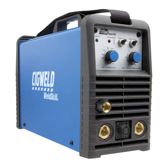
- Page 1 170 HF ® WELDSKILL INVERTER ARC WELDING MACHINE Operating Manual Version No: AA Issue Date: April 23, 2008 Manual No.: 0-5070 Operating Features:...
- Page 2 To locate your nearest distributor or service agency call +1300 654 674, or visit us on the web at www.cigweld.com.au. This Operating Manual has been designed to instruct you on the correct use and operation of your CIGWELD product. Your satisfaction with this product and its safe operation is our ultimate concern.
- Page 3 While the information contained in this Manual represents the Manufacturer's best judgement, the Manufacturer assumes no liability for its use. Weldskill 170 HF Inverter Arc Welder Instruction Manual Number 0-5070 for: Part Number W1003001 Published by: Thermadyne Industries, Inc.
-
Page 4: Table Of Contents
TABLE OF CONTENTS SECTION 1: ARC WELDING SAFETY INSTRUCTIONS AND WARNINGS ........1-1 1.01 Arc Welding Hazards ..................1-1 1.02 PRINCIPAL SAFETY STANDARDS ..............1-5 1.03 DECLARATION OF CONFORMITY ..............1-6 SECTION 2: INTRODUCTION ..................2-1 2.01 How To Use This Manual ................2-1 2.02 Equipment Identification................. - Page 5 5.03 Face Shield Maintenance ................5-1 5.04 Basic Troubleshooting ..................5-1 5.05 Welding Problems ..................5-2 5.06 Welding Power Source Problems ..............5-5 CIGWELD LIMITED WARRANTY Terms of Warranty – 2007 Warranty Schedule – 2007 GLOBAL CUSTOMER SERVICE CONTACT INFORMATION ......Inside Rear Cover...
- Page 6 THIS PAGE LEFT INTENTIONALLY BLANK...
-
Page 7: Arc Welding Safety Instructions And Warnings
WELDSKILL 170 HF INVERTER SECTION 1: ARC WELDING SAFETY INSTRUCTIONS AND WARNINGS WARNING PROTECT YOURSELF AND OTHERS FROM POSSIBLE SERIOUS INJURY OR DEATH. KEEP CHILDREN AWAY. PACEMAKER WEARERS KEEP AWAY UNTIL CONSULTING YOUR DOCTOR. DO NOT LOSE THESE INSTRUCTIONS. READ OPERATING/INSTRUCTION MANUAL BEFORE INSTALLING, OPERATING OR SERVICING THIS EQUIPMENT. - Page 8 WELDSKILL 170 HF INVERTER 2. Wear approved safety glasses. Side shields recommended. WARNING 3. Use protective screens or barriers to protect others from flash and glare; warn others not to watch the arc. ARC RAYS can burn eyes and skin; NOISE can damage hearing.
- Page 9 WELDSKILL 170 HF INVERTER 3. Remove all flammables within 35 ft (10.7 m) of the welding arc. If this is not possible, tightly cover WARNING them with approved covers. FUMES AND GASES can be hazardous to 4. Be alert that welding sparks and hot materials from your health.
- Page 10 WELDSKILL 170 HF INVERTER 4. Never allow a welding electrode to touch any cylinder. WARNING 5. Use only correct shielding gas cylinders, MOVING PARTS can cause injury. regulators, hoses, and fittings designed for the specific application; maintain them and associated Moving parts, such as fans, rotors, and belts can cut parts in good condition.
-
Page 11: Principal Safety Standards
WELDSKILL 170 HF INVERTER To reduce magnetic fields in the workplace, use the following procedures. 1. Keep cables close together by twisting or WARNING taping them. 2. Arrange cables to one side and away from the STEAM AND PRESSURIZED HOT operator. -
Page 12: Declaration Of Conformity
71 Gower St, Preston Victoria 3072 Australia Description of equipment: Welding Equipment (MMAW, GTAW) including, but not limited to CIGWELD Weldskill 170 HF and associated accessories. Serial numbers are unique with each individual piece of equipment and details description, parts used to manufacture a unit and date of manufacture. -
Page 13: Introduction
Electronic copies of this manual can also be downloaded at no charge in Acrobat PDF format by going to the Cigweld web site listed below and clicking on the Literature Library link: http://www.cigweld.com.au April 23, 2008... -
Page 14: Symbol Chart
WELDSKILL 170 HF INVERTER 2.04 Symbol Chart Note that only some of these symbols will appear on your model. Single Phase Wire Feed Function Wire Feed Towards Workpiece With Three Phase Output Voltage Off. Three Phase Static Frequency Converter- Welding Gun... -
Page 15: Description
CIGWELD. Advice in this regard can be obtained by contacting accredited CIGWELD Distributor. WARNING This equipment or any of its parts should not be... -
Page 16: Specifications
WELDSKILL 170 HF INVERTER 2.10 Specifications Description Weldskill 170 HF Inverter Power Source Part Number W1003000 Cooling Fan Cooled Welder Type Inverter Power Source with High Frequency Welding Power Source Mass 7.5kg Dimensions L 380mm x W 130 x H 255 Manufactured to Australian Standard AS60974.1-2006... -
Page 17: Installation
WELDSKILL 170 HF INVERTER SECTION 3: INSTALLATION H. Precautions must be taken against the power 3.01 Environment source toppling over. The power source must be located on a suitable horizontal surface in the These units are designed for use in environments with upright position when in use. -
Page 18: High Frequency Introduction
WELDSKILL 170 HF INVERTER 3.05 High Frequency Introduction 4. Re-radiation from Unearthed Metallic Objects: A major factor contributing to interference is re- The importance of correct installation of high radiation from unearthed metallic objects close frequency welding equipment cannot be to the welding leads. - Page 19 WELDSKILL 170 HF INVERTER 3. Computer and other control equipment. 3. Welding Cables 4. Safety critical equipment, e.g. guarding of The welding cables should be kept as short industrial equipment. as possible and should be positioned close together, running at or close to the floor level.
-
Page 20: Setup For Manual Arc Welding
WELDSKILL 170 HF INVERTER 3.06 Setup For Manual Arc Welding WARNING Before connecting the work clamp to the work and inserting the electrode in the electrode holder make sure the Mains power supply is switched off. CAUTION Remove any packaging material prior to use. Do not block the air vents at the front or rear of the Welding Power Source. -
Page 21: Setup For Tig Welding
WELDSKILL 170 HF INVERTER 3.07 Setup For TIG Welding WARNING Before connecting the work clamp to the work and inserting the electrode in the TIG torch make sure the Mains power supply is switched off. CAUTION Remove any packaging material prior to use. Do not block the air vents at the front or rear of the Welding Power Source. - Page 22 WELDSKILL 170 HF INVERTER THIS PAGE LEFT INTENTIONALLY BLANK. April 23, 2008...
-
Page 23: Operation
WELDSKILL 170 HF INVERTER SECTION 4: OPERATION 4.01 Overview Conventional operating procedures apply when using the Welding Power Source, i.e. connect work lead directly to workpiece and electrode lead is used to hold electrode. The welding current range values should be used as a guide only. -
Page 24: Front Panel Functions
WELDSKILL 170 HF INVERTER 4.03 Front Panel Functions E. Welding Current Control The welding current is increased by turning the Weld Refer to Figure 4-1 on the previous page. Current (A) control knob clockwise or decreased by A. Power ON Indicator turning the Weld Current (A) control knob anti- clockwise. -
Page 25: Arc Welding Electrodes
WELDSKILL 170 HF INVERTER 4.04 Arc Welding Electrodes 4.05 Types of Electrodes Metal arc welding electrodes consist of a core wire Arc Welding electrodes are classified into a number surrounded by a flux coating. The flux coating is of groups depending on their applications. There are applied to the core wire by an extrusion process. -
Page 26: Electrode Selection Chart
WELDSKILL 170 HF INVERTER 4.06 Electrode Selection Chart CIGWELD Electrode Selection Chart Description Diameter Pack Part No. Application 2.5mm Handipak 322135 2.5mm 2.5kg 612182 General purpose electrode suitable for all Satincraft 13 3.2mm Handipak 322136 positional welding and galvanized steel 3.2mm... -
Page 27: Size Of Electrode
If in doubt is absolutely essential to keep manganese steel cool consult your nearest Accredited CIGWELD Distributor. during welding by quenching after each weld or skip welding to distribute the heat. Suitable Electrode types are Cobalarc Austex or Cobalarc Mangcraft. -
Page 28: Welding Position
WELDSKILL 170 HF INVERTER 4.12 Welding Position The electrodes dealt with in this publication can be used in most positions, i.e. they are suitable for welding in flat, horizontal, vertical and overhead positions. Numerous applications call for welds to be made in positions intermediate between these. -
Page 29: Joint Preparations
WELDSKILL 170 HF INVERTER 4.13 Joint Preparations In many cases, it will be possible to weld steel sections without any special preparation. For heavier sections and for repair work on castings, etc., it will be necessary to cut or grind an angle between the pieces being joined to ensure proper penetration of the weld metal and to produce sound joints. -
Page 30: Arc Welding Technique
WELDSKILL 170 HF INVERTER 4.14 Arc Welding Technique Another difficulty you may meet is the tendency, after the arc is struck, to withdraw the electrode so far that A Word to Beginners the arc is broken again. A little practice will soon remedy both of these faults. -
Page 31: Making Welded Joints
WELDSKILL 170 HF INVERTER 4.19 Making Welded Joints sequence shown in Figure 4-13. The width of weave should not be more than three times the core wire Having attained some skill in the handling of an diameter of the electrode. When the joint is completely... - Page 32 WELDSKILL 170 HF INVERTER C. Vertical Welds 1. Vertical Up Tack weld a three feet length of angle iron to your work bench in an upright position. Use a 3.2mm Ferrocraft 21 electrode and set the current at 100 amps. Make yourself comfortable on a seat in front of the job and strike the arc in the corner of the fillet.
-
Page 33: Distortion
WELDSKILL 170 HF INVERTER 4.20 Distortion The metal in the weld area is stretched (plastic deformation), the job may be pulled out of shape by Distortion in some degree is present in all forms of the powerful contraction stresses (distortion), or the welding. - Page 34 WELDSKILL 170 HF INVERTER D. Presetting It is possible in some cases to tell from past experience or to find by trial and error (or less frequently, to calculate) how much distortion will take place in a given welded structure. By correct pre-...
-
Page 35: Tig Welding Filler Rods
WELDSKILL 170 HF INVERTER 4.23 TIG Welding Filler Rods Comweld Aust AWS Std Part No. Part No. Part No. Type/Application 1.6mm 2.4mm 3.2mm ER70S-4 321411 321412 For mild-medium strength LW1-6 ER70S-6 321417 321418 steels. Pipes, tubing, roll Supersteel ER70S-2 321370... - Page 36 WELDSKILL 170 HF INVERTER THIS PAGE LEFT INTENTIONALLY BLANK 4-14 April 23, 2008...
-
Page 37: Service
• The main earth wire of the electrical installation carried out by appropriately qualified persons is intact. approved by CIGWELD. Advice in this regard can be obtained by contacting an accredited CIGWELD • Power point for the Welding Power Source is Distributor. -
Page 38: Welding Problems
WELDSKILL 170 HF INVERTER 5.05 Welding Problems Description Possible Cause Remedy 1 Gas pockets or voids in weld metal A Electrodes are damp A Dry electrodes before use (Porosity) B Welding current is too high B Reduce welding current C Surface impurities such as... - Page 39 WELDSKILL 170 HF INVERTER Lack of fusion caused by dirt, electrode angle incorrect, rate of travel too high Art # A-05867_AB Lack of inter-run fusion Lack of side fusion, scale dirt, small electrode, Lack of root fusion amperage too low...
- Page 40 WELDSKILL 170 HF INVERTER Description Possible Cause Remedy 6 Non-metallic particles are trapped A Non-metallic particles may A If bad undercut is in the weld metal (slag inclusion) be trapped in undercut from present, clean slag out previous run and cover with a run from...
-
Page 41: Welding Power Source Problems
WELDSKILL 170 HF INVERTER 5.06 Welding Power Source Problems Description Possible Cause Remedy 1 The welding arc cannot be A. The Primary supply voltage A. Switch ON the Primary supply established has not been switched ON voltage B. The Welding Power Source B. - Page 42 WELDSKILL 170 HF INVERTER THIS PAGE LEFT INTENTIONALLY BLANK April 23, 2008...
-
Page 43: Cigweld Limited Warranty
“Purchaser” that its products will be free of defects in workmanship or material. Should any failure to conform to this warranty appear within the time period applicable to the CIGWELD products as stated below, CIGWELD shall, upon notification thereof and substantiation that the product has been stored, installed, operated, and maintained in accordance with CIGWELD’s specifications, instructions,... -
Page 44: Terms Of
CIGWELD. 4. CIGWELD declares that, to the extent permitted by law, it hereby limits its liability in respect of the supply of goods which are not of a kind ordinarily acquired for personal, domestic or household use or consump- tion to any one or more of the following (the choice of which shall be at the option of CIGWELD). - Page 45 Accredited Distributor of the equipment. Notwithstanding the foregoing, in no event shall the war- ranty period extend more than the time stated plus one year from the date CIGWELD delivered the product to the Accredited Distributor. Unless otherwise stated the warranty period includes parts and labour. CIGWELD reserves the right to request documented evidence of date of purchase.
-
Page 47: Global Customer Service Contact Information
48000 Rawang Selangor Darul Ehsan 800-426-1888 West Malaysia Fax: 800-535-0557 Telephone: 603+ 6092 2988 Email: sales@thermalarc.com Fax : 603+ 6092 1085 Thermadyne Canada Cigweld, Australia 2070 Wyecroft Road 71 Gower Street Oakville, Ontario Preston, Victoria Canada, L6L5V6 Australia, 3072 Telephone: (905)-827-1111... - Page 48 Corporate Headquarters 71 Gower Street Preston, Victoria, Australia, 3072 Telephone: +61 3 9474 7400 FAX: +61 3 9474 7488 Email: cigweldsales@cigweld.com.au www.cigweld.com.au...
Need help?
Do you have a question about the 170 HF and is the answer not in the manual?
Questions and answers