Table of Contents
Advertisement
Quick Links
590 Series
DC Digital
Converter
Product Manual
HA467078 Issue 5
Compatible with Version 4.x Software
Copyright 2005 SSD Drives Limited (formerly Eurotherm Drives Limited)
All rights strictly reserved. No part of this document may be stored in a retrieval system, or transmitted in any form or by
any means to persons not employed by an SSD Drives company without written permission from SSD Drives Ltd.
Although every effort has been taken to ensure the accuracy of this document it may be necessary, without notice, to
make amendments or correct omissions. SSD Drives cannot accept responsibility for damage, injury, or expenses
resulting therefrom.
Advertisement
Table of Contents

Summary of Contents for SSD Drives 590 Series
- Page 1 All rights strictly reserved. No part of this document may be stored in a retrieval system, or transmitted in any form or by any means to persons not employed by an SSD Drives company without written permission from SSD Drives Ltd.
- Page 2 SSD Drives warrants the goods against defects in design, materials and workmanship for the period of 12 months from the date of delivery on the terms detailed in SSD Drives Standard Conditions of Sale IA058393C. SSD Drives reserves the right to change the content and product specification without notice. Cont.2...
- Page 3 Safety Information Requirements IMPORTANT: Please read this information BEFORE installing the equipment. Intended Users This manual is to be made available to all persons who are required to install, configure or service equipment described herein, or any other associated operation. The information given is intended to highlight safety issues, and to enable the user to obtain maximum benefit from the equipment.
- Page 4 The specifications, processes and circuitry described herein are for guidance only and may need to be adapted to the user’s specific application. Refer to page 5-1. SSD Drives does not guarantee the suitability of the equipment described in this Manual for individual applications.
-
Page 5: Table Of Contents
Contents Contents Page Chapter 1 G E T T I N G T A R T E D Introduction ....................1-1 Equipment Inspection and Storage .............. 1-2 Packaging and Lifting Details ..............1-2 About this Manual ..................1-2 Initial Steps ......................1-2 How the Manual is Organised .................1-3 Chapter 2 A V E R V I E W O F T H E... - Page 6 Contents Contents Page Chapter 4 O P E R A T I N G T H E O N V E R T E R Pre-Operation Checks .................. 4-1 Setting-up the Converter ................4-2 Calibration ......................4-2 Switchable Calibration Panel ...............4-2 Analog Tacho Calibration Option Board ............4-3 Microtach/Encoder Feedback Option Board ..........4-3 Selecting Speed Feedback ..................4-4...
- Page 7 Contents Contents Page Menu Viewing Levels ....................5-5 Selecting the Display Language................5-5 Password Protection ....................5-6 To Activate Password Protection ..............5-6 To Deactivate Password Protection ...............5-6 To Reactivate Password Protection..............5-6 How to Save, Restore and Copy your Settings..........5-7 Saving Your Application ..................5-7 Restoring Saved Settings ..................5-7 Copying an Application ...................5-7 Chapter 6 P...
- Page 8 Contents Contents Page PID ......................6-39 RAISE/LOWER...................6-42 RAMPS .....................6-44 SETPOINT SUM 1 ..................6-48 SETPOINT SUM 2 ..................6-49 SPEED LOOP ....................6-51 ADVANCED....................6-55 STANDSTILL .....................6-56 STOP RATES .....................6-57 SYSTEM PORT P3..................6-59 TAPER CALC.....................6-60 TENS+COMP CALC.................6-61 TORQUE CALC..................6-63 USER FILTER .....................6-64 Chapter 7 T R I P S A N D A U L T...
- Page 9 A I N T E N A N C E A N D E P A I R Routine Maintenance..................8-1 Repair ......................8-1 Saving Your Application Data ..................8-1 Returning the Unit to SSD Drives ................8-1 Technical Support Checks..................8-2 Chapter 9 C O N T R O L O O P S Principle of Operation ..................
- Page 10 Contents Contents Page Terminal Information (Option Boards) ..............11-14 Termination Tightening Torque ................11-15 Mechanical Details ....................11-15 Cooling ......................11-16 Chapter 12 C E R T I F I C A T I O N F O R T H E O N V E R T E R Requirements for EMC Compliance ............
- Page 11 Contents Contents Page Chapter 13 S T A N D A R D A N D P T I O N A L Q U I P M E N T Standard Equipment................... 13-1 Power Board Circuit Descriptions ................13-1 590/591 (AH385851U002, U003, U004, U005) ........13-1 590/591 (AH385621U001) ..............13-5 598/599 Power Board (AH385128U009) ..........13-10 Heatsink Cooling Fan Connections ..............13-10...
- Page 12 Contents Contents Page Cont.12...
-
Page 13: S T A R T E D Introduction
Introduction System Design The 590 Series Converter is designed for use in a suitable enclosure, with associated control equipment. The unit accepts standard three-phase ac supply voltages in the range 110V to 660V, depending upon the model, and is suitable for the powering of DC shunt field and permanent magnet motors, providing controlled dc output voltage and current for armature and field. -
Page 14: Equipment Inspection And Storage
Use the manual to help you plan the following: Installation Know your requirements: • certification requirements, CE/UL/c-UL conformance • conformance with local installation requirements • supply and cabling requirements Programming (MMI or suitable PC programming tool only) 590 Series Digital Converter... -
Page 15: How The Manual Is Organised
Application Block Diagram You will find this at the rear of the manual. The pages unfold to show a complete block diagram, this will become your programming tool as you become more familiar with the software. 590 Series Digital Converter... - Page 16 Getting Started 590 Series Digital Converter...
-
Page 17: Converter
5721 Operator Station and Analog/Digital Inputs and Outputs Analog/Digital Inputs and Outputs By plugging in a COMMS Option Board, the Converter can be linked into a network and controlled by a PLC/SCADA or other intelligent device. 590 Series DC Digital Converter... -
Page 18: Component Identification
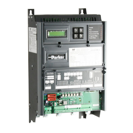
Auxiliary Serial Port (P2) Field wiring terminals Man-Machine Interface (MMI) keypad Control terminals Status LEDs Control board MMI display Tacho/Encoder/Microtach option board IP20 Top Cover Main Serial Port COMMS option module (P1) IP20 Fan Housing (where fitted) 590 Series DC Digital Converter... -
Page 19: Control Features
• Standstill logic • Stall protection • Fully computerised with first fault latch and Diagnostics automatic display • Digital LCD monitoring • Full diagnostic information available on RS422/RS485 • LED circuit state indication Table 0-1 Control Features 590 Series DC Digital Converter... - Page 20 An Overview of the Converter 590 Series DC Digital Converter...
-
Page 21: Understanding The Product Code
3 = Wire-ended Encoder 4 = 5901 Glass Fibre Microtach One character specifying the communications protocol and its hardware implementation method: 0 = No serial link 1 = Fitted RS485 serial link 2 = PROFIBUS 590 Series DC Digital Converter... - Page 22 Two characters specifying special options (hardware): 00 = No special options 01 to 99 = Documented special options Three characters specifying special options (software): 000 = No special options 001 to 999 = Documented special options 590 Series DC Digital Converter...
-
Page 23: Nstalling The
Installing the Converter NSTALLING THE ONVERTER IMPORTANT: Read Chapter 12: “Certification for the Converter” before installing this unit. Refer to Installation Drawings, page 3-20 for further information. Mechanical Installation 35A - 70A 110A - 150A 180A - 270A 360A 450A * 720A - 800A * * Cooling fan assemblies not shown Current Rating (A) -
Page 24: Mounting The Converter
Installing the Converter Mounting the Converter General installation details are given below for mounting the Converter, however, if you are installing the unit with an EMC filter refer to “External AC Supply EMC Filter Installation”, page 3-17. Mount the unit vertically on a solid, flat, vertical surface. It is mounted using bolts or screws into four fixing points (keyhole slots). -
Page 25: Electrical Installation
Installing the Converter Electrical Installation IMPORTANT: Please read the Safety Information on page Cont. 3 & 4 before proceeding. WARNING! Ensure that all wiring is electrically isolated and cannot be made “live” unintentionally by other personnel. Note: Refer to Chapter 11: “Technical Specifications” for additional Cabling Requirements and Terminal Block Wire Sizes. -
Page 26: Minimum Connection Requirements
Installing the Converter Minimum Connection Requirements Note: Because of the complexity of showing all possible configurations, this Chapter deals only with a `general purpose’ operation as a basic speed controller. Special wiring options usually form part of a customer-specific system and connection details will be provided separately. - Page 27 Installing the Converter Figure 3-4 Minimum Connection Requirements (`general purpose’ configuration) 590D DC Digital Converter - HA467078...
-
Page 28: Protective Earth Connections (Pe)
Installing the Converter Protective Earth Connections (PE) MINIMUM CONNECTION 3 PHASE REQUIREMENT SUPPLY PROTECTIVE EARTH HIGH SPEED FUSES FILTER OPTIONAL START CONTACTOR AC LINE CHOKE STAR POINT EARTH NEAR DRIVE USE INTERNAL FIELD CONNECTION FOR EMC COMPLIANCE G4/G2G3/G1 FIELD ARMATURE IMPORTANT: The VSD and filter (if fitted) must be permanently earthed. -
Page 29: Power Wiring Connections
The choice of ac or dc contactors is a user preference. SSD Drives prefers ac contactors as they isolate the converter and motor when not in use. The only restriction on the use of a dc contactor is that an interlocking contact should be provided into the Enable input. - Page 30 CONNECTION REQUIREMENT armature circuit. A DC fuse or a high speed circuit breaker will provide this protection, if in doubt consult the SSD Drives Engineering Department. ARMATURE 590D DC Digital Converter - HA467078...
- Page 31 Installing the Converter External AC Field (D1, D2) If an external field supply is required to AC FIELD the controller for application reasons, SUPPLY connect this supply to terminals D1 and D2. The magnitude of this voltage is determined by the desired field voltage. The supply must be protected externally with suitable fuses.
-
Page 32: Control Wiring Connections
Close the terminal cover. IMPORTANT: All connections made to terminal blocks A, B and C must be isolated signal voltages. If in doubt about the connection of the DC motor to the controller check with SSD Drives Engineering Department. - Page 33 3-11 Installing the Converter Thermistor (C1, C2) MINIMUM CONNECTION The motor temperature alarm (THERMISTOR) cannot be inhibited REQUIREMENT in software. Terminals C1 and C2 must be linked if sensors are not fitted. We recommend that you protect the dc motor against overtemperature by the use of temperature sensitive resistors or switches in the field and interpole windings of the machine.
- Page 34 3-12 Installing the Converter by PROG STOP I LIM, PROG STOP LIMIT and PROG STOP TIME. If the signal is re- applied to Terminal B8, the motor remains stationary until a new Start command is applied to Terminal C3 (Start/Run). Emergency Stop Additional terminals, Terminal B8 (Program Stop) and Terminal B9 (Coast Stop), provide extra facilities for the control of the regenerative controller:...
- Page 35 Maximum Microtach frequency 50kHz, i.e. with a 1000 lines per revolution Microtach, the motor speed cannot exceed 3000 rpm. For specification and connection information refer to SSD Drives or the appropriate Technical Manual. Wire-Ended Encoder (G1, G2, G3, G4, G5, G6) Refer to Chapter 13: “Standard and Optional Equipment”...
-
Page 36: Motor Field Connections
3-14 Installing the Converter Motor Field Connections The FIELD CONTROL function block controls the motor field. The FLD CTRL MODE IS parameter allows you to select either Voltage or Current Control mode. • In Voltage Control mode, the RATIO OUT/IN parameter is used to scale the motor field output voltage as a percentage of the input supply voltage. -
Page 37: Power Board - Pcb Reference 385621
3-15 Installing the Converter Power Board - PCB Reference 385621 This power board (printed with the above number) can be adjusted for use with an internal or external motor field supply: Internal Motor Field (default for this board) Terminals D3 and D4, the motor field outputs, are energised when the 3-phase supply to L1/L2/L3 is energised and the internal motor field is used. -
Page 38: Power Board - Pcb Reference 385128
3-16 Installing the Converter Power Board - PCB Reference 385128 External Motor Field (default for this board) This power board (printed with the above number) is supplied in external stack options using an external motor field supply. Connect the external supply to busbars FL1 and FL2. -
Page 39: Power Board - Pcb Reference 385621
3-17 Installing the Converter Power Board - PCB Reference 385621 EXA+ EXA- terminals D5 & D6 contactor fuses External AC Supply EMC Filter Installation Refer to Chapter 11: “Technical Specifications” - Environmental Details, and External AC Supply (RFI) Filters and Line Choke for selection details. A filter is used with the Converter to reduce the line conducted emissions produced by the Converter. -
Page 40: Operating Conditions
As with all power electronic drives, conducted emissions increase with motor cable length. EMC conformance is only guaranteed up to a cable length of 50m. The cable length can be increased. Refer to SSD Drives for more information. 590D DC Digital Converter - HA467078... -
Page 41: Earth Fault Monitoring Systems
This has been minimised in SSD Drives filters, but may still trip out any circuit breaker in the earth system. In addition, high frequency and dc components of earth leakage currents will flow under normal operating conditions. -
Page 42: Installation Drawings
3-20 Installing the Converter Installation Drawings Converter Installation Drawings Figure 3-5 35A & 70A Stack Assembly 590D DC Digital Converter - HA467078... - Page 43 3-21 Installing the Converter Figure 3-6 110A & 150A Stack Assembly 590D DC Digital Converter - HA467078...
- Page 44 3-22 Installing the Converter Figure 3-7 180A Stack Assembly 590D DC Digital Converter - HA467078...
- Page 45 3-23 Installing the Converter Figure 3-8 270A Stack Assembly 590D DC Digital Converter - HA467078...
- Page 46 3-24 Installing the Converter Figure 3-9 360A Stack Assembly 590D DC Digital Converter - HA467078...
- Page 47 3-25 Installing the Converter Figure 3-10 450A Stack Assembly 590D DC Digital Converter - HA467078...
- Page 48 3-26 Installing the Converter Figure 3-11 720A Stack Outline Drawing 590D DC Digital Converter - HA467078...
- Page 49 3-27 Installing the Converter Figure 3-12 720A Stack Outline Drawing 590D DC Digital Converter - HA467078...
- Page 50 3-28 Installing the Converter Figure 3-13 720A Stack Assembly - Standard Mounting 590D DC Digital Converter - HA467078...
- Page 51 3-29 Installing the Converter Figure 3-14 720A Stack Assembly - Installation Drawing 590D DC Digital Converter - HA467078...
-
Page 52: External Stack Installation Drawings
3-30 Installing the Converter External Stack Installation Drawings Figure 3-15 External Stack Assembly 590D DC Digital Converter - HA467078... - Page 53 3-31 Installing the Converter Figure 3-16 Wiring Diagram for 4 Quad External Stack 590D DC Digital Converter - HA467078...
- Page 54 3-32 Installing the Converter Figure 3-17 Wiring Diagram for 2 Quad External Stack 590D DC Digital Converter - HA467078...
-
Page 55: Filter Installation Drawings
3-33 Installing the Converter Filter Installation Drawings M8 STUD SET 3x PLAIN WASHER 2x NUTS TYP IN 8 POSNS FIXING CENTRES LINE E L1 DRIVE UNIT 590 35 AMP FIXING FIXING CENTRES CENTRES E L1 LOAD 4 HOLES M6 CLEARANCE LINE CHOKE FITTED BETWEEN FILTER MAYBE MOUNTED... - Page 56 3-34 Installing the Converter 3x PLAIN 2x NUTS WASHER NYLON BUSH M8 EARTH STUDS M10 STUDS FOR L1,2 & 3. FIXING 300 FIX CENTRES 14.5 4 HOLES M8 LINE CLEARANCE DOUBLE KEYHOLE TYP IN 4 POSNS FIXING FIXING DRIVE UNITS CENTRES CENTRES 590 150 &...
- Page 57 3-35 Installing the Converter 445 mm 380 mm 680 mm Filters mounted flat DRIVE UNITS against the wall using 785 mm 590 360 AMP 4 x M8 fixings as shown. LINE CHOKE FITTED BETWEEN FILTER & DRIVE 360 AMP Figure 3-22 Filter Mounting Details using 2 x Part No. CO389456 for 590 360 Amp 590D DC Digital Converter - HA467078...
-
Page 58: Ac Line Choke Installation Drawing
3-36 Installing the Converter AC Line Choke Installation Drawing IMPORTANT: Always use the specified ac line choke with the Converter. Choke Rating Dimensions (mm) Terminal Hole Type (DC) ∅ ∅ CO055192 27.5 ∅7 50µH CO055193 27.5 7.5 72.5 92.5 155 302.5 ∅7 50µH CO055253... -
Page 59: Pre-Operation Checks
• If there is any doubt about the integrity of a particular installation, insert a high wattage resistor, i.e. fire elements, in series with the motor armature. • Check external run contacts are open. • Check external speed setpoints are all zero. 590 Series DC Digital Converter... -
Page 60: Setting-Up The Converter
Note: If using an external stack controller, set the switches for one quarter less current than you require, i.e. if you want 12A of field current, set the switches to 9A. (This allows for a different turns ratio used in the current transformers of external stack modules). 590 Series DC Digital Converter... -
Page 61: Analog Tacho Calibration Option Board
A “1” indicates that the switch is ON. The illustration on the previous page shows a VA CAL setting of 200V. Note: Calibration up to 700V is possible with external stacks. Refer to SSD Drives. Analog Tacho Calibration Option Board... -
Page 62: Selecting Speed Feedback
↑ (UP) key to reveal other selections). 2 SPEED LOOP The selections are ARM VOLTS FBK, ANALOG TACH, ENCODER SPEED FBK SELECT and ENCODER/ANALOG. Note: Refer to Chapter 13: “Standard and Optional Equipment” - Speed Feedback Option Boards for further information. 590 Series DC Digital Converter... -
Page 63: Initial Start-Up Routine
Note: Save any parameters that have been changed. Refer to Chapter 5: “The Man-Machine Interface (MMI)” - How to Save, Restore and Copy your Settings. MMI Menu Map 1 SETUP PARAMETERS 2 SPEED LOOP SPEED FBK SELECT 590 Series DC Digital Converter... - Page 64 Terminals D4 and D3. This is high voltage DC, proceed with caution. Do not continue if this is incorrect, switch off all supplies and check connections. Refer to 9.1 or 9.2 on the next page: 590 Series DC Digital Converter...
- Page 65 Enable input C5 will affect the state of the RUN LED. 11 If the STANDSTILL LOGIC parameter in the STANDSTILL menu at level 2 is ENABLED, temporarily set it to DISABLED. MMI Menu Map 1 SETUP PARAMETERS 2 STANDSTILL STANDSTILL LOGIC 590 Series DC Digital Converter...
- Page 66 If no current is 1 DIAGNOSTICS flowing, switch off and check the armature connections. CURRENT FEEDBACK Is the motor connected to the converter? Verify that calibration has been carried out correctly. 590 Series DC Digital Converter...
- Page 67 • The MICROTACH/Encoder should give an absolute rotational speed for which adjustment is unnecessary however the motor speed may not be the relevant factor thus speed of rotation can be altered by simply adjusting the calibration. 590 Series DC Digital Converter...
- Page 68 • If the motor is overloaded and the current provided by the controller is not enough to maintain rotation, i.e. it stalls, the controller will trip out showing STALL TRIP alarm, if enabled. 590 Series DC Digital Converter...
-
Page 69: Performance Adjustment
If the Converter is using Microtach/Encoder feedback, then the speed response can be monitored on Terminal A7. Adjust the two parameters until you have rapid change of speed feedback between the setpoint values, but with minimum overshoot. 590 Series DC Digital Converter... -
Page 70: Starting And Stopping Methods
Motor coasts to rest Overrides Program Stop and Normal Stop Program Stop Motor decelerates at STOP TIME Overrides Normal Program Stop rate Stop Start/Run Motor decelerates at PROG STOP TIME -- (Normal Stop) Normal Stop rate 590 Series DC Digital Converter... -
Page 71: Normal Stop (C3)
(DEFAULT 2%) DRIVE REMAINS ENABLED FOR CONTACTOR DELAY IF STOP ZERO SPEED < 0.25% Enable DRIVE ENABLE =ENABLED (DISPLAY DIAGNOSTIC) DRIVE ENABLE = DISABLED DRIVE RUN LED Indicators AND START CONTACTOR CONTACTOR DELAY (DEFAULT 1.0 SECS) 590 Series DC Digital Converter... - Page 72 SPEED FEEDBACK Actual Speed STOP ZERO SPEED (DEFAULT 2% ) STOP LIMIT ( DEFAULT 60.0 SEC ) Indicators DRIVE RUN LED AND START CONTACTOR DRIVE ENABLE =ENABLED DRIVE RUN LED & START CONTACTOR DRIVE ENABLE =DISABLED 590 Series DC Digital Converter...
-
Page 73: Program Stop (B8)
OVERLOAD CAPABILITY OF MOTOR/DRIVE SPEED (DEFAULT 2%) DRIVE IS DISABLED AND CONTACTOR TURNS OFF BELOW Indicators STOP ZERO SPEED DRIVE RUN LED AND START CONTACTOR DRIVE ENABLE =ENABLED DRIVE RUN LED AND START CONTACTOR DRIVE ENABLE =DISABLED 590 Series DC Digital Converter... -
Page 74: Coast Stop (B9)
When a trip condition is detected, a similar stopping method to Coast Stop is used. The power stack cannot be re-enabled until the trip condition has been cleared and successfully reset. Refer to Chapter 7: “Trips and Fault Finding” for further details. 590 Series DC Digital Converter... -
Page 75: Normal Starting Method
2. Apply 24V to Terminal C4 (Jog Mode) Note: The Converter will not start if there are alarms present. Start the Converter using a crawl speed, in Forward or Reverse. Refer to Chapter 6: “Programming Your Application” - JOG/SLACK for further information. 590 Series DC Digital Converter... - Page 76 4-18 Operating the Converter 590 Series DC Digital Converter...
-
Page 77: Introducing The Mmi
Parameter - Returns to the parameter list. Trip Acknowledge - Acknowledges displayed Trip or Error message. Navigation - Displays the next Menu level, or the first parameter of the MENU current Menu. Parameter - Allows a writable parameter to be modified 590 Series DC Digital Converter... -
Page 78: Led Indications
In normal run condition, all LEDs on the MMI are illuminated. Any LED which is off indicates a condition which prevents operation of the controller. HINT: The general rule for LED indications is “ON IS GOOD, OFF IS BAD” 590 Series DC Digital Converter... -
Page 79: The Menu System
Refer to “The Menu System Map” to see how the menu is mapped. HINT: Remember that because the Menu and Parameter lists are looped, the ↑ key can quickly move you to the last Menu or Parameter in the loop. 590 Series DC Digital Converter... -
Page 80: The Menu System Map
DIGITAL INPUTS DIGIN 3 (C8) DIGITAL INPUT C4 DIGITAL INPUT C5 DIGITAL OUTPUTS DIGOUT 1 (A5) DIGOUT 3 (B7) CONFIGURE 5703 BLOCK DIAGRAM FULL & REDUCED VIEWS LINK 1 INTERNAL LINKS FULL VIEW ONLY LINK 11 590 Series DC Digital Converter... -
Page 81: Changing A Parameter Value
The choice of display language is selected by the LANGUAGE parameter in MENUS menu. Remember to perform a PARAMETER SAVE if you need the new language to be saved on power-down. The available languages are: ENGLISH and FRENCH. However, other languages are available by contacting SSD Drives. 590 Series DC Digital Converter... -
Page 82: Password Protection
This clears the value of the password in the CHANGE PASSWORD menu and instead displays “****”. Note: At default the password is 0000, password protection is not activated because 0000 is the value for both CHANGE PASSWORD and ENTER PASSWORD. 590 Series DC Digital Converter... -
Page 83: How To Save, Restore And Copy Your Settings
Copying an application requires a host computer connection to the Converter’s P3 port. Information can then be downloaded to the computer (and uploaded to the Converter). Refer to Chapter 14: “Serial Communications” for further information. 590 Series DC Digital Converter... - Page 84 The Man-Machine Interface (MMI) 590 Series DC Digital Converter...
-
Page 85: Programming With Block Diagrams
You can program the Converter for specific applications using the MMI or suitable programming tool, such as “ConfigEd Lite” which is SSD Drives’ block programming software. The Converter is supplied with a basic set-up which can be used as a starting point for application-specific programming. -
Page 86: Saving Your Modifications
A function block may also be represented by more than one MMI menu, e.g. FIELD MAX VALUE CONTROL. In contrast, the DIAGNOSTICS menu on the MMI is greatly reduced in the MIN VALUE DIAGNOSTICS function block, the remaining parameters being included in related function DESTINATION TAG blocks. 590 Series DC Digital Converter... -
Page 87: Hexadecimal Representation Of Trips
“2” in digit 2, (8+2 = 10, displayed as A) and an 8 in digit 1. This in turn represents the active trips FIELD FAILED, ENCODER FAILED, OVERVOLTS (VA) and HEATSINK TRIP (an unlikely situation). 590 Series DC Digital Converter... -
Page 88: Function Block Descriptions
BISYNCH SUPPORT 5703 SUPPORT LINK 11 & LINK 12 6-34 TAPER CALC 6-60 TENS+COMP CALC 6-61 TORQUE CALC 6-63 USER FILTER 6-64 * These function blocks contain parameters from the DIAGNOSTICS menu on the MMI. 590 Series DC Digital Converter... -
Page 89: Analog Inputs
The minimum value of the scaled analog input ANIN 1 (A2) to ANIN 5 (A6) Refer to the DIAGNOSTICS function block description, page 6-18. OUTPUT Range: 0 to 499 (DESTINATION TAG) The destination Tag No. of the scaled analog input value. 590 Series DC Digital Converter... - Page 90 Programming Your Application Functional Description Configurable Analog Inputs CALIBRATION MAX VALUE OUTPUT MIN VALUE DIAGNOSTIC 590 Series DC Digital Converter...
-
Page 91: Analog Outputs
Offset value added to the normal output value after the scaler and before the modulus. MODULUS Range: TRUE/FALSE Unsigned analog output enable ANOUT 1 (A7) to ANOUT 2 (A8) Refer to the DIAGNOSTICS function block description, page 6-18. Functional Description Configurable Analog Outputs OFFSET MODULUS INPUT DIAGNOSTIC 10V CAL 590 Series DC Digital Converter... -
Page 92: Aux I/O
Software analog output 1. ANOUT 2 Range: -100.00 to 100.00 % Software analog output 2. JOG/SLACK Reserved parameter for use by SSD Drives. ENABLE Reserved parameter for use by SSD Drives. START (C3) Refer to the DIAGNOSTICS function block description, page 6-18. - Page 93 ANALOG AUX POINTS ARE AVAILABLE. THESE AUX I/O POINTS ALLOW INPUTS OR SERIAL INFORMATION TO DRIVE ENABLE TO BE CONNECTED TO OUTPUTS. (INPUTS MAY BE SENT TO THESE TAG DESTINATIONS AND OUTPUTS MAY READ THESE LOCATIONS AS SOURCE TAGS). 590 Series DC Digital Converter...
-
Page 94: Aux Port P2
SRL LINK ENABLE Range: ENABLED/DISABLED Enables port operation. GROUP ID (GID) Range: 0 to 7 The SSD Drives protocol group identity address. UNIT ID (UID) Range: 0 to 15 The SSD Drives protocol unit identity address. PROTOCOL Range: See below Selects the protocol to be used. -
Page 95: Calibration
Range: 0.0 to 100.0 % The speed feedback alarm compares speed feedback to armature voltage. The alarm level is the threshold which the difference between the two signals should exceed for the alarm to activate. 590 Series DC Digital Converter... - Page 96 Trim adjustment of the motor field current to give exactly 100% at the required actual current value (e.g. 1.5A etc.). Note: Primary field calibration is achieved by adjusting IF calibration using SW1 - 3. POSITION COUNT Reserved parameter for use by SSD Drives. POSITION DIVIDER Reserved parameter for use by SSD Drives. TERMINAL VOLTS Refer to the DIAGNOSTICS function block description, page 6-18.
- Page 97 TO INHIBIT ALARMS D:15 AT ZERO SPEED FROM STANDSTILL BIPOLAR ARMATURE I (A9 ) ARMATURE CURRENT -10V -0 +10V A9 OR 0- +10V lial FIELD I. CAL 1.0000 FIELD D:23 ACCT TO FIELD FIELD I FBK CONTROL 590 Series DC Digital Converter...
-
Page 98: Current Loop
Negative current clamp in Bipolar Clamp mode. Note on bipolar current clamps: these clamps in bipolar mode can cross-over onto the same quadrant as long as the POS. I CLAMP is always greater (algebraically) than the NEG. I CLAMP. 590 Series DC Digital Converter... - Page 99 AUTOTUNE Range: ON/OFF This is the autotune function trigger input. ILOOP SUSPEND Reserved parameter for use by SSD Drives. AT CURRENT LIMIT Refer to the DIAGNOSTICS function block description, page 6-18. CURRENT FEEDBACK Refer to the DIAGNOSTICS function block description, page 6-18.
- Page 100 IDMD isolate removes speed loop demand and selects analog I/P 2 as current regulator demand. IDMD isolate is overridden by program stop and stop to return drive to speed regulation. Note 2: Regen mode disable prevents negative current demand. Non-regenerative drives should have regen mode disabled. 590 Series DC Digital Converter...
-
Page 101: Current Profile
This sets the current limit value at or above speed break-point 2, provided the other current limits are greater than this setting. Functional Description Current Limit IMAX BRK 1 (SPD1) IMAX BRK 2 (SPD2) Speed Demand SPD BRK 1 (LOW) SPD BRK 2 (HIGH) 590 Series DC Digital Converter... -
Page 102: Diagnostics
Scaled field current feedback. (Refer to CALIBRATION, page 6-11) TACH INPUT (B2) Range: -300.00% to 300.00% Scaled analog tachogenerator feedback. (Refer to CALIBRATION, page 6-11) ENCODER Range: 0 RPM to 6000 RPM Encoder speed feedback in RPM. (Refer to CALIBRATION, page 6-11) 590 Series DC Digital Converter... - Page 103 (Refer to CALIBRATION, page 6-11) RAMPING Tag No. 113 - D:16 TRUE/FALSE If the difference between the ramp input and the ramp output is greater than the RAMP THRESHOLD, then RAMPING is TRUE. (Refer to RAMPS, page 6-44) 590 Series DC Digital Converter...
- Page 104 Tag No. 68 - D:32 ON/OFF Start/Run terminal. (Refer to AUX I/O, page 6-8) DIGITAL INPUT (C4) Tag No. 69 - D:33 ON/OFF Jog/Take-up Slack terminal. (Refer to DIGITAL INPUTS, page 6-24 and AUX I/O, page 6-8) 590 Series DC Digital Converter...
- Page 105 Tag No. 308 - D:50 -300.00% to 300.00% Scaled analog tachogenerator feedback. (Refer to CALIBRATION, page 6-11) ENCODER Tag No. 206 - D:51 0 RPM to 6000 RPM Encoder speed feedback in RPM. (Refer to CALIBRATION, page 6-11) 590 Series DC Digital Converter...
-
Page 106: Diameter Calc
This is the output of the block and it can be connected to the appropriate points in the winder block. MOD OF LINE SPEED Reserved parameter for use by SSD Drives. MOD OF REEL SPEED Reserved parameter for use by SSD Drives. - Page 107 Circumference = πD or Line Speed (S) = Reel Speed (ωr) x D Thus D = ωr i.e. D ∝ Line Speed (S) Reel Speed (ωr ) Therefore with the web intact we can calculate the diameter from the two speeds 590 Series DC Digital Converter...
-
Page 108: Digital Inputs
VALUE TRUE and VALUE FALSE. Inverting the digital input is Value True Output therefore simple; set VALUE TRUE to 0.00% and VALUE FALSE to Value False 0.01% or any other non-zero number. 590 Series DC Digital Converter... - Page 109 If terminal C5 is used for anything other than “drive enable”, i.e. DESTINATION TAG (Tag No. 495) is not set to 497, then the ENABLE parameter, Tag No. 497, must be set to ON, otherwise the drive will not run. 590 Series DC Digital Converter...
-
Page 110: Digital Outputs
Output set TRUE for absolute or modulus of the Tag No. value. DIGOUT 1 (B5) to DIGOUT 3 (B7) Refer to the DIAGNOSTICS function block description, page 6-18. Functional Description Configurable Digital Outputs INVERTED MODULUS INPUT THRESHOLD DIAGNOSTIC 590 Series DC Digital Converter... -
Page 111: Field Control
This is the proportional gain adjustment of the field current PI loop. The default of 0.10 is equivalent to a real gain of 10. INT. GAIN Range: 0.00 to 100.00 This is the integral gain adjustment of the field current PI loop. 590 Series DC Digital Converter... - Page 112 Reserved" Menu which is primarily for factory use only and requires the “super” password.) FIELD ENABLE Refer to the DIAGNOSTICS function block description, page 6-18. FIELD DEMAND Refer to the DIAGNOSTICS function block description, page 6-18. FLD. FIRING ANGLE Refer to the DIAGNOSTICS function block description, page 6-18. 590 Series DC Digital Converter...
- Page 113 EMF LAG 40.00 0.30 EMF GAIN BEMF FBK LEAD TO FIELD BEMF FBK LAG CURRENT LOOP FLD CLAMP CURRENT VARS BACK EMF MOTOR FEEDBACK BEMF FILTER CALIBRATION 178 MAX VOLTS 100.00% 100.00% 179 MIN FLD CURRENT 590 Series DC Digital Converter...
-
Page 114: Inhibit Alarms
Inhibits the speed feedback alarm. ENCODER ALARM Range: ENABLED/INHIBITED Inhibits the encoder option board alarm. READY Reserved parameter for use by SSD Drives. HEALTHY Reserved parameter for use by SSD Drives. HEALTH WORD Range: 0000 to FFFF The hexadecimal sum of any alarms present. Refer to Chapter 7: “Trips and Fault Finding” - Alarm Messages. - Page 115 SPDFBK ALM LEVEL ENCODER ALARM ENCODER ALARM ENABLED ENCODER FEEDBACK SELECTED AND ERROR DETECTED HEALTH RESET TRUE TRIP RESET DRIVE START NOTE [1]: FIELD FAIL THRESHOLD IS 6% IN CURRENT CONTROL 12% IN VOLTAGE CONTROL 590 Series DC Digital Converter...
-
Page 116: Jog/Slack
Ramp Time Contactor Tag No Stop False Setpoint Default Stop True Setpoint Default False Setpoint Default Take-Up Slack 1 False Setpoint + Take-Up Slack 1 Default Take-Up Slack 2 True Setpoint + Take-Up Slack 2 Default 590 Series DC Digital Converter... -
Page 117: Block Diagram
Block Diagram TAKE UP 1 TAKE UP 2 MIN SPEED RAMP INPUT (see RAMPS % S-RAMP function block) (from RAMPS function block) (see RAMPS function block) JOG 1 CRAWL SPEED JOG 2 RAMP RATE Jog/Slack Function 590 Series DC Digital Converter... -
Page 118: Link 11 & Link 12
OUTPUT between two inputs (INPUT and AUX INPUT). The functionality of the various MODE selections are shown in the table. COMPARATOR MODULUS SIGN CHANGER INVERTER SWITCH OUTPUT Range: 0 to 499 (DESTINATION TAG) 590 Series DC Digital Converter... - Page 119 If ADVANCED = ON DESTINATION = Modulus of SOURCE COMPARATOR If ADVANCED = OFF DESTINATION = SOURCE If ADVANCED = ON If SOURCE < AUX SOURCE DESTINATION = 0 If SOURCE > AUX SOURCE DESTINATION = 1 590 Series DC Digital Converter...
-
Page 120: Main Port P1
4800 9600 (default) 19200 ESP SUP. (ASCII) Range: ENABLED/DISABLED Enable if communicating with a unit using SSD Drives' own ESP protocol. CHANGEBAND (BIN) Range: 0.00% to 327.67% Percentage change in value to trigger a BINARY Enquiry Poll update. ERROR REPORT Range: 0000 to FFFF Displays the last error as a hexadecimal code. -
Page 121: Menus
This setting affects the speed at which the menu is stepped through when an MMI key (↑,↓,M,E) is pressed or held down. Increasing the value slows the menu. LANGUAGE Range: ENGLISH/FRENCH Selects the MMI display language. 590 Series DC Digital Converter... -
Page 122: Minilink
LOGIC 6 OFF – [352] LOGIC 7 – LOGIC 7 OFF – [353] LOGIC 8 – LOGIC 8 Parameter Descriptions VALUE 1 to VALUE 14 Range: -300.00% to 300.00% LOGIC 1 to LOGIC 8 Range: OFF/ON 590 Series DC Digital Converter... -
Page 123: Pid
This can be either a position/tension feedback or a reference/offset RATIO 1 Range: -3.0000 to 3.0000 This multiplies Input 1 by a factor (Ratio 1). RATIO 2 Range: -3.0000 to 3.0000 This multiplies Input 2 by a factor (Ratio 2). 590 Series DC Digital Converter... - Page 124 This is used to adjust the basic response of the closed loop control system. It is defined as the portion of the loop gain fed back to make the complete control loop stable. The PID error is multiplied by the Proportional Gain to produce an output. 590 Series DC Digital Converter...
- Page 125 Critically Damped Response Underdamped You should achieve a critically damped response, which allows the mechanics to track as Setpoint precisely as possible a Value step change on the setpoint. Overdamped Critically damped Time Setpoint Time 590 Series DC Digital Converter...
-
Page 126: Raise/Lower
Range: -300.00 to 300.00 % Maximum ramp output clamp. EXTERNAL RESET Range: TRUE/FALSE If EXTERNAL RESET is TRUE, the output of the Raise/Lower block is set to the RESET VALUE. OUTPUT Refer to the DIAGNOSTICS function block description. 590 Series DC Digital Converter... - Page 127 DECREASE RATE (255) RESET VALUE RAISE INPUT (261) RAISE / LOWER OUTPUT RAMP LOWER INPUT (262) (307) EXTERNAL RESET Dest. Tag. (260) MIN VALUE (259) (258) MAX VALUE If Reset, Output = Reset Value (Clamped) 590 Series DC Digital Converter...
-
Page 128: Ramps
This value is pre-loaded into the output when RAMP RESET is TRUE, or at power-up. In order to catch a spinning load smoothly (`bumpless transfer’) connect SPEED FEEDBACK Tag No. 62 (source) to RESET VALUE Tag No. 422 (destination). 590 Series DC Digital Converter... -
Page 129: Minimum Speed
Refer to the DIAGNOSTICS function block description, page 6-18. Functional Description RAMPING THRESH. RAMPING % S-RAMP Jog / RAMP OUTPUT RAMP INPUT Slack "S" RAMP MIN. SPEED RAMP DECEL TIME RAMP ACCEL TIME RAMP HOLD AUTO RESET EXTERNAL RESET RESET VALUE 590 Series DC Digital Converter... - Page 130 RAMP DECEL TIME (S RAMP 0%) (S RAMP 0%) ACTUAL ACCEL TIME ACTUAL DECEL TIME WITH S RAMP WITH S RAMP RAMP HOLD RAMP INPUT RAMP HOLD ON RAMP HOLD OFF RAMP HOLD OFF RAMP OUTPUT 590 Series DC Digital Converter...
- Page 131 RAMP OUTPUT RESET VALUER = Y% MIN SPEED DRIVE ENABLED (AND AUTO RESET ENABLED) RAMP INPUT MIN. SPEED RAMP INPUT RAMP OUTPUT MIN. SPEED NOTE: THE POLARITY OF SPEED SETPOINT DETERMINES THE DIRECTION OF MIN. SPEED 590 Series DC Digital Converter...
-
Page 132: Setpoint Sum 1
Input 1 value. By default this is connected to Analog Input 1 (A2). INPUT 0 Range: -200.00 to 200.00 % Input 0 value. By default this is not connected to any analog input. SPT. SUM 1 OUTPUT Refer to the DIAGNOSTICS function block description, page 6-18. 590 Series DC Digital Converter... -
Page 133: Setpoint Sum 2
The Setpoint Sum programmable limit is symmetrical and has the range 0.00% to 200.00%. The limit is applied both to the intermediate results of the RATIO calculation and the total output. OUTPUT 0 Reserved parameter for use by SSD Drives. OUTPUT 1 Reserved parameter for use by SSD Drives. SPT. SUM 2 Range: -200.00% to 200.00%... - Page 134 Functional Description RATIO 0 [447] ÷ INPUT 0 [444] OUTPUT 0 [491] DIVIDER 0 [448] MAIN OUTPUT [451] INPUT 2 [445] RATIO 1 [446] ÷ INPUT 1 [443] OUTPUT 1 [492] DIVIDER 1 [466] LIMIT [449] 590 Series DC Digital Converter...
-
Page 135: Speed Loop
Encoder feedback ENCODER Analog / Encoder feedback ENCODER / ANALOG SETPOINT 1 Range: -100.00 to 100.00 % Speed Setpoint 1 (Default Setpoint Sum 1 O/P). SIGN 2 (A3) Range: POSITIVE/NEGATIVE Speed Setpoint 2 Sign. 590 Series DC Digital Converter... - Page 136 MIN DEMAND Range: -105.00 to 0.00% Sets the minimum input to the speed loop. OUTPUT Reserved parameter for use by SSD Drives. SPEED FEEDBACK Refer to the DIAGNOSTICS function block description, page 6-18. SPEED SETPOINT Refer to the DIAGNOSTICS function block description, page 6-18.
- Page 137 THIS SELECTION CANNOT BE USED WHEN 590 SWITCHABLE ANALOG TACHO CARD IS FITTED. TACH ENCODER NOTE (2) SEE ADVANCED SUB MENU FOR ADDITIONAL INFORMATION. ENCODER/ANALOG NOTE (1) 49 ENCODER SIGN POSITIVE FROM CALIBRATION ZERO SPD OFFSET FROM CALIBRATION 590 Series DC Digital Converter...
- Page 138 SETPOINT SUM FOR ADDITIONAL INFORMATION. RAMP OUTPUT FROM 291 SETPOINT 3 RAMPS 357 MAX DEMAND 105.00% 358 MIN DEMAND -105.00% SPEED D:44 SETPOINT TO STOP RATES (PROGRAM STOP AND NORMAL STOP RAMPS TO ZERO SPEED 590 Series DC Digital Converter...
-
Page 139: Advanced
RAMP. This can be used to help prevent integral wind-up while the drive is ramping (particularly high inertia loads). POS. LOOP P GAIN Reserved parameter for use by SSD Drives. ZERO SPD. LEVEL Reserved parameter for use by SSD Drives. -
Page 140: Standstill
It is useful in preventing gearbox wear due to “chattering”. Parameter Descriptions ZERO SETPOINT (SOURCE TAG) Reserved parameter for use by SSD Drives. STANDSTILL LOGIC Range: ENABLED/DISABLED If TRUE, the Converter is quenched (although the contactor remains in) when the Speed Feedback and Speed Setpoint values are less than ZERO THRESHOLD. -
Page 141: Stop Rates
At the end of this delay the contactor is de-energised. See also CONTACTOR DELAY above. SPEED DEMAND Refer to the DIAGNOSTICS function block description, page 6-18. PROGRAM STOP Refer to the DIAGNOSTICS function block description, page 6-18. 590 Series DC Digital Converter... - Page 142 STOP LOGIC PROG STOP LIMIT 60.0 SECS 2.00 % STOP ZERO SPEED 1.0 SECS CONTACTOR DELAY TO DRIVE ENABLE PROGRAM PROGRAM STOP IS TRUE STOP WHEN TERMINAL B8 LOW STOP (RUN) (STATUS LED OFF) SPEED FEEDBACK 590 Series DC Digital Converter...
-
Page 143: System Port P3
2 SYSTEM PORT P3 3 P3 SETUP Parameter Descriptions 4 BISYNCH SUPPORT SCALED 5703 INPUT GROUP ID (GID) Reserved parameter for use by SSD Drives. UNIT ID (UID) ERROR REPORT SETPT. RATIO Range: -3.0000 to 3.0000 Input scalar MMI Menu Map SETPT. -
Page 144: Taper Calc
100% Taper 100% Taper M in 100% M in 100% D iam eter D iam eter D iam eter D iam eter 100% taper tension is equivalent to constant torque on the centre wind spindle. 590 Series DC Digital Converter... -
Page 145: Tens+Comp Calc
This parameter should be set to the maximum line full speed ramp rate in Seconds. The resultant rate value can be observed on the NORMALISED dv/dt value. Note - Inertia compensation does not work well for line ramp rates above 100 secs and therefore this parameter is limited to 100.00. 590 Series DC Digital Converter... - Page 146 Range: -3.0000 to 3.0000 % Scales the Tension Demand which is directly connected from the Taper Calculator. TENS+COMP Reserved parameter for use by SSD Drives. INERTIA COMP O/P Range: -200.00 to 200.00 % Monitor point on the total inertia compensations.
-
Page 147: Torque Calc
(POS. I CLAMP, Tag No. 301). When disabled, Under Wind is selected which means the torque demand is applied in the negative quadrant (NEG. I CLAMP, Tag No. 48). POS. I CLAMP Reserved parameter for use by SSD Drives. NEG. I CLAMP Reserved parameter for use by SSD Drives. -
Page 148: User Filter
MMI. – OUTPUT [296] – 0.00 0.00 – [295] INPUT – Parameter Descriptions INPUT Reserved parameter for use by SSD Drives. OUTPUT Reserved parameter for use by SSD Drives. 590 Series DC Digital Converter... -
Page 149: Trips
10. The sixteen `numbers’ used being 0 to 9, A to F. Thus an 8 bit byte is represented by two characters in the range 00 to FF, while a 16 bit word is represented by four characters in the range 0000 to FFFF. 590 Series DC Digital Converter... -
Page 150: Last Alarm
Excessive armature current - nominal armature current on motor nameplate should be checked against the current calibration for the Converter. Note: The stack must be allowed to cool in order to re-start the Converter. Alarm time delay : 0.75 seconds 590 Series DC Digital Converter... - Page 151 Check the mains voltage of the Converter (refer to Product Code). This alarm may not operate properly with controller if the voltage is incorrect, i.e. wrong unit or controller. 590 Series DC Digital Converter...
-
Page 152: Symbolic Alarm Messages
280% of rated current exceeding 6.6ms is acceptable) Motor armature windings failure - check insulation resistance. Badly tuned current loop Faulty Converter - refer to SSD Drives ACCTS FAILED Check armature current transformer plug for correct installation. AC current transformer plug connection... -
Page 153: Self Test Alarms
Note: The STALL TRIP parameter in the DIAGNOSTICS menu is set regardless of the state of STALL TRIP inhibit. The flag is set after the stall time-out expires. The relevant bit (bit 12) in the HEALTH WORD and HEALTH STORE parameters is only set when STALL TRIP is enabled. 590 Series DC Digital Converter... -
Page 154: Fault Finding
Table 7-2 Fault Finding Test Points The following test points are located on the control board and, used with a meter, will provide valuable information in the event of a fault. Refer to SSD Drives for further information. P2 port P3 port... -
Page 155: Routine Maintenance
Remove this using dry air. Repair There are no user-serviceable components. IMPORTANT: MAKE NO ATTEMPT TO REPAIR THE UNIT - RETURN IT TO SSD DRIVES. Saving Your Application Data The Converter retains saved settings during power-down. You can download and upload this back into the repaired unit, if necessary. -
Page 156: Technical Support Checks
Routine Maintenance and Repair Technical Support Checks The results of the following checks will be very useful to SSD Drives’ Technical Support. Caution Please only attempt these checks if you are electrically competent. Miscellaneous Checks Check 24V present at Terminals C1 to C9 (C1 is 0V) - dc Check ±10V present at Terminals B3 and B4 (B1 is 0V) - dc... -
Page 157: Principle Of Operation
In order to get the right start-up value of firing angle the knowledge of the operating BEMF is necessary. In the Converter, this is achieved by a combination of a hardware peak current detector and appropriate software algorithm. 590 Series DC Digital Converter... -
Page 158: Manual Tuning
In order to disable this alarm the special "super- password" reserved for SSD Drives personnel needs to be entered. Next in the "Reserved" menu, which will then appear as a submenu of "SYSTEM", a parameter called "Health Inhibit"... - Page 159 This will give 1.1V average for 100% current. It will also give the operating bridge, i.e. it will be negative for the Master bridge (positive current demand) and positive for the Slave bridge (negative current demand). 590 Series DC Digital Converter...
-
Page 160: Speed Loop
Current Demand Rate Limit (di/dt) Access to the di/dt limit is currently reserved for SSD Drives personnel only in the Reserved Menu. This is a limit imposed on the rate of change of the current demand. It is to be used for motors with commutation limitations, mechanical systems that cannot absorb rapid torque transients and also as a means of limiting current overshoot for large current swings (e.g. -
Page 161: Current Control
("fld quench delay") it will either quench the field totally ("fld quench mode" = "quench") or will reduce it to 50% of the current or voltage setpoint ("fld quench mode" = "standby"). This applies to both current and voltage modes. 590 Series DC Digital Converter... - Page 162 Control Loops 590 Series DC Digital Converter...
- Page 163 Refer to Chapter 14: “Serial Communications” Notes Read Only Read/Write Parameter Types: (Signal) fixed point value - 16 bits BOOL A Boolean (bit) representing FALSE or TRUE A value representing a choice of TAG WORD 16 Bit hexadecimal number 590 Series DC Digital Converter...
-
Page 164: Specification Table: Tag Number Order
10000 IFFB DELAY RESERVED FULL MENUS MENUS MENU DELAY MENUS 65535 CONFIGURE ENABLE CONFIGURE I/O System I/O Digital Unallocated SETPOINT 4 SPEED LOOP -10500 10500 AT CURRENT LIMIT DIAGNOSTICS MODULUS DIGITAL OUTPUTS MODULUS DIGITAL OUTPUTS 590 Series DC Digital Converter... - Page 165 DIAGNOSTICS -20000 20000 POS. I CLAMP DIAGNOSTICS -20000 20000 NEG. I CLAMP DIAGNOSTICS -20000 20000 SPEED DEMAND DIAGNOSTICS -10500 10500 BIPOLAR CLAMPS CURRENT LOOP PROG STOP I LIM STOP RATES 20000 ENCODER ALARM INHIBIT ALARMS 590 Series DC Digital Converter...
- Page 166 SOURCE TAG CONFIGURE 5703 DESTINATION TAG CONFIGURE 5703 FEED FORWARD CURRENT LOOP 5000 DISCONTINUOUS CURRENT LOOP 20000 GROUP ID (GID) MAIN PORT (P1) UNIT ID (UID) MAIN PORT (P1) GROUP ID (GID) AUX PORT (P2) 590 Series DC Digital Converter...
- Page 167 FIELD I CAL. CALIBRATION 9800 11000 FIELD DEMAND DIAGNOSTICS 10000 FLD.FIRING ANGLE DIAGNOSTICS FLD QUENCH DELAY FIELD CONTROL 6000 FLD. QUENCH MODE FIELD CONTROL 5703 INPUT SYSTEM PORT P3 -30000 30000 OVER SPEED LEVEL CALIBRATION 20000 590 Series DC Digital Converter...
- Page 168 -30000 30000 MIN VALUE ANIN 1 (A2) -30000 30000 CALIBRATION ANIN 2 (A3) -30000 30000 MAX VALUE ANIN 2 (A3) -30000 30000 MIN VALUE ANIN 2 (A3) -30000 30000 CALIBRATION ANIN 3 (A4) -30000 30000 590 Series DC Digital Converter...
- Page 169 RESERVED 20000 PLL Error Unallocated ARM ENDSTOP RESERVED 20000 HF C/O DISC GAIN RESERVED 20000 HF FILTER T.C. RESERVED 20000 BEMF THRESHOLD RESERVED 20000 SCAN TC RESERVED 20000 ZERO SPD. LEVEL ZERO SPD. QUENCH 20000 590 Series DC Digital Converter...
- Page 170 PNO CONFIG PNO 127 PNO CONFIG ESP SUP. (ASCII) SYSTEM PORT P3 GROUP ID (GID) SYSTEM PORT P3 UNIT ID (UID) SYSTEM PORT P3 CHANGEBAND (BIN) SYSTEM PORT P3 32767 ERROR REPORT SYSTEM PORT P3 590 Series DC Digital Converter...
- Page 171 LINK 4 Raise Lower Delta Unallocated System Ramp Delta Unallocated System Reset Unallocated LIMIT SETPOINT SUM 1 20000 Running Unallocated UDP Length Unallocated UDP base Unallocated VALUE 8 miniLINK -30000 30000 VALUE 9 miniLINK -30000 30000 590 Series DC Digital Converter...
- Page 172 -30000 30000 INPUT 2 SETPOINT SUM 1 -20000 20000 LINE SPEED DIAMETER CALC. -10500 10500 MIN DIAMETER DIAMETER CALC. 10000 MIN SPEED DIAMETER CALC. 10000 DIAMETER DIAMETER CALC. 10000 Modulus Of Line Speed Unallocated 10500 590 Series DC Digital Converter...
- Page 173 SOURCE TAG LINK 9 DESTINATION TAG LINK 9 SOURCE TAG LINK 10 DESTINATION TAG LINK 10 STANDBY FIELD RESERVED 10000 Speed Feedback State (Warning) Unallocated MODE MIN PROFILE GAIN 10000 PROFILED GAIN 1000 3-PHASE FIELD RESERVED 590 Series DC Digital Converter...
- Page 174 ANIN 2 (A3) SCALED O/P Unallocated -10000 10000 DESTINATION TAG DIGITAL INPUT C4 DESTINATION TAG DIGITAL INPUT C5 JOG/SLACK AUX I/O ENABLE AUX I/O LINE SPEED SPT TENSION+COMP CALC -10500 10500 Option Address Unallocated 32767 590 Series DC Digital Converter...
-
Page 175: Specifications
All models European Community Directive 89/336/EEC All models EN50082-1 (1992) and prEN50082-2 (1992) for immunity EN50081-1(1992) Class B radiated emissions when mounted inside a cubicle If fitted with external EN50081-2 (1994) Class A conducted emissions filters 590 Series DC Digital Converter... -
Page 176: External Ac Supply (Rfi) Filters And Line Choke
From all other wiring (noisy) From all other other wiring wiring (sensitive) (clean) Length Limitations Unlimited 50 metres As short as possible 25 metres With External Filter Screen to Earth Both ends Both ends Converter end Connection only 590 Series DC Digital Converter... -
Page 177: Internal Fuses
Units with or without external filters are suitable for use on earth referenced (TN) supplies, but units used with a filter are not recommended for non-earth referenced (IT) supplies.. (TN) and (IT) Earth Leakage Current >50mA (all models) 590 Series DC Digital Converter... -
Page 178: Electrical Ratings - Power Circuit
110 to 220V ac - Special Option 220 to 660V ac - External Stack Module (598/599) Supply Current (0.9 x Idc) Amps ac rms Field Supply 500V maximum Phase 3-phase rotation insensitive, no adjustment necessary for frequency change 590 Series DC Digital Converter... -
Page 179: Electrical Ratings - Output
Technical Specifications Electrical Ratings - Output Please refer to SSD Drives for the selection of suitable stack assemblies. The standard overload capacity available is 200% for 10 seconds, 150% for 30 seconds. The 720A chassis has no overload capacity at maximum current whereas at output currents less than 650A overload capacity is as normal. -
Page 180: Terminal Definitions (Digital/Analog Inputs & Outputs)
G and H provide connections Output Capacity 10V at 5mA. Short circuit protected when the two option 10ms modules are fitted on Output Update Rate the control board. 10%, i.e. maximum output 11V Output Overdrive Capability 590 Series DC Digital Converter... -
Page 181: Printed Circuit Board Types
Armature connection negative Converter dc power output, 600Vdc maximum with respect to A+ reference Armature Negative (maximum voltage dependent upon connection to dc motor the supply voltage, the ratio being: Vout is approximately equal to 1.2Vac supply) 590 Series DC Digital Converter... -
Page 182: Terminal Information (Power Board)
AC input voltage is determined by the equation:- Vratio x VAC The default value of Vratio is 90% hence the DC output voltage will be the same as for a full wave diode rectifier i.e., 90% is maximum output. 590 Series DC Digital Converter... - Page 183 These terminals are the mains input connections for the switch mode power supply, contactor control relay supply and cooling fan supply (when force cooled - refer to Chapter 13: “Standard and Optional Equipment”). The voltage applied to these terminals is Product Code dependent 590 Series DC Digital Converter...
-
Page 184: Terminal Information (Control Board)
Buffered Armature Current +10V= 200% output current forward. Output Output -10V = 200% output current reverse. Unipolar Mode The output can be selected +10V= 200% output current. as either Bipolar or Unipolar by the Armature I parameter. 590 Series DC Digital Converter... - Page 185 Threshold +16V is at +24V, the controller operates normally. When the Coast Stop is at zero volts or open circuit, the main contactor is open and the drive no longer operates. The motor coasts to rest. 590 Series DC Digital Converter...
- Page 186 0V = False/Inhibit The Enable Input provides a (reserved Threshold +16V means of electronically parameter) inhibiting controller operation. If the enable input is not true all control loops will be inhibited and the controller will not function. 590 Series DC Digital Converter...
- Page 187 When false the speed loop is in control and analog input No. 2 is an auxiliary speed setpoint. +24V Supply +24V Maximum output current: 250mA or 750mA (power board dependent - refer to “Auxiliary Power Supply Details”). 590 Series DC Digital Converter...
-
Page 188: Terminal Information (Option Boards)
The resistor should be removed on boards daisy chained in the serial wiring, not those at the beginning or end of the system. Refer to SSD Drives if in doubt. -
Page 189: Termination Tightening Torque
Bus bars with M8 screws and captive nuts Control Terminations Control Board: Plug on connectors with retaining catches Current Feedback/Coding Low Volts: Screw in with wire protectors Coding High Volts/Armature Feedback: M5 studs with nuts and washers 590 Series DC Digital Converter... -
Page 190: Cooling
The separate fans supplied with the external stack assemblies (598/9) are provided by the external stack supplier, hence the currents quoted are for guidance only. Check the actual current by referring to the fan supplied. 590 Series DC Digital Converter... -
Page 191: Requirements For Emc Compliance
ONVERTER Caution The integration of this product into other apparatus or systems is not the responsibility of SSD Drives Ltd, with respect to applicability, effectivity, or safety of operation of the other apparatus or systems. Requirements for EMC Compliance All Variable Speed Drives (VSDs) potentially produce electrical emissions which are radiated into the environment and conducted back into the ac supply. -
Page 192: Emc Earth Connections
Causing RCDs (Residual Current Devices) to trip due to increased high frequency earth current. • Producing increased heating inside the EMC ac supply filter from the increased conducted emissions. These effects can be overcome by adding chokes or output filters at the output of the VSD. 590 Series DC Digital Converter... -
Page 193: Emc Installation Options
If connecting multiple motors to a single VSD, use a star junction point for motor cable connections. Use a metal box with entry and exit cable glands to maintain shield integrity. Refer to Chapter 13: “Using Multiple Motors on a Single Converter”. 590 Series DC Digital Converter... -
Page 194: Star Point Earthing
Used for signal/control screened cables which do not go directly to the VSD. Place this busbar as close as possible to the point of cable entry. `U’ clamp the screened cables to the busbars to ensure an optimum HF connection. 590 Series DC Digital Converter... -
Page 195: Sensitive Equipment
Office personal computers • Capacitive devices such as proximity sensors and level transducers • Mains borne communication systems • Equipment not suitable for operation in the intended EMC environment, i.e. with insufficient immunity to new EMC standards 590 Series DC Digital Converter... -
Page 196: Requirements For Ul Compliance
These products are suitable for use on a circuit capable of delivering not more than (the value shown in Table 0-2) RMS Symmetrical Amperes, 500V maximum. Output Ratings Short Circuit Rating RMS Symmetrical Amperes 5,000 5,000 10,000 10,000 10,000 10,000 18,000 18,000 30,000 Table 0-2 Short Circuit Ratings 590 Series DC Digital Converter... -
Page 197: Field Wiring Temperature Rating
3/0 AWG (85mm LA386000U450 250kcmil (127mm 300 kcmil (152mm LA386000U720 AC/DC 600kcmil (304mm * 2 cables and lugs are required per terminal. Fuse Replacement Information For fuse replacement information, refer to Chapter 11: “Technical Specifications”. 590 Series DC Digital Converter... -
Page 198: European Directives And The Ce Mark
EMC Directive. CE Marking for Low Voltage Directive When installed in accordance with this manual, the 590 Series Converter is CE marked by SSD Drives Ltd in accordance with the low voltage directive (S.I. No. 3260 implements this LVD directive into UK law). -
Page 199: Applying For Ce Marking For Emc
IMPORTANT: Professional end users with EMC expertise who are using drive modules and cubicle systems defined as components who supply, place on the market or install the relevant apparatus must take responsibility for demonstrating EMC conformance and applying the CE mark and issuing an EC Declaration of Conformity. 590 Series DC Digital Converter... -
Page 200: Which Standards Apply
Radiated RF Emission ✓ ✓ ✓ ✓ EN50081-2 (1994) EN55011 Class A (1991) Industrial Conducted RF ✓ ✓ Emission EN50081-2 (1994) Immunity prEN50082-2 (1992) ✓ ✓ ✓ ✓ Table 0-1 Applicable Basic and Generic Standards 590 Series DC Digital Converter... - Page 201 CEMEP : Refer to Chapter 12, "European Directives and the CE Mark" MANUFACTURER/SUPPLIER/INSTALLERS RESPONSIBILITY TO CONFORM WITH EMC DIRECTIVE. E.D. EMC CHARACTERISTICS AND MANUFACTURERS DECLARATION MAY BE USED AS A BASIS IN THE OVERALL PRODUCT JUSTIFICATION Figure 12-3 SSD Drives EMC `CE' Mark Validity Chart 590 Series DC Digital Converter...
-
Page 202: Certificates
93/68/EEC, Article 10 and Annex 1, (EMC DIRECTIVE) DIRECTIVE) Directive when the low voltage We SSD Drives Limited, address as below, We SSD Drives Limited, address as below, the unit is used directive for declare under our sole responsibility that the... -
Page 203: Standard Equipment
50/60Hz. The auxiliary supply fuse FS1 provides protection of the high voltage elements. (F-) (F+) +24V (F13) (F17) (F14) TRANSFORMER (TH1) (TH4) (TH3) (TH6) (TH5) (TH2) EX A+ EX A- Figure 0-1 591 Power Board 2 Quad (AH385851U003, U004) 590 Series DC Digital Converter... - Page 204 13-2 Standard and Optional Equipment Figure 0-2 2 Quad Power Circuit - 35, 70, 110, 150, 180 & 270A using AH385851U003, U004 590 Series DC Digital Converter...
- Page 205 Standard and Optional Equipment (F-) (F+) +24V (F13) (F17) (F14) TRANSFORMER (TH1) (TH10) (TH3) (TH12) (TH5) (TH8) (TH7) (TH4) (TH9) (TH6) (TH11) (TH2) EX A+ EX A- Figure 0-3 590 Power Board 4 Quad (AH385851U002, U005) 590 Series DC Digital Converter...
- Page 206 13-4 Standard and Optional Equipment Figure 0-4 4 Quad Power Circuit - 35, 70, 110, 150, 180 & 270A using AH385851U002, U005 590 Series DC Digital Converter...
-
Page 207: 590/591 (Ah385621U001)
Trigger Boards AH055036U002 and U003 and Suppression Board AI386001(see circuit diagrams). F16A G (F10) K (F12) G (F11) K (F20) +24V (F13) (F17) (F14) TRANSFORMER Figure 0-5 590/591 Power Board, 4 Quad and 2 Quad (AH385621U001) 590 Series DC Digital Converter... - Page 208 13-6 Standard and Optional Equipment Figure 0-6 2 Quad Power Circuit - 271-450A Models using AH385621U001 590 Series DC Digital Converter...
- Page 209 13-7 Standard and Optional Equipment Figure 0-7 2 Quad Power Circuit - 451-720A Models using AH385621U001 590 Series DC Digital Converter...
- Page 210 13-8 Standard and Optional Equipment Figure 0-8 4 Quad Power Circuit - 271-450A Models using AH385621U001 590 Series DC Digital Converter...
- Page 211 13-9 Standard and Optional Equipment Figure 0-9 4 Quad Power Circuit - 451-720A Models using AH385621U001 590 Series DC Digital Converter...
-
Page 212: 598/599 Power Board (Ah385128U009)
However, if an alternative supply for the contactor coil is required move the brown wire from F25 to F22 , and move the blue wire from F21 to F25. The external coil supply can now be switched using a volt-free contact between terminals D5 and D6. 590 Series DC Digital Converter... -
Page 213: Optional Equipment
An SSD Drives application manual detailing EMC requirements 590 Digital Section Control HA388664 An SSD Drives application manual detailing the use of the block diagram to implement open and closed loop control of driven web section rolls 590 Digital Closed Loop Centre Winder... -
Page 214: Microtach Option Board
13-12 Standard and Optional Equipment Microtach Option Board There are two kinds of SSD Drives’ ENCODER Microtach, each requiring a different board: 5701/5901 MICROTACH Control OPTION BOARD Board • 5701 Microtach (plastic fibre) • 5901 Microtach (glass fibre) If fitted, refer to the Microtach Technical Manual for further information. -
Page 215: Combined Tacho And Encoder Feedback
This is remotely mounted and intended for use by process line operators to monitor and, if required, change the value of process variables. It can also be used as a diagnostic tool. It requires an external 24V power supply and uses ports P1 or P2. Contact SSD Drives for further information. - Page 216 13-14 Standard and Optional Equipment 590 Series DC Digital Converter...
-
Page 217: C O M M U N I C A T I O N S Main Serial Port (P1)
The main purpose for the P2 port is to connect the 5721 Operator BAUD RATE Station for controlling the 5720 Quadraloc controller. Refer to the ESP SUP. (ASCII) 5721 Operator Station Technical Manual for further details. CHANGEBAND (BIN) ERROR REPORT PNO. 7 590 Series DC Digital Converter... -
Page 218: System Port (P3)
2. UDP Support: It can be used to upload and download information to a PC 3. 5703 Support: An SSD Drives 5703 Setpoint Repeater Unit can be connected The port is an un-isolated RS232, 19200 Baud, supporting the standard EI BISYNCH ASCII communications protocol, contact SSD Drives for further information. -
Page 219: Udp Menu Structure
• Prepare the host PC to receive a file; use the file extension .UDP to differentiate it from .MMI format files. • Start downloading on the Converter by selecting UDP XFER -> P3 on the MMI and pressing the UP (↑) key, as instructed. 590 Series DC Digital Converter... -
Page 220: Mmi Dump
..RAMPING THRESH. [286 ] = 0.50 % ..ANIN 4 (A5) [53 ] = 0.00 VOLTS ..AUTO RESET [287 ] = ENABLED ..ANIN 5 (A6) [54 ] = 0.00 VOLTS ..EXTERNAL RESET [288 ] = DISABLED 590 Series DC Digital Converter... - Page 221 ..REWIND [489 ] = ENABLED ..ENCODER SIGN [49 ] = NEGATIVE ..FIX.INERTIA COMP [479 ] = 0.00 % ..SPEED FBK SELECT [47 ] = ARM VOLTS FBK ..VAR.INERTIA COMP [480 ] = 0.00 % ..ADVANCED 590 Series DC Digital Converter...
- Page 222 ....UNIT ID (UID) [330 ] = ..DIGOUT 1 (B5) ....ESP SUP. (ASCII) [328 ] = DISABLED ....THRESHOLD (>) [195 ] = 0.00 % ....CHANGEBAND (BIN) [331 ] = 0.00 % ....MODULUS [43 ] = TRUE 590 Series DC Digital Converter...
- Page 223 ....DESTINATION TAG [396 ] = ..LOGIC 6 [351 ] = OFF ....ADVANCED [397 ] = OFF ..LOGIC 7 [352 ] = OFF ....MODE [398 ] = SWITCH ..LOGIC 8 [353 ] = OFF ....AUX.SOURCE [399 ] = 590 Series DC Digital Converter...
-
Page 224: 5703 Support
"additional speed demand" and the output to the "speed demand". TRUNKING FIBRE OPTIC OUTPUTS 590 DRIVE 4-WAY CONNECTOR 5703/1 RAIL 4-WAY CONNECTOR RECEIVER P3 PORT TRANSMITTER TRANSMITTER TRUNKING PREFORMED 4-WAY CABLE Figure 0-1 5703/1 Product Outline Drawing 590 Series DC Digital Converter... -
Page 225: Commissioning The 5703/1
Alternatively, this input may be used for a local analog trim. POWER FROM 590 +24V dc RS232 TO 590 RS232 INPUT OUTPUT BUFFER FIBRE OPTIC O/P 1 FIBRE OPTIC I/P FIBRE OPTIC O/P 2 3 WAY JUMPER Figure 0-2 Wiring Diagram for 5703/1 Speed Repeater 590 Series DC Digital Converter... -
Page 226: Error Codes
>03C2 Framing or overrun error >04C8 Attempt to read from a write-only parameter >05C8 Attempt to write to a read-only parameter >07C7 Invalid message format >07C8 Invalid data (encoding error) >08C8 Data out of range 590 Series DC Digital Converter... -
Page 227: Block Diagrams
Converter by performing a PARAMETER SAVE. Refer to Chapter 5: “The Man-Machine Interface (MMI)” - Saving Your Application. To return to the default application, refer to Chapter 5: “The Man-Machine Interface (MMI)” - Special Key Combinations. 590 Series DC Digital Converter... - Page 228 15-2 The Default Application 590 Series DC Digital Converter...
-
Page 229: Programming Block Diagram - Sheet 1
– DIGOUT 2 (B6) [ 75] – ON FALSE – [307] EXTERNAL RESET – ENABLED – [ 81] SPEED FBK ALARM – ENABLED – [ 92] ENCODER ALARM – Programming Block Diagram - Sheet 1 590 Series DC Digital Converter... -
Page 230: Programming Block Diagram - Sheet 2
0x00C0 – [150] ERROR REPORT – OFF – [352] LOGIC 7 – 0.00 – [295] INPUT – 0xFFFF – [148] PNO. 7 – OFF – [353] LOGIC 8 – Programming Block Diagram - Sheet 2 590 Series DC Digital Converter... -
Page 231: Main Block Diagram
TACH INPUT [258] [23] MIN VALUE BACK EMF [256] ANALOG TACH CAL LOGIC DIAGNOSTIC INCREASE RATE [257] USER-CONFIGURABLE LINK JOG/SLACK DECREASE RATE [123] TAG NUMBER AUX JOG JOG & TAKEUP SLACK MODE START Main Block Diagram 590 Series DC Digital Converter... -
Page 232: Field Control Block Diagram
[209] [178] [20] FIELD ENABLE FIELD CONTROL MODE [174] MAX VOLTS ARMATURE V CAL FIELD WEAK ENABLE TERMINAL VOLTS VALUE SET-UP PARAMETER LOGIC SET-UP PARAMETER VALUE DIAGNOSTIC LOGIC DIAGNOSTIC TAG NUMBER Field Control Block Diagram 590 Series DC Digital Converter... -
Page 233: Start/Healthy Logic Block Diagram
FIELD FAIL 3 PHASE FAILED PHASE LOCK FAILED MC CLOSED DELAY SIGNAL PROGRAM STOP PROG STOP MAIN CONTACTOR COAST STOP TIMEOUT NORMAL STOP AT ZERO SPEED TIMEOUT PROGRAM STOP AT ZERO SPEED Start/Healthy Logic Block Diagram 590 Series DC Digital Converter... -
Page 234: Functional Block Diagram
-15V NON- ISOLATED TX - PROGRAM START QUENCH RS422 STOP POWER SUPPLY RX + SERIAL SUPPLY RX - P2 PORT PROGRAM STOP PROGRAM STOP START CONTACTOR CONTROL DELAY RELAY COAST STOP STOP Functional Block Diagram 590 Series DC Digital Converter... - Page 235 11-8 Terminal Information (Power Board) : Field Output F+ should be D4, Field Output F- should be 12-12 New Certificate removed pages 12-13, 12-14, (13908) 12-15, and 12-16. Change of company name and logo to SSD Drives Ltd. 18354 4/11/04 Page 4-3 correctly printed 18606...
Need help?
Do you have a question about the 590 Series and is the answer not in the manual?
Questions and answers
tài liệu hướng dẩn sử dụng ssd 590C/0350/5/3/0/0/0/00/000
To use the SSD Drives 590 Series:
1. Installation: Place the unit in a well-ventilated area, away from high temperatures, humidity, dust, or metal particles. Use proper lifting procedures and avoid damaging terminal connections.
2. Connections: Connect the appropriate resistor to Terminal B2 if required. Use the correct communication option boards (EI ASCII, EI BINARY, or PROFIBUS) for system integration.
3. Power Supply: Ensure the correct power supply and connections are in place, including external 24V power for remote operator stations if used.
4. Operation: The drive can be controlled as part of a system with other SSD Drives products like the 605 and 584SV Inverters or similar equipment using the same protocol.
5. Monitoring & Control: The optional Remote 5721 Operator Station allows operators to monitor and change process variables, requiring connection through ports P1 or P2.
6. Overload Handling: The standard overload capacity is 200% for 10 seconds and 150% for 30 seconds, except for the 720A chassis, which has no overload capacity at maximum current.
7. Maintenance: Follow routine maintenance as outlined in Chapter 8 of the manual. Store the packaging for possible returns and handle repairs as instructed.
8. Technical Specifications: Refer to Chapter 11 for details on electrical ratings, mechanical details, and environmental requirements.
For further details on resistor selection, system integration, or troubleshooting, consult SSD Drives technical support or the relevant manual sections.
This answer is automatically generated