Table of Contents

Related Manuals for Tecnoalarm TP16-256


Summary of Contents for Tecnoalarm TP16-256
- Page 1 TP16-256 16 TO 256 ZONES EXPANDIBLE CONTROL PANEL EN 60950 EN 50130-4 EN 50081-1 INST INST INSTALLER ALLER ALLER ALLER INST INST ALLER MANU MANU MANU MANU MANUAL Release: Update: April 2009 Language: English FW version:...
- Page 2 The features of the control panel can be subject to change without notice. Unauthorized reproduction or distribution of this manual, or any portion of it, on any device and in any form, is prohibited. The contents of this manual may be subject to change without notice. Installer Manual - TP16-256...
- Page 3 CONFORMITY Hereby, Tecnoalarm srl declares that the present equipment is in compliance with the essential requirements and other relevant provisions of the R&TTE 1999/05/EC directive. The declaration of conformity is available on the website: www.tecnoalarm.com. TP16-256 - Installer Manual...
- Page 4 Installer Manual - TP16-256...
-
Page 5: Table Of Contents
Electronic board 2A-13 2A.7.2 Terminals 2A-14 2A.8 NOTES FOR ALL INPUT EXPANSIONS 2A-15 2A.9 DIP-SWITCH SETTINGS 2A-15 2A.10 CASING 2A-15 CONSOLE 2B.1 LCD300/S 2B-1 2B.1.1 Electronic board 2B-2 2B.1.2 Dip-switch settings 2B-2 2B.1.3 Installation 2B-3 TP16-256 - Installer Manual Index... - Page 6 433MHz section 2G-2 2G.1.4 868MHz section 2G-2 2G.1.5 Casing 2G-2 2G.2 RX300/433868 WIRELESS RECEIVER 2G-3 2G.2.1 Electronic board 2G-3 2G.2.2 Dip-switch settings 2G-4 2G.2.3 Casing 2G-4 2G.3 TX240-3 WIRELESS KEY 2G-5 2G.3.1 Functioning keys 2G-5 Index Installer Manual - TP16-256...
- Page 7 SAVING OF SYSTEM CONFIGURATION 4-45 UPLOAD/DOWNLOAD OF SYSTEM CONFIGURATION 4-45 4.8.1 Connection of the PC to the control panel 4-45 4.8.2 Upload (send) configuration 4-45 4.8.3 Indicators of system configuration coherence 4-48 4.8.4 Download (receive) configuration 4-48 TP16-256 - Installer Manual Index...
- Page 8 All the other events 5-32 5.17 PROGRAMMING OF THE OPTIONS 5-32 5.18 PROGRAMMING OF THE CODES 5-34 5.18.1 Programming of the code length 5-34 5.18.2 Programming of the installer code 5-34 5.18.3 Programming of the master code 5-34 Index Installer Manual - TP16-256...
- Page 9 QUICK COMMANDS - OPERATIONS WITHOUT CODE RELEASE OF PANIC ALARM 6-15 VIEWING OF ZONE STATUS 6-15 6.10 VIEWING ALARM MEMORY 6-15 CONTROL BY KEYPOINT CONTROL BY TP SK6N KEY READER WITH MINI KEYPAD 7.1.1 Arming 7.1.2 Disarming TP16-256 - Installer Manual Index...
- Page 10 8.6.3 RS485 serial bus extension 8-11 TELEPHONE COMMUNICATORS WITH GSM MODULE 8-12 8.7.1 Telephone communicator with GSM module 8-12 WIRELESS SECTION 8-12 8.8.1 Bidirectional wireless receiver-transmitter 8-12 8.8.2 Wireless receiver 8-13 8.8.3 Wireless key 8-13 Index Installer Manual - TP16-256...
- Page 11 FIRMWARE UPGRADE VOCABULARY UPGRADE UPLOAD OF THE OPENING MESSAGE B-12 APPENDIX C - CODE MANAGEMENT MODIFICATION OF CODE BY USER C.1.1 Procedure of modification of the codes MODIFICATION OF CODE BY MASTER CODE INSTALLER CODE TP16-256 - Installer Manual Index...
-
Page 12: Index Installer Manual -
Index Installer Manual - TP16-256... -
Page 13: Hardware
1. GENERAL FEATURES TP16-256 is a wired control panel with optional wireless expansions. It is equipped with a 3A switching power supply. It controls a minimum of 16 and a maximum of 256 zones selectable from the inputs of the CPU board and the optional input expansion module connected via serial bus and mounted inside the control panel casing as well as the external input or wireless expansions. -
Page 14: Main Functions
Data transmission with the following protocols: • Proprietary protocols: SLOW, DTMF, FSK (CESA, SIA) • Tecnoalarm protocols: FAST (FSK 1200 Baud) BIDIRECTIONAL WIRELESS SECTION (receiver-transmitter RTX200/433868) Up to 2 wireless modules with supervision and antimasking control Connection via serial bus Operating frequency: RX 433MHz and 868MHZ, TX 868MHz Control of max. - Page 15 Sounding test of the wired (both indoor and outdoor) as well as the wireless sirens. REMOTE PROGRAMMING AND MONITORING TP16-256 can be entirely programmed and monitored via telephone line using the Tecnoalarm modem and programming and monitoring software. ALARM DEVICES WARNING Consider that the alarm devices have to be programmed.
- Page 16 General Features Installer Manual - TP16-256...
-
Page 17: Control Panel
2. HARDWARE CONTROL PANEL The control panel TP16-256 is composed of: CPU board containing: • power supply section • telephone section • plug-in terminal board providing 16 wired inputs + tamper input Input extension board connected via serial bus RS485 and mounted inside the control panel... - Page 18 Hardware Installer Manual - TP16-256...
-
Page 19: Connection
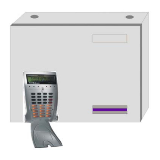
2.2.1 WALL MOUTING fig. 1 Fix the casing to the wall by means of 4 plastics dowels (8mm diameter) and apposite screws using the wall mounting holes indicated by the letters A, B, C and D. TP16-256 - Installer Manual Hardware... -
Page 20: Mains Connection
Connect the power supply unit to mains power by means of a double insulation cable (with insulation shielding) Once you have wired the mains cable to the proper terminal attach it to the control panel casing by means of the cable clamps included. Hardware Installer Manual - TP16-256... - Page 21 (blue wire) to the terminal N. Attach the cable to the casing by means of the cable clamps included. CONNECTION OF SECONDARY WINDING Wire the transformer secondary winding to the AC-IN terminals on the CPU board. TP16-256 - Installer Manual Hardware...
-
Page 22: Battery Connection
Use a battery with max. 12V-17Ah capacity. If mains connection is missing, the control panel will not work automatically if powered by battery only. For this, insert the jumper JP11 for some seconds, then remove it again. Hardware Installer Manual - TP16-256... -
Page 23: Cpu Board
The CPU board is devided into the following sections: Power supply (battery + transformer) Serial bus (2 RS485 ports + 1 TTL port for connection of the PC interface) Telephone In addition, the removable terminal board is connected through plug-in connection. TP16-256 - Installer Manual Hardware... -
Page 24: Serial Ports
(SPEED 4 or SPEED 8 STD). TTL port (on the CPU board). Permits the connection of an external multifunctional interface (PROG32 or PROG USB) for programming and monitoring by PC. Hardware Installer Manual - TP16-256... -
Page 25: Telephone Section
= line switched to the control panel (devices connected to the TEL terminals are inhibited) D17 (red) off = line not switched to the control panel D41 (yellow) blinking = follows the rings D41 (yellow) off = line on-hook TP16-256 - Installer Manual Hardware... -
Page 26: Terminal Board
NC / NA / BIL / B24 W ired zone 13 Input 13.8V DC Common input Output NC / NA / BIL / B24 W ired zone 14 Input 13.8V DC Positive voltage Output Hardware Installer Manual - TP16-256 2-10... - Page 27 4000 to 7400 rated 5400 Zone tamper alarm is viewed on the display of the console with indication of the zone violated. WARNING Zone tamper alarm is detected by double end-of-line resistor zones only. TP16-256 - Installer Manual Hardware 2-11...
-
Page 28: Input-Output Section
There are a series of terminals for the connection of the indoor and outdoor sirens. The terminal +14.4V provides the battery recharge voltage for the self-powered sirens. The terminal OFF- provides the stand-by status of the control panel. SELF-POWERED OUTDOOR SIRENS BY TECNOALARM +14.4V Positive voltage for recharge of the battery... - Page 29 WARNING For the correct functioning of the control panel with the sirens by Tecnoalarm the siren outputs +SRA and -SR INT have to be programmed with the normal functioning logic. LOGIC OUTPUTS There are 5 terminals for the logic outputs OFF-, OUT1+, OUT2-, TEC, PGM.
- Page 30 Hardware Installer Manual - TP16-256 2-14...
- Page 31 The inputs manage the RDV and Zone Bus detectors. Transformer on separate base ABS casing - size (L x H x D): 345 x 285 x 90mm Design by 1 Tamper switch against opening and wrenching TP16-256 - Installer Manual Input Expansion Modules - Hardware 2A-1...
- Page 32 The input section is connected to mains power through a special terminal. TRANSFORMER TA14 Mains input section (primary winding): 230V~ (red) Output section (secondary winding): 30V~ / 1,3A (blue) Frequency: 50/60Hz Power: 40VA Primary protection fuse: T 200mA Hardware - Input Expansion Modules Installer Manual - TP16-256 2A-2...
- Page 33 RS485 serial bus power supply 13.8V DC Output Input RS485 serial bus RS485 serial bus Output * NC (0 Ohm) - NA (superior to 2000 Ohm) - BIL (2000...4000 Ohm) - B24 (2000…4000 Ohm) TP16-256 - Installer Manual Input Expansion Modules - Hardware 2A-3...
- Page 34 ABS casing C90 or C100P (option) 2A.2.1 ELECTRONIC BOARD WARNING The jumper JP4 is needed for RS485 serial bus termination. It must be inserted on the last device connected in series only. Hardware - Input Expansion Modules Installer Manual - TP16-256 2A-4...
- Page 35 RS 485 s erial bus RS485 serial bus Output * NC (0 Ohm ) - NA (supe rior to 2000 Ohm ) - BIL (2000...4000 Ohm ) - B24 (2000… 4000 Ohm ) TP16-256 - Installer Manual Input Expansion Modules - Hardware 2A-5...
- Page 36 Plastic casing C90 or C100P (option) 2A.3.1 ELECTRONIC BOARD WARNING The jumper JP6 is needed for RS485 serial bus termination. It must be inserted on the last device connected in series only. Hardware - Input Expansion Modules Installer Manual - TP16-256 2A-6...
- Page 37 2A.4 INPUT EXPANSION SPEED 8 STD The expansion is composed of: Electronic board with 8 inputs The inputs DO NOT manage the RDV and Zone Bus detectors. Plastic casing (option) 2A.4.1 ELECTRONIC BOARD TP16-256 - Installer Manual Input Expansion Modules - Hardware 2A-7...
- Page 38 RS485 serial bus power supply 13.8V DC Output Input RS485 serial bus RS485 serial bus Output * NC (0 Ohm) - NA (superior to 2000 Ohm) - BIL (2000...4000 Ohm) - B24 (2000…4000 Ohm) Hardware - Input Expansion Modules Installer Manual - TP16-256 2A-8...
- Page 39 The expansion module is composed of: Electronic board with 8 inputs and 1.8A power supply Transformer on separate base ABS casing - Dimensions in mm: (L x H x D): 345x285x90 Tamper switch TP16-256 - Installer Manual Input Expansion Modules - Hardware 2A-9...
- Page 40 F1 of 200mA. The transformer kit is composed of: Input section (primary winding): 230V AC (red) Output section (secondary winding): 30V/1.3A (blue). Frequency: 50/60Hz Power: 40VA Fuse: F1 T 200mA Hardware - Input Expansion Modules Installer Manual - TP16-256 2A-10...
- Page 41 To connect a detector type MINIEXPLORER DOPPLER BUS having two separates parties, always use the two nearest inputs began to the impaire position (ex: inputs Z1 and Z2, or Z5, Z6 but never Z2 and Z3). TP16-256 - Installer Manual Input Expansion Modules - Hardware 2A-11...
- Page 42 To connect a detector type MINIEXPLORER DOPPLER BUS having two separates parties, always use the two nearest inputs began to the impaire position (ex: inputs Z1 and Z2, or Z5 and Z6 but never Z2 and Z3). Hardware - Input Expansion Modules Installer Manual - TP16-256 2A-12...
- Page 43 2A.7 INPUTS EXPANSION MODULE SPEED 4 PLUS The expansion module is composed of: Electronic board 4+4 inputs with memory cards Eeprom recording events ABS casing C90 or C100P (optional) Tamper switch 2A.7.1 ELECTRONIC BOARD TP16-256 - Installer Manual Input Expansion Modules - Hardware 2A-13...
- Page 44 S ens or bus Output S y nc hroniz ation M INIE XP LORE R B US S y nc hroniz ation Output * = de fa ult se ttings Hardware - Input Expansion Modules Installer Manual - TP16-256 2A-14...
- Page 45 1 micro against wrenching + 1 micro against opening C100P design by Dimensions (L x H x D): 260 x 160 x 60mm Tamper: 1 combined micro against wrenching and opening TP16-256 - Installer Manual Input Expansion Modules - Hardware 2A-15...
- Page 46 Hardware - Input Expansion Modules Installer Manual - TP16-256 2A-16...
- Page 47 10 seconds. LINE DISTURBED Interferences or serial bus is badly connected. The diagnostics are repeated approx. every 10 seconds alternately in Italian, French, LINE English, Spanish and German. DISTURBED TP16-256 - Installer Manual Console - Hardware 2B-1...
- Page 48 If there is only one console connected via serial bus and no other device, the jumper has to be inserted. 2B.1.2 DIP-SWITCH SETTINGS The SW1 dip-switch permits programming of the address of the modules on serial bus. There must not be two devices with the same address. Hardware - Console Installer Manual - TP16-256 2B-2...
- Page 49 The semitransparent label once you have written the program names on it must be delicately inserted by the slit in the lower part of the console, just above the hinges of the keypad protection lid. TP16-256 - Installer Manual Console - Hardware 2B-3...
- Page 50 Hardware - Console Installer Manual - TP16-256 2B-4...
- Page 51 2C. KEYPOINTS TP16-256 can be controlled by a total of 16 keypoints. Among the keypoints count all the secondary control units, i.e.: Electronic keypad TP SDN Reader of electronic keys with mini keypad TP SK6N Interface for electronic keys TP SKN 2C.1...
- Page 52 2C.2.2 ELECTRONIC BOARD The key reader with mini keypad is protected by a combined tamper switch against opening of the casing and detachment of the casing from the wall by unauthorized personnel. Hardware - Keypoints Installer Manual - TP16-256 2C-2...
- Page 53 If the opposite example of connection has been followed, the LED on the key reader assume the following meaning: WARNING If all the LED are blinking, the serial bus is missing or connected incorrectly. TP16-256 - Installer Manual Keypoints - Hardware 2C-3...
- Page 54 2C.5 DIP-SWITCH SETTINGS The SW1 dip-switch permits programming of the address of the modules on serial bus. There must not be two devices with the same address. Hardware - Keypoints Installer Manual - TP16-256 2C-4...
- Page 55 The output expansion module ESP32-OCN permits to extend the outputs of the control panel providing supplementary system status signaling. The output expansion module must be connected via serial bus RS485 and configurated by dip-switch SW1. 2D.1.1 ELECTRONIC BOARD 2D.1.2 CASING TP16-256 - Installer Manual Output Expansion Modules - Hardware 2D-1...
- Page 56 The end-of-serial-bus jumper is to be inserted on the last device connected in series only. 2D.4 DIP-SWITCH SETTINGS The SW1 dip-switch permits programming of the address of the modules on serial bus. There must not be two devices with the same address. Hardware - Output Expansion Modules Installer Manual - TP16-256 2D-2...
-
Page 57: Led Blinking Slowly Led Blinking Quickly Led On Led Off
Program prealarm active (entry time running) Led on Program alarm stored (alarm memory) Led off Program in stand-by ADDRESS 3 PROGRAM STAND-BY Led on Program disarmed (stand-by) Led off Program armed TP16-256 - Installer Manual Output Expansion Modules - Hardware 2D-3... -
Page 58: Address 4
Led on Remote control active Led off Remote control deactivated ADDRESS 5 GENERAL ALARMS AND SYSTEM STATUS Led on Alarm or status active Led off Alarm or status not active Hardware - Output Expansion Modules Installer Manual - TP16-256 2D-4... - Page 59 ADDRESSES 6 TO 13 TP16-256 - Installer Manual Output Expansion Modules - Hardware 2D-5...
- Page 60 ZONE ALARM OR ZONE TAMPER ALARM Led on Alarm active Led off No alarm ADDRESS 14 INDOOR SIREN STATUS Led on Siren active Led off Siren deactivated (stand-by) Hardware - Output Expansion Modules Installer Manual - TP16-256 2D-6...
- Page 61 For expert programming you should preferably use the addresses 17 to 32. ADDRESSES 17 TO 32 - RESERVED FOR EXPERT PROGRAMMING TP16-256 - Installer Manual Output Expansion Modules - Hardware 2D-7...
- Page 62 It is possible to add a cloned module only if a standard (uncloned) module with the same address has been installed because the control panel never sees a cloned module on serial bus. Hardware - Output Expansion Modules Installer Manual - TP16-256 2D-8...
- Page 63 The connection with the PC is made by means of a standard 9-wires serial cable whereas for the connection with the control panel a 10-wires TTL telephone cable is used. WARNING Connect the programming interface to the control panel first, and only then to the PC. TP16-256 - Installer Manual Programming Interfaces - Hardware 2E-1...
- Page 64 The connection with the PC is made by means of either a standard USB cable or, if not used for any control panel, a standard 9-wires serial cable. For the connection with the control panel TP16-256 a 10-wires TTL telephone cable is used. The other ports are reserved for the connection of different types of Tecnoalarm devices.
- Page 65 If the button has been pressed unwillingly, to return to normal functioning without losing firmware programming of the control panel, press S1 again. The PROG led is switched off. TP16-256 - Installer Manual Programming Interfaces - Hardware...
- Page 66 SPEED RS485. The jumpers W1 to W4 and W6 are reserved to the Tecnoalarm staff and must not be used. They must all be removed. Consider that an improper use of the jumpers may cause malfunctioning of the serial bus RS485.
- Page 67 2E.3.2 CASING WARNING The serial bus extension module SPEED RS485 has to be mounted inside the casing TKBOX/A using the plastic spacers included. TP16-256 - Installer Manual Programming Interfaces - Hardware 2E-5...
- Page 68 Hardware - Programming Interfaces Installer Manual - TP16-256 2E-6...
- Page 69 The jumper JP1 for end of RS485 serial bus must only be inserted on the last device connected via serial bus. For functioning with the TP16-256 control panel, the TECNOCELL-PRO PL must communicate at 38,400 bps via serial bus, therefore insert the H.SPEED jumper.
- Page 70 Hardware - Telephone Communicator with GSM Module Installer Manual - TP16-256 2F-2...
- Page 71 Blinking if communication via RS485 serial bus OK LED DL3 (RED) - MASK Lit in case of masking LED DL4 (GREEN) - RX Blinking during data reception LED DL5 (GREEN) - POWER Lit if power dupply OK TP16-256 - Installer Manual Wireless Expansion Modules - Hardware 2G-1...
- Page 72 868MHZ SECTION The 868MHz wireless receiver section can be enabled and disabled by the jumper W2: Jumper inserted = 868MHz section enabled Jumper removed = 868MHz section disabled 2G.1.5 CASING Hardware - Wireless Expansion Modules Installer Manual - TP16-256 2G-2...
- Page 73 Blinking if communication via RS485 serial bus OK LED DL2 (RED) - MASK Lit in case of masking LED DL3 (GREEN) - RX Blinking during data reception LED DL4 (GREEN) - POWER Lit if power supply OK TP16-256 - Installer Manual Wireless Expansion Modules - Hardware 2G-3...
- Page 74 2G.2.2 DIP-SWITCH SW1 SETTINGS TABLE 2 2G.2.3 CASING Hardware - Wireless Expansion Modules Installer Manual - TP16-256 2G-4...
- Page 75 Close the plastic shells again and pull the screw tight BATTERY TYPE Use batteries with the following features: Type number: CR2032 (Brands: Maxell, Energizer, Varta, Sony, Renata) Type: Lithium (Li/MnO Voltage: Capacity: 220mAh TP16-256 - Installer Manual Wireless Expansion Modules - Hardware 2G-5...
- Page 76 LED on Alarm memory PLASTIC LID DISPLAY Views date/time or active parameter BUTTON FOR OPENING OF THE LID KEYPAD LABEL Recapitulation of the principal commands PLASTIC LID SUMMARY OF COMMANDS Hardware - Wireless Expansion Modules Installer Manual - TP16-256 2G-6...
- Page 77 2G.4.1 ELECTRONIC BOARD 2G.4.2 DIP-SWITCH SETTINGS TP16-256 - Installer Manual Wireless Expansion Modules - Hardware 2G-7...
- Page 78 Verify siren sounding by arming the control panel and violating a zone Close the cover Quit the maintenance mode on the control panel and check end of the low battery signaling Hardware - Wireless Expansion Modules Installer Manual - TP16-256 2G-8...
- Page 79 DIPSWIT CH 2 = O N - FUNCT IO NING LEVEL C Loca l sound signa l a fte r 2 hours of inte rruption of com m unica tion w ith the control pa ne l TP16-256 - Installer Manual Wireless Expansion Modules - Hardware...
- Page 80 Hardware - Wireless Expansion Modules Installer Manual - TP16-256 2G-10...
-
Page 81: Draft Of The Installation On Paper
3. SET-UP The control panel TP16-256 can be programmed using either a console with liquid crystal display or a PC equipped with the Tecnoalarm programming and monitoring software. Programming by PC can be made at distance via telephone line or on the spot connecting the PC to the control... - Page 82 Type of installation (burglary, home, burglary general, telephone communicator, medical aid, technical, fire protection, industrial, red, yellow, green and blue) ID (ID code of the installation) The ID code is a 4-digits code (0000 to 9999) used by the Set-up Installer Manual - TP16-256...
- Page 83 Then open the hardware configuration window by clicking on the opposite icon. On the screen is viewed the installation composed of merely the CPU board (default) without expansion modules nor console: TP16-256 - Installer Manual Set-up...
- Page 84 Backup (saving of the data relating to the wireless section) Restore (recovery of the data relating to the wireless section) Opening message Transmission and listening of the opening message Firmware/vocabulary upgrade Upload of the new firmware and vocabulary versions Set-up Installer Manual - TP16-256...
- Page 85 Comparison of the hardware programmed by PC with the devices connected and viewing of coherence and incoherence. RSC system analysis Analysis of the communication with the Sensor Bus devices and viewing of the attempts at connecting and the quantity of communication errors for every single device TP16-256 - Installer Manual Set-up...
- Page 86 Set-up Installer Manual - TP16-256...
-
Page 87: Addition Or Deletion Of Modules
If you confirm the addition of the module, it is added to the system configuration viewed. The console is added to the system configuration viewed. Next to the module the dipswitch address is shown. TP16-256 - Installer Manual Set-up... - Page 88 Key interface permitting the connection of key readers for the control of maximum 3 programs. RSC input expansion modules SPEED 8 PLUS Provides 4 bus conector for connection of 8 detectors Bus SPEED 4 PLUS Provides 2 bus conector for connection of 4 detectors Bus Set-up Installer Manual - TP16-256...
- Page 89 Provides 32 signaling leds associated to the zone and tamper alarms of the zones (1 to 32) - address 6 SINOTTICO 32N (fixed led configuration) Provides 32 signaling leds associated to the zone and tamper alarms of the zones (33 to 64) - address 7 TP16-256 - Installer Manual Set-up...
-
Page 90: Installation
SAEL 2000 WL Bidirectional wireless siren TX240-3 Wireless key with 3 function keys transmitting with rolling code. TP16-256 distinguishes up to 60 wireless keys. INSTALLATION 3.3.1 CONNECTION OF THE MODULES VIA SERIAL BUS RS485 Once you have configurated and physically installed the hardware (i.e. expansion modules, consoles, detectors, sirens etc.) procede with wiring of the devices to the CPU board. - Page 91 TP16-256 - Installer Manual Set-up 3-11...
-
Page 92: Programming Of The Addresses Of The Modules
The Tecnoalarm programming and monitoring software assigns the addresses automatically according to the order in which they are added to the hardware configuration and taking into account all the necessary limitations. -
Page 93: Zone Configuration
Permits the creation of a list of zones freely associated to the zone inputs of the hardware installed as well as their configuration. Open the zone configuration tables by clicking on the opposite icon. TP16-256 - Installer Manual Programming by PC... -
Page 94: Zone List And Zone Parameters
ZONE LIST AND ZONE PARAMETERS If necessary, select the zone parameter window by clicking on the tab Zone. TP16-256 controls a total of 256 zones. The zones can be associated freely to the zone inputs provided by the hardware installed: CPU board (minimum configuration) providing 16 zone inputs max. - Page 95 Type permits the selection of the modell of the device Filter determines the response time or sensitivity according to the kind of the detector or contact selected Commands available to confirm and close the window Abort to undo the settings TP16-256 - Installer Manual Programming by PC...
- Page 96 It is possible to program the description manually writing directly in the zone description line. Remember that the display of the console is able to view descriptions of maximum 16 characters. All further characters will be cut off. Programming by PC Installer Manual - TP16-256...
- Page 97 Repeat the procedure for every zone to be configured (up to a total of 256). Once all the zones have been configured, press: to confirm and close the zone configuration tables Abandon to cancel the zone parameters entered TP16-256 - Installer Manual Programming by PC...
- Page 98 Repeat the procedure for every zone to be configured (up to a total of 256). Once all the zones have been configured, press: to confirm and close the zone configuration tables Abandon to cancel the zone parameters entered Programming by PC Installer Manual - TP16-256...
-
Page 99: Zone-Function Association
The zones checked are associated to the group of common zones and are included in several programs each. As a consequence, they are enabled for the detection of alarms only if all the programs they are included in are armed. TP16-256 - Installer Manual Programming by PC... - Page 100 The zones that are not included in the programs armed, are not enabled for the detection of alarms, exception made of the technical, hold-up and tamper zones that are always enabled even if the system is completely disarmed. The control panel TP16-256 permits the creation of maximum 32 programs, every program can be composed of maximum 256 zones.
-
Page 101: Consoles
Abandon to undo the zone-program association 4.1.4 CONSOLES Open the zone configuration tables and select the console configuration window by clicking on the tab Keypads. On the screen is viewed: TP16-256 - Installer Manual Programming by PC... - Page 102 The code for deactivation are: none Privileged user code Master code Installer code Once you have configured the consoles, press: to confirm and close the zone configuration tables Abandon to undo the configuration of the consoles Programming by PC Installer Manual - TP16-256 4-10...
-
Page 103: Keypoints
TP SKN pilots only 3 leds. By default the leds are always associated to the first programs of the system. To associate a led to a determined program, click on the arrow next to the program number and select the program (1 to 32) to be associated. TP16-256 - Installer Manual Programming by PC 4-11... -
Page 104: System Options
The buzzer is active during the time automatic arming is displayed (arming by timer). Sound report Permits enabling/disabling of the voice report by the consoles. If enabled, the above operating conditions are accompagnied by a voice message. Programming by PC Installer Manual - TP16-256 4-12... - Page 105 To select the logic siren click on the arrow next to the inscription Siren 1 and scroll the siren list (1 to 32). Programmable logic output PGM To associate the output to the programs check the item beneath the program number. TP16-256 - Installer Manual Programming by PC 4-13...
- Page 106 To enable an option, click on the box beside it. Once you have set the system options, press: to confirm and close the zone configuration tables Abandon to undo the system option settings Programming by PC Installer Manual - TP16-256 4-14...
-
Page 107: Outputs
Indoor siren 11 Outdoor siren 5 Outdoor siren 31 Remote control 9 Program 19 Indoor siren 12 Outdoor siren 6 Outdoor siren 32 Remote control 10 Program 20 Indoor siren 13 Outdoor siren 7 TP16-256 - Installer Manual Programming by PC 4-15... -
Page 108: Bus Sirens
Permits to select the bus sirens (1 to 15) and defines its functions. PROGRAM Permits the association of the bus sirens selected to the arming programs of the control panel (1 to 32). Programming by PC Installer Manual - TP16-256 4-16... - Page 109 Sounding and falshing light are actived To enable an option, click on the box beside it. Once all the options required have been enabled, press: to confirm and quit Abandon to quit without saving TP16-256 - Installer Manual Programming by PC 4-17...
-
Page 110: Configuration Of The Telephone Section
During the digital communications the control panel transmits/receives data regarding alarms and system status using a special protocol developped by Tecnoalarm or one of the most common digital transmission formats. Programming is made using the digital Tecnoalarm protocol. - Page 111 (max. 15 digits). Format The protocol for callback communications is unchangeable, i.e. digital Tecnoalarm format (00 Tecnoalarm). Disable redirection The redirection of callback permits the execution of return calls to a telephone number different from those entered in the telephone configuration window.
- Page 112 WARNING The digital non-Tecnoalarm protocols are to devide in single type and multiple type protocols. In any case, both if a single type protocol is programmed or not, the other events are transmitted. No event will be lost due to the communicator block! Single type protocols transmit one event at a time, i.e.
- Page 113 Upon reception of the blocking command the active call is nterrupted and the alarm call cycles of both the active and all the other digital Tecnoalarm channels programmed for the event are blocked. The communicator block affects all the telephone channels independently from the protocol they use.
-
Page 114: Telephone Communicator With Gsm Module
Check the item to enable the emergency SMS and enter the message to be transmitted. SMS heading The SMS alarm message can be preceded by a header preceding the SMS message. Programming by PC Installer Manual - TP16-256 4-22... -
Page 115: Report Codes
Enable guided menu (terminal S) The control panel TP16-256 composes the voice messages itself with the help of the onboard vocabulary and communicates it together with telephone number to send the message to via S-wire (speaker terminal on the CPU board) to the telephone communicator with GSM module. Guided menu supported voice messages are more detailed than with those residing on the SIM of the GSM module. -
Page 116: Opening Message - Vocabulary
The opening message is a voice message that is reproduced during every outgoing telephone call. It can be recorded by the user in different ways: using the Tecnoalarm programming and monitoring software, a special sound manager resident on your PC, loading from a prerecorded WAV file or by telephone. - Page 117 Press the Vocabulary button in the lower part of the window. The English vocabulary can be found in the following directory C:\Program files\Tecnoalarm\Centro\WAV2\ENG Select the file Msg_cnf.tcn. Once you have finished programming of the opening message and set the language of the vocabulary, press:...
-
Page 118: Remote Controls
Once you have finished the association of descriptions to the remote controls, press: to confirm and close the telephone configuration tables Abandon to cancel the descriptions entered and close the telephone configuration tables. Programming by PC Installer Manual - TP16-256 4-26... -
Page 119: Configuration Of The Time Parameters
Access periods Customization of the biannual calendar SELECTION OF THE PROGRAM Select the program (or all programs) your are referring to by clicking on the program item and scrolling down the list. TP16-256 - Installer Manual Programming by PC 4-27... -
Page 120: Time Settings
Once you have finished programming of the time parameters press: to confirm and close the time configuration tables Abandon to undo programming and close the time configuration tables Programming by PC Installer Manual - TP16-256 4-28... -
Page 121: Timers
Qualified arming (avoid arming in the presence of low battery, power failure, tamper, supervision, fault and antimasking alarm). TP16-256 - Installer Manual Programming by PC 4-29... - Page 122 Once you have finished programming of the timers and the test call cycle, press: to confirm and close the time configuration tables Abandon to undo programming and close the time configuration tables Programming by PC Installer Manual - TP16-256 4-30...
-
Page 123: Access Periods
Every working day Every holiday-eve Every holiday Every sunday Every saturday Deactivation time To program the deactivation time of the access period, select the item next to the frequency and enter the time (hh:mm). TP16-256 - Installer Manual Programming by PC 4-31... - Page 124 Once you have finished the configuration of the access periods and the association to the codes and keys, press: to confirm and close the time configuration tables Abandon to undo programming and close the time configuration tables Programming by PC Installer Manual - TP16-256 4-32...
-
Page 125: Customization Of The Calendar
A crossed sun will be shown next to the date. Subsequently select Winter time and click once on the day of end of summer time. A sun will be shown next to the date. TP16-256 - Installer Manual Programming by PC 4-33... - Page 126 Repeat the procedure for the second year (Customization 2nd year). Once you have finished programming of the biannual calendar, press: to confirm and close the time configuration tables Abandon to undo programming and close the time configuration tables Programming by PC Installer Manual - TP16-256 4-34...
-
Page 127: Programming Of The Codes, Keys And Wireless Keys
(arming/disarming or by-pass) Code length The code length is relevant for all the codes of the system. The control panel accepts 4 to 6-digits codes. The default code length is 5 digits. TP16-256 - Installer Manual Programming by PC 4-35... - Page 128 Exclusion disabled If checked, the user will not be entitled to arm the control panel excluding some of the zones (both voluntary and automatic zone exclusion are disabled). The control panel Programming by PC Installer Manual - TP16-256 4-36...
-
Page 129: Programming Of The Keys
The key will only be enabled to act on (arm/disarm or partset) the programs associated (1 to 32). To associate a program to the key click on the corresponding item. The program number will be shown as a confirmation of the association. TP16-256 - Installer Manual Programming by PC 4-37... - Page 130 Repeat the procedure for all the keys (1 to 64). Once you have finished programming of the keys, press: to confirm and close the code configuration tables Abandon to undo programming and close the code configuration tables Programming by PC Installer Manual - TP16-256 4-38...
-
Page 131: Programming Of The Wireless Keys
TP16-256 - Installer Manual Programming by PC 4-39... - Page 132 Repeat the procedure for all the wireless keys (1 to 60). Once you have finished programming of the wireless keys, press: to confirm and close the code configuration tables Abandon to undo programming and close the code configuration tables Programming by PC Installer Manual - TP16-256 4-40...
-
Page 133: Configuration Of The Wireless Sirens And Consoles
Volume of sounding for alarm or technical alarm is always set at the maximum. Siren mode The siren can be programmed so as to work either as an indoor or an outdoor siren. TP16-256 - Installer Manual Programming by PC 4-41... -
Page 134: Configuration Of The Wireless Consoles
The control panel administers up to 4 wireless consoles individually programmable with the following parameters: Association of the programs to the LED of the consoles Programming of the attributes of the consoles SELECTION OF THE CONSOLE Select the corresponding item and scroll down the list. Programming by PC Installer Manual - TP16-256 4-42... - Page 135 Repeat the process for all the wireless consoles (1 to 4). Once you have finished the configuration of the wireless consoles, press: to confirm and close the wireless configuration tables Abandon to undo programming and close the wireless configuration tables TP16-256 - Installer Manual Programming by PC 4-43...
-
Page 136: Access To The Advanced Programming Level
To enable the advanced programming level, click on the item Advanced. Subsequently open the advanced programming configuration tables by clicking on the opposite icon. WARNING For the description of the commands and programming examples see the appendix C Advanced programming. Programming by PC Installer Manual - TP16-256 4-44... -
Page 137: Saving Of System Configuration
(2). Click on the house symbol (3) to open the system configuration. On the screen is viewed the complete hardware configuration of the system selected: TP16-256 - Installer Manual Programming by PC 4-45... - Page 138 Upload of the complete system configuration. Start uploading (changes only) Upload of the changes (only if system configuration has been sent to the control panel before using the same PC). Press the appropriate key. Programming by PC Installer Manual - TP16-256 4-46...
- Page 139 If you have to reset the control panel for some reason (e.g. for firmware upgrade) in order to avoid losing the codes and keys programmed, and being obliged to reprogram them afterwards manually, download the system configuration before you reset the control panel, then send (upload) the system configuration. TP16-256 - Installer Manual Programming by PC 4-47...
-
Page 140: Indicators Of System Configuration Coherence
Once the download has been completed correctly, system configuration is available and viewed in the local programming window. The indicators 1 (local programming window) and 4 (control panel) should then have the same colour. Programming by PC Installer Manual - TP16-256 4-48... -
Page 141: Preliminary Remarks
5. PROGRAMMING BY CONSOLE WARNING Programming of the control panel is only possible by PC using the Tecnoalarm programming software or LCD console (LCD300/S). The secondary control units (indicated as keypoints) do not permit programming. To program the control panel by console enter the installer programming menu by - ACCESS - entering the installer code (default code 54321) on the console. - Page 142 If you deny (by pressing the *NO key), the description will only be used as voice message. N.B. The display can view descriptions of maximum 16 digits, all further character will be cutoff. The descriptions can be modified manually only by PC. Programming by Console Installer Manual - TP16-256...
-
Page 143: Programming Sequence
19) Module-zone exclusion (Menu 18) Paragraph 5.21 20) Control panel checkup (Menu 19) Paragraph 5.22 ATTENTION While a console is in use, all the other consoles of the system are disabled and view Waiting. TP16-256 - Installer Manual Programming by Console... -
Page 144: Zone Configuration
5.3.2 INPUT-ZONE ASSOCIATION (CREATION OF THE ZONE LIST) Zone 001 TP16-256 controls a total of 256 zones freely associable to the physical zone inputs Ass. inputs provided by the hardware installed:... -
Page 145: Definition Of The Zone Type
Hold-up zone The zone is always enabled (even if the control panel is disarmed). It releases a silent alarm (no alarm visual nor acoustic alarm signaling) with maximum priority. TP16-256 - Installer Manual Programming by Console... -
Page 146: Definition Of The Contact Type (For Wired Zones Only)
NC (normally closed) NO (normally open) ZBUS (zone bus by Tecnoalarm) - relevant for the inputs of the expansion modules 1 to 32 only, not for the CPU board SBUS (sensor bus by Tecnoalarm) - relevant for the inputs of the expansion... - Page 147 Settings: very sensitive, sensitive, normal, hard, very hard. • MW filter Defines the duration time of the microwave. Settings: 100, 300, 500 milliseconds or 1 second. • Pulses IR Settings: 1 or 3 TP16-256 - Installer Manual Programming by Console...
- Page 148 1x Ta - Lower Beams (1,2) Tax8 • Ta time [ # ] Signaling active Signaling not active • MASK time Defines the delay of release of antimasking alarm Settings: disabled, 3 sec., 30 sec., 120 sec. Programming by Console Installer Manual - TP16-256...
-
Page 149: Definition Of The Alarm Cycles
Error correspond to the device type programmed (e.g. IrR programmed but contact learnt). In case of error, quit by pressing the EXIT key and re-enter the learning menu, then repeat the entire procedure. TP16-256 - Installer Manual Programming by Console... -
Page 150: Activations
Siren mode Defines the functioning mode of the siren, i.e. indoor or outdoor siren Alarm Defines the siren activation mode for alarm (not active, sounding, flashing, sounding+flashing) Prealarm Programming by Console Installer Manual - TP16-256 5-10... -
Page 151: Configuration Of The Wireless Consoles
No wireless console has been associated yet to the position selected (1...4). [ # ] Console associated A wireless console has already been associated to this position. WARNING The procedure of learning of wireless devices is explained in the paragraph 5.3.7. TP16-256 - Installer Manual Programming by Console 5-11... -
Page 152: Programming Of The Serial Number Of The Control Panel
The serial number of the control panel is used in every communication with the sirens Wireless and the wireless receivers-transmitters. It is to avoid interferences with other wireless Sn. Ctrl panel systems placed near TP16-256. Commands available + #YES to view the serial number programmed + 1...9... -
Page 153: Configuration Of The Programs
The control panel TP16-256 permits the creation of maximum 32 programs, every program can be composed of maximum 256 zones. -
Page 154: Programming Of The Functions
The zone viewed has already been associated to the program selected. Commands available + #YES to associate the zone viewed to the function + *NO to cancel a possible existing association + EXIT to accept programming and quit the submenu Programming by Console Installer Manual - TP16-256 5-14... -
Page 155: Programming Of The Time Parameters
Antimasking alarm is released if the control panel captures an interference having Time the same frequency as that of the wireless devices associated and persisting for Antimasking a preset period of time. The antimasking filter defines an additional delay the TP16-256 - Installer Manual Programming by Console 5-15... -
Page 156: Programming Of The Outputs
The buzzer sounds during the alarm time. Warn. by-pass (end-of-by-pass warning) The buzzer sounds while the end-of-by-pass warning is displayed. Buzzer Warn. autom. Alarm The buzzer sounds while the warning of imminent automatic arming (by timer) is displayed. Programming by Console Installer Manual - TP16-256 5-16... -
Page 157: Configuration Of The Programmable Outputs
+ EXIT to accept programming and quit the submenu 5.9.4.2 PROGRAMMING OF THE MEANING OF THE LOGIC OUTPUTS According to programming, the logic outputs assume the following meanings: TP16-256 - Installer Manual Programming by Console 5-17... -
Page 158: Configuration Of The Bus Sirens
(observing the relative time settings) and in case of general alarm (tamper, trouble etc.). Sound type available: Sound 1 - Bidirectional sweep tone (default setting) Sound 2 - Monodirectional sweep tone Sound 3 - Bitone Programming by Console Installer Manual - TP16-256 5-18... -
Page 159: Programming Of The Timers
(i.e. always or only if the control panel is armed) Begin. time Defines the starting hour of the test call cycle Commands available Test call + yw to select the parameter Begin. time [ + #YES to confirm the selection TP16-256 - Installer Manual Programming by Console 5-19... -
Page 160: Configuration Of The Timers
Remote deactivat. Deactivation of the remote control/s associated Ctrl Arming Arming with alarm check Commands available + yw to select the item + #YES to confirm the selection + EXIT to accept programming and quit the submenu Programming by Console Installer Manual - TP16-256 5-20... -
Page 161: Programming Of The Access Periods
Permits programming of the frequency of activation of the access period selected: Hour beg. Deactivated Holiday-eve Monday Thursday Every day Holiday Tuesday Friday Period 01 Working day Sunday Wednesday Saturday Hour end TP16-256 - Installer Manual Programming by Console 5-21... -
Page 162: Programming Of The Remote Controls
Chime Enabling of the chime function Volume Permits volume adjustment for the voice report at 4 different settings (mute, low, medium, high) Programming by Console Installer Manual - TP16-256 5-22... -
Page 163: Configuration Of The Keypoints
It is very important that in addition to the program-keypoint association you have defined the keys to control the programs associated to the keypoint in question. If this is not the case, the key will not be recognized on its insertion. TP16-256 - Installer Manual Programming by Console 5-23... -
Page 164: Configuration Of The Wireless Keys
[ # ] Attribute has been associated to the wireless key selected Commands available + #YES to associate the function to the wireless key + *NO to cancel an existing association + EXIT to confirm and quit Programming by Console Installer Manual - TP16-256 5-24... -
Page 165: Learning Of The Wireless Key
If there are not or a single type protocol has been programmed, it closes the communication and blocks the active phone call cycle of this channel. In all the other cases, the next event is transmitted. TP16-256 - Installer Manual Programming by Console 5-25... - Page 166 Block all the channels Rings Digit. block Interruption of all the active digital calls using non Tecnoalarm protocols. On reception of the blocking command, the control panel can: Block the single channel On reception of the blocking command, the control panel checks if there are events queued up.
-
Page 167: Pabx Number
For digital data transmission, it is necessary to define a digital protocol according to the kind of device (Tecnoalarm or Telephone non-Tecnoalarm device) connected to and the ID code. The system is compatible with Channel F the most commonly used digital protocols (see table). -
Page 168: Programming Of The Callback Numbers
+ EXIT to accept programming and quit the submenu WARNING By default the channels are set for the digital transmission protocol Tecnoalarm (000). 5.15.4 PROGRAMMING OF THE CALLBACK NUMBERS Telephone The callback function is indispensable for remote programming of the control panel. -
Page 169: Configuration Of The Gsm Module
Enab. digit Enab.digit Permits enabling of the digital data channel (not to be used if the GSM telephone communicator is used as a back up device) [ # ] Digital data channel enabled TP16-256 - Installer Manual Programming by Console 5-29... -
Page 170: General Notes On Sms
The SMS are always composed of a heading (introductory frase) containing general information and the event description. A typical heading would be "Control panel TP16-256 Tecnoalarm”. The event description is identical with that stored in the event log, e.g. “Arming Program 1 [perimeter]“. -
Page 171: Association Of The Events To The Channels
D + #5 to insert the character E + #6 to insert the character F + 0...9 to insert number values + EXIT to accept programming and quit the submenu TP16-256 - Installer Manual Programming by Console 5-31... -
Page 172: Program Related Events
Options Signaling AM (enabling of antimasking alarm signaling) Signaling AM Permits enabling/disabling of antimasking alarm signaling through the consoles, supervisory boards and output expansion modules. [ # ] Antimasking alarm signaling enabled Programming by Console Installer Manual - TP16-256 5-32... - Page 173 ] Option not enabled [ # ] Option enabled Commands available + #YES to enable the option selected + *NO to disable the option selected + EXIT to accept programming and quit the submenu TP16-256 - Installer Manual Programming by Console 5-33...
-
Page 174: Programming Of The Codes
#(hash) key, but is obliged to select them manually. Privileged Defines the code as privileged. In addition to the standard functions, the user will Programming by Console Installer Manual - TP16-256 5-34... -
Page 175: Programming Of The Standard User Codes
(see § 5.17) is disabled. If the user code modification is enabled, the holders of the standard user codes will be entitled to change their own codes and the master code will no longer have access to programming of the code values. TP16-256 - Installer Manual Programming by Console 5-35... -
Page 176: Programming Of The Keys
Learning of the electronic keys requires the master code. In addition, it requires a console with liquid crystal display (LCD300/S) and a key reader with mini keypad (TP SK6N). DELETION OF AN EXISTING WIRELESS KEY To delete an existing association, press the star key (*NO). Programming by Console Installer Manual - TP16-256 5-36... -
Page 177: Activation/Deactivation Of The Remote Controls
[ # ] Device or zone excluded Commands available + #YES to exclude the selected device + *NO to enable the selected device + EXIT to accept programming and quit the submenu TP16-256 - Installer Manual Programming by Console 5-37... -
Page 178: Test
(S1, S2, S3 and S4): Communication (TX/RX) without errors Yes Yes --- Communication (TX/RX) with negative issue - - - No wireless siren associated to this position Commands available + EXIT to quit the submenu Programming by Console Installer Manual - TP16-256 5-38... -
Page 179: Zone Test
WARNING During the test, the wireless outdoor sirens work according to programming (see § 5.4), i.e. not active, sounding, flashing, sounding+flashing. The sounding or flashing time, however, is irrelevant. TP16-256 - Installer Manual Programming by Console 5-39... -
Page 180: Viewing Of The Firmware Version
Ver. 1.5 Commands available + EXIT to quit the submenu WARNING During the test, the GSM telephone communicator must be connected to the control panel through the serial line. Programming by Console Installer Manual - TP16-256 5-40... - Page 181 1 master code (default code 12345) The master code is usually reserved for the owner of the system and gives access to the master programming menu as well as the standard arming/disarming and parset functions. TP16-256 - Installer Manual Control by Console...
- Page 182 The modification of the standard user codes is subject to enabling by the installer. If the master is not enabled for the management of the standard user codes, it will permit only viewing and and modification of itself. Control by Console Installer Manual - TP16-256...
- Page 183 200 standard user codes (default code 00000) Every code can be enabled singularly for arming/disarming or partset of determined programs. TP16-256 - Installer Manual Control by Console...
- Page 184 OPERATIONS WITHOUT CODE Control by Console Installer Manual - TP16-256...
-
Page 185: Arming
The 15 pairs of program LED (yellow and red) by default are associated to the first 15 programs of the control panel. The installer can associate the LED of every single console to any of the 32 programs. TP16-256 - Installer Manual Control by Console... -
Page 186: Arming With Master Code
Program x Select the zones to be excluded pressing: + yw to select the zones to be excluded Control by Console Installer Manual - TP16-256... -
Page 187: Arming With Standard User Code
The programs that are already armed and those the standard user code in question is not enabled for are not influenced. To abort arming of the programs selected press the EXIT key. The process is aborted and the control panel returns to stand-by. 6.1.2.1 TOTAL ARMING See § 6.1.1.3 TP16-256 - Installer Manual Control by Console... -
Page 188: Quick Arming (If Enabled)
It is always executed even in presence of trouble/general alarm or fault (low battery, power failure etc.). ABORT OF AUTOMATIC ARMING Automatic arming can be aborted in the following way: > Enter the master code > Select the timer menu > Select the timer to be blocked Control by Console Installer Manual - TP16-256... -
Page 189: Arming During The Access Periods
+ *NO to disarm all the programs The yellow LED corresponding to the programs disarmed are switched off and the control panel returns to stand-by. TP16-256 - Installer Manual Control by Console... -
Page 190: Disarming With Standard User Code
Outside the access periods associated the codes are not accepted by the control and any attempt at acceding to the system will have no effect. When trying to do so, on the display is viewed ACCESS ! DENIED !. Control by Console Installer Manual - TP16-256 6-10... -
Page 191: By-Pass
At the time and for the period of time programmed by the installer on the display is Automatic viewed a warning of imminent automatic arming and blink the yellow program LED on the console. According to programming, the buzzers of the consoles are activated, too. TP16-256 - Installer Manual Control by Console 6-11... -
Page 192: Deactivation Of By-Pass On Expiry Of Maximum By-Pass Time
The blocking command stops all the active alarm calls cycles as well as those waiting. The block of the telephone calls is not permitted in case of hold-up alarm. In this case, the cycle continues uninterrupted. Control by Console Installer Manual - TP16-256 6-12... -
Page 193: Viewing Of The Event Buffer
Answer with confirmation - all events confirmed Answer Answer ok M. answ. ko Answer without confirmation - no event confirmed - GSM WARNING The events cannot be deleted from the event buffer. TP16-256 - Installer Manual Control by Console 6-13... -
Page 194: Reset Of Led Signaling
The active alarms are not stopped upon reset of alarm memory signaling. LED signaling for tamper and general alarm (e.g. low battery, power failure) cannot be reset by the user. Consult the installer. Control by Console Installer Manual - TP16-256 6-14... -
Page 195: Release Of Panic Alarm
Zone 2 Viewing of alarm of a specific program To view the stored alarms of a specific alarm, preced the MEM key with the program Viewing number, e.g.: Program 1 + 1 MEM TP16-256 - Installer Manual Control by Console 6-15... - Page 196 Control by Console Installer Manual - TP16-256 6-16...
-
Page 197: Control By Tp Sk6N Key Reader With Mini Keypad
The common zone (entrance), however, is activated only if the programs of both appartments it is included in are armed simultaneously. TP16-256 - Installer Manual Control by Keypoint... - Page 198 To abort arming of the programs selected press the key F3. The process is aborted and the control panel returns to stand-by. EXIT TIME The zones defined as delayed, upon arming observe the exit time programmed by the installer. Control by Keypoint Installer Manual - TP16-256...
-
Page 199: Disarming
It is possible to define up to 8 access periods of the electronic keys. As a consequence, the electronic keys are enabled for by-pass during the access periods associated by the installer or the holder of the master code only. TP16-256 - Installer Manual Control by Keypoint... -
Page 200: Release Of Panic Alarm
The common zone (entrance), however, is activated only if the programs of both appartments it is included in are armed simultaneously. Control by Keypoint Installer Manual - TP16-256... - Page 201 WARNING On arming of a program in presence of open zones, the alarm devices programmed (sirens/logic outputs/telephone channels) are activated unless the open zones are exluded with a procedure explained lateron. TP16-256 - Installer Manual Control by Keypoint...
-
Page 202: Disarming
7.2.2.1 SINGLE ARMING Introduce an electronic key enabled for the program armed into the key reader. The program is disarmed and the corresponding led is switched off. Remove the key from the key reader. Control by Keypoint Installer Manual - TP16-256... -
Page 203: By-Pass
LED 6 general alarm of the electronic keypads start blinking. To stop the alarm introduce a key or enter a user code (master or standard user) on one of the control units connected. TP16-256 - Installer Manual Control by Keypoint... - Page 204 If a general alarm is active (the corresponding LED is blinking), arming of the control panel by key is not permitted unless the key has been enabled for the by-pass of the general alarms. Control by Keypoint Installer Manual - TP16-256...
-
Page 205: Control By Tp Sdn Electronic Keypad
Open zones/active zone alarms are not signalled unless you try to arm the control panel. In the arming phase the yellow LED 7 OCG signals zone status: LED blinking = open zones LED off = zones ok TP16-256 - Installer Manual Control by Keypoint... - Page 206 It is possible to define up to 8 access periods of the codes. As a consequence, the codes are enabled for arming and disarming during the access periods associated by the installer or the holder of the master code only. Control by Keypoint Installer Manual - TP16-256 7-10...
-
Page 207: Disarming
It is possible to define up to 8 access periods of the codes. As a consequence, the codes are enabled for by-pass during the access periods associated by the installer or holder of the master code only. TP16-256 - Installer Manual Control by Keypoint 7-11... -
Page 208: Special Operating Conditions
LED 3 - Program 3 LED 4 - Program 4 If you introduce a key enabled for different programs than the key reader, arming is not attained. The association programs-LED determines the sequence of arming, too. Control by Keypoint Installer Manual - TP16-256 7-12... -
Page 209: Activation/Deactivation Of Remote Controls
The buzzer of the console is activated for approx. 2 seconds. The chime output of the output expansion module ESP32-OCN (if present) is activated for approx. 2 seconds. After 10 seconds, the program selected is armed. TP16-256 - Installer Manual Control by Keypoint 7-13... -
Page 210: Disarming
To activate by-pass, simply press the corresponding function key. 7.5.4 LEARNING The wireless key must be recognized from the control panel before use. The name of this function is learning (see par. 5.14.1). Control by Keypoint Installer Manual - TP16-256 7-14... -
Page 211: Control Panel
Max. 150mA Battery recharge (17Ah) Max. 620mA Outdoor siren battery recharge (7Ah) Max. 230mA Programming interface (PROG USB) 50mA Total detector power supply Max. 850mA Total current for all 5 logic outputs Max. 200mA TP16-256 - Installer Manual Technical Specifications... -
Page 212: Serial Input Expansions
Tamper protection: 1 combined antiopening and antidetachment tamper switch Casing: ABS (size (L x H x D): 345 x 255 x 75 (mm)) ELECTRONIC BOARD Rated voltage: 230V ~ ± 10%, 50Hz Max. consumption: 200mA Technical Specifications Installer Manual - TP16-256... - Page 213 1 RS485 serial port for the connection of other serial modules Tamper protection: 1 antiopening switch + 1 antidetachment switch Casing: Plastic (optional) ELECTRONIC BOARD Operating voltage: Rated Input voltage, detector power supply: Min. Max. TP16-256 - Installer Manual Technical Specifications...
- Page 214 1 RS485 serial port for the connection of other serial modules Tamper protection: 1 antiopening switch + 1 antidetachment switch Casing: Plastic (optional) ELECTRONIC BOARD Operating voltage: Rated Input voltage, detector power supply: Min. Max. Technical Specifications Installer Manual - TP16-256...
- Page 215 Current for siren on Bus (2,1Ah): Max. 100 mA Current for detectors on Bus: Max. 600 mA Power supply via serial bus RS485: Max. 500 mA Logic outputs OUT1 and OUT2 Max. 40mA Operating temperature: +5°C...+40°C TP16-256 - Installer Manual Technical Specifications...
- Page 216 1 anti-detachment switch + 1 anti-opening switch Casing: ABS casing (not included) Operating voltage: Rated Detector power supply voltage: Min. Max. Current available for: Module Max. 65mA Logic outputs and detectors Max. 400mA (*) Operating temperature: +5°C...+40°C Technical Specifications Installer Manual - TP16-256...
- Page 217 Logic outputs and detectors Max. 100mA (*) Operating temperature: +5°C...+40°C NOTE (*) The declared current available of the modules without power supply is bound to the power supply unit which these modules are connected to . TP16-256 - Installer Manual Technical Specifications...
-
Page 218: Control Units
KEYPOINTS (SECONDARY CONTROL UNITS) 8.4.1 ELECTRONIC KEYPAD Device: TP SDN/V - TP SDN/O Description: Electronic keypad (vertical and horizontal mounting) Connection type: Serial RS485 Operating voltage: Rated Min. Max. Consumption: Rated 33mA Operating temperature: +5°C...+40°C Technical Specifications Installer Manual - TP16-256... -
Page 219: Key Reader With Mini Keypad
Electronic keys: MPKEY Connection type: Serial RS485 Tamper protection: 1 antiopening switch Operating voltage: Rated Min. Max. Consumption: Max. 28mA Consumption per key reader: Max. (for every LED lit) Operating temperature: +5°C...+40°C TP16-256 - Installer Manual Technical Specifications... -
Page 220: Serial Output Expansions
Supervisory board with signaling LED Number of outputs: 32 LED outputs Connection type: Serial RS485 Tamper protection: 1 combined antiopening and antidetachment tamper switch Operating voltage: Rated Min. Max. Max. consumption: 150mA Operating temperature: +5°C...+40°C Technical Specifications Installer Manual - TP16-256 8-10... -
Page 221: Rs232-Rs485 Interface With Flash Programmer
100mA Operating temperature: +5°C...+40°C 8.6.3 RS485 SERIAL BUS EXTENSION Device: SPEED RS485 Description: RS485 serial bus extension module Connection type: Serial RS485 Operating voltage: Rated Min. Max. Max. consumption: 30mA Operating temperature: +5°C...+40°C TP16-256 - Installer Manual Technical Specifications 8-11... -
Page 222: Telephone Communicators With Gsm Module
Dualband receiver-transmitter for bidirectional wireless communication Connection type: Serial RS485 Operating voltage: Rated Min. Max. Consumption: 53mA (@ 12V) 120mA (with max. power) Reception bands: 433.05MHz...434.79MHz 868.70MHz...869.20MHz Transmission band: 868.70MHz...869.20MHz Operating temperature: +5°C...+40°C Technical Specifications Installer Manual - TP16-256 8-12... -
Page 223: Wireless Receiver
41mA @ 12V Reception frequency: 433.05MHz...434.79MHz 868.70MHz...869.20MHz Operating temperature: +5°C...+40°C 8.8.3 WIRELESS KEY Device: TX240-3//868 Description: Wireless key with 3 function keys Lityhium battery: 3V- 220mA Transmission frequency: 868.40MHz...868.65MHz Power: Max 15mW Operating temperature: +5°C...+40°C TP16-256 - Installer Manual Technical Specifications 8-13... - Page 224 Technical Specifications Installer Manual - TP16-256 8-14...
- Page 225 APPENDIX A APPENDIX A APPENDIX A APPENDIX A TRANSMISSION PR TRANSMISSION PRO O O O O T T T T T OCOLS TRANSMISSION PR OCOLS OCOLS OCOLS TRANSMISSION PR TRANSMISSION PR OCOLS TP16-256 - Installer Manual Transmission Protocols - Appendix A...
- Page 226 Appendix A - Transmission Protocols Installer Manual - TP16-256...
- Page 227 RADIONICS (confirmation 2300) RADIONICS (confirmation 1400) RADIONICS (confirmation 1400) RADIONICS WITH PARITY (confirmation 2300) RADIONICS WITH PARITY (confirmation 2300) RADIONICS WITH PARITY (confirmation 1400) RADIONICS WITH PARITY (confirmation 1400) NOT DEFINED NOT DEFINED TP16-256 - Installer Manual Transmission Protocols - Appendix A...
- Page 228 Code GSM PROTOCOLS Code GSM BACKUP PROTOCOLS TECNOALARM (DIGITAL) - GSM TECNOALARM (DIGITAL) - GSM BACKUP VOICE MESSAGE 1 - GSM VOICE MESSAGE 1 - GSM BACKUP VOICE MESSAGE 2 - GSM VOICE MESSAGE 2 - GSM BACKUP VOICE MESSAGE 3 - GSM...
- Page 229 TP16-256 TP16-256 TP16-256 TP16-256 TP16-256 APPENDIX B APPENDIX B APPENDIX B APPENDIX B APPENDIX B SPECIAL PR SPECIAL PROCEDURES SPECIAL PR OCEDURES OCEDURES OCEDURES SPECIAL PR SPECIAL PR OCEDURES TP16-256 - Installer Manual Special Procedures - Appendix B...
- Page 230 Appendix B - Special Procedures Installer Manual - TP16-256...
- Page 231 (i.e. no telephone number, no zone configuration, no function programmed) and the default codes as as well as the default code length: Default installer code 54321 Default master code 12345 Default standard user codes 00000 (unvalid code) Default code length 5 digits TP16-256 - Installer Manual Special Procedures - Appendix B...
- Page 232 The backup procedure is started. Once the procedure has been completed, all the data relating to the wireless devices associated to the system is stored on the PC and on the screen is viewed: Appendix B - Special Procedures Installer Manual - TP16-256...
- Page 233 In case of firmware upgrade or replacement of the CPU board, however, there will be no relevant data to overwrite. Pressing Yes, the process is completed and on the screen is viewed the opposite message. Commands available to confirm and quit TP16-256 - Installer Manual Special Procedures - Appendix B...
- Page 234 Enter the user archive and select the corresponding system from the user list On the screen is viewed: Click on the opposite icon on the menu bar On the screen is viewed: Appendix B - Special Procedures Installer Manual - TP16-256...
- Page 235 PROG32 or PROG USB The yellow LED is lit. The procedure of firmware upgrade is started and the various phases (deletion, programming, verification) are displayed. At the end, on the screen is viewed: TP16-256 - Installer Manual Special Procedures - Appendix B...
- Page 236 On the display of the console is viewed the new firmware version. Click on the Exit button in the Firmware window on PC to quit the menu. The process has been completed. (c) Tecnoalarm TP256 v.2.1 ENG Appendix B - Special Procedures Installer Manual - TP16-256...
- Page 237 Launch the programming software and enter the local programming environment Enter the user archive and select the corresponding system from the user list Click on the opposite icon on the menu bar TP16-256 - Installer Manual Special Procedures - Appendix B...
- Page 238 Insert the data medium containing the vocabulary upgrade Click on Abandon and explore the data medium until you find the directory containing the new version of the TP16-256 control panel vocabulary Select the corresponding file (Msg_eng_2.bin) with the mouse and click...
- Page 239 The procedure of vocabulary upgrade is initialized and the progress of uploading is viewed. Once uploading of the opening message has been completed correctly (Transmission OK), click on Exit to terminate and quit. TP16-256 - Installer Manual Special Procedures - Appendix B B-11...
- Page 240 Launch the programming software and enter the local programming environment Enter the user archive and select the corresponding system from the user list Click on the opposite icon On the screen is viewed: Appendix B - Special Procedures Installer Manual - TP16-256 B-12...
- Page 241 If need be, click on the Stop button to interrupt the process. Once uploading of the opening message has been completed correctly (Transmission OK), click on the Exit button to terminate and quit. TP16-256 - Installer Manual Special Procedures - Appendix B B-13...
- Page 242 Appendix B - Special Procedures Installer Manual - TP16-256 B-14...
- Page 243 TP16-256 TP16-256 APPENDIX C APPENDIX C APPENDIX C APPENDIX C APPENDIX C CODE MAN CODE MANA A A A A GEMENT CODE MAN GEMENT GEMENT GEMENT CODE MAN CODE MAN GEMENT TP16-256 - Installer Manual Code Management - Appendix C...
- Page 244 Appendix C - Code Management Installer Manual - TP16-256...
- Page 245 C. CODE MANAGEMENT The control panel TP16-256 distinguishes the following codes: 1 installer code 1 master code 200 standard user codes C.1 MODIFICATION OF CODE BY USER If during programming (either by PC or console) the modification of the codes by the users has been enabled (see chapter 4 paragraph 4.1.6 and chapter 5 paragraph...
- Page 246 The installer does not run the risk that his code is discovered. The installer can continue to enter the installer menu using the new procedure only in case his code has been cloned. Appendix C - Code Management Installer Manual - TP16-256...
- Page 247 TP16-256 - Installer Manual Code Management - Appendix C...
- Page 248 TP16-256 TP16-256 TP16-256 TP16-256 TP16-256 INST INST ALLER MANUEL ALLER MANUEL INST ALLER MANUEL ALLER MANUEL INST INST ALLER MANUEL Appendix C - Code Management Installer Manual - TP16-256...
Need help?
Do you have a question about the TP16-256 and is the answer not in the manual?
Questions and answers