Bticino Terraneo Instructions For Use And Installation Instructions
Video distributor
Hide thumbs
Also See for Terraneo:
- Installation instructions manual (80 pages) ,
- Instruction sheet (20 pages) ,
- Instructions for use manual (9 pages)
Table of Contents
Advertisement
Advertisement
Table of Contents

Related Manuals for Bticino Terraneo


Summary of Contents for Bticino Terraneo
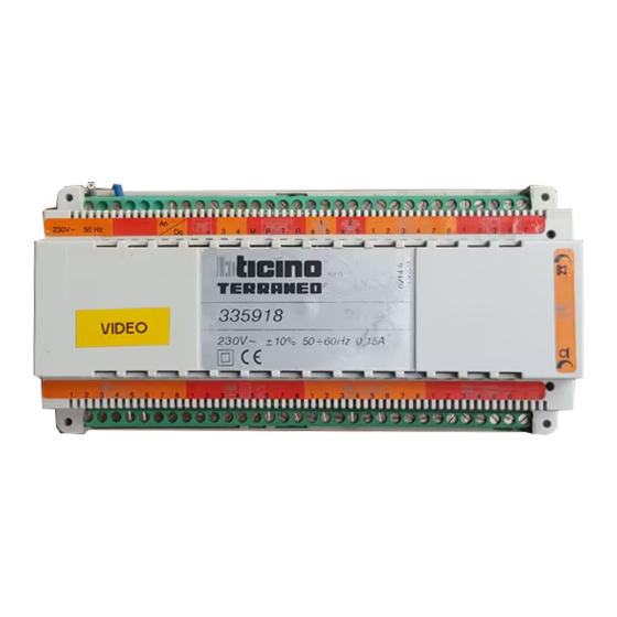
- Page 1 ® Instructions for use and installation ® item 335918...
- Page 2 Telephonic system...
-
Page 3: Table Of Contents
® INTRODUCTION 1.1 WARNINGS AND TIPS 1.2 CONTENTS OF THE PACKAGE 1.3 GENERAL VIEW 1.4 GENERAL DESCRIPTION BASIC FUNCTIONS OF THE VIDEO DOOR ENTRY UNIT 2.1 SWITCHING ON THE MONITOR 2.2 SWITCHING ON SEVERAL MONITORS AT THE SAME TIME 2.3 AUTO-SWITCHING ON 2.4 CYCLICAL AUTO-SWITCHING ON 2.5 DOOR LOCK ADVANCED FUNCTIONS OF THE VIDEO DOOR ENTRY UNIT... -
Page 4: Introduction
Telephonic system 1 INTRODUCTION 1.1 WARNINGS AND TIPS Before proceeding with the installation read this manual carefully, because the guarantee will be automatically cancelled as a result of negligence, incorrect operation, improper use or tampering with the circuit by unauthorised people. The video distributor must be installed on a DIN rail using the cables supplied for connection to the PABX (item 335818 or 335828). -
Page 5: Contents Of The Package
® INTRODUCTION 1.2 CONTENTS OF THE PACKAGE The video distributor package contains: • video distributor item 335918 • cable with 6 conductors for connection to the PABX exchange (terminals 3 4 M P T R) • 2 wires with 2 conductors for connection between terminals 1 and of the video Distributor and the corresponding terminals of the extensions of the PABX exchange (item 335818 or 335828) -
Page 6: General View
Telephonic system INTRODUCTION 1.3 GENERAL VIEW IS 2 IS 1 PABX 230V 50 Hz 335918 0,15 A 60 Hz 230V OS 1 OS 2 MAIN OS dedicated OS Mains power supply 230Vac 50Hz Selection of the type of system (analog without jumper digital with jumper) Input for the connection of an external power supply (item 336010) to switch the two video door entry telephones on at the same time Terminals for the connection to the PABX exchange (item 335818 or 335828) to be... -
Page 7: General Description
8....9....MAIN IS ® (230V~50Hz) 230V~50Hz cos g = 0.5 230V 50 Hz P ABX MAIN OS Bticino S.p.A. PABX cod.335818 1999 BXSP 031 ”Min. Comunicazioni-DGCA” 335918 335828 0022 06 0,15 A 230V ±10% 0,15A 50 ∏ 60HZ 230V... - Page 8 MAIN IS ® CAMERA EXCHANGE (230V~50Hz) 230V~50Hz cos g = 0.5 230V 50 Hz P ABX F AX Bticino S.p.A. P ABX cod.335818 1999 BXSP 031 ”Min. Comunicazioni-DGCA” 0022 06 335918 335925 335828 230V ±10% 0,15A 50∏ 60HZ 230V...
-
Page 9: Basic Functions Of The Video Door Entry Unit
® BASIC FUNCTIONS OF THE VIDEO DOOR ENTRY UNIT 2.1 SWITCHING ON THE MONITOR When there is a door entry call, the monitor of the main IS switches on and the other devices ring (if enabled for the door entry call). If the answer is from the other video door entry telephone, the speaker and video connection is automatically transferred. -
Page 10: Switching On Several Monitors At The Same Time
Telephonic system BASIC FUNCTIONS OF THE VIDEO DOOR ENTRY UNIT 2.2 SWITCHING ON SEVERAL MONITORS AT THE SAME TIME When there is a door entry call, the monitors of the two programmed IS switch on and the other telephones ring (if enabled for the door entry call). If the answer is from a video door entry telephone, both the other and all the telephones are excluded. -
Page 11: Auto-Switching On
® BASIC FUNCTIONS OF THE VIDEO DOOR ENTRY UNIT 2.3 AUTO-SWITCHING ON pushbutton allows the CCTV of an OS, as follows: • Rest: the auto-switching on occurs on the main OS • Call signal: the auto-switching on occurs on the OS from which the call came •... -
Page 12: Advanced Functions Of The Video Door Entry Unit
Telephonic system ADVANCED FUNCTIONS OF THE VIDEO DOOR ENTRY UNIT This function can address a video door entry unit command at rest and in conversation (door lock or auto-switching on) on the outdoor station required. 3.1 AUTO-SWITCHING ON In the advanced mode this function allows the direct auto-switching on of the OS required without having to pass through all the previous OS in the cyclical order. - Page 13 ® ADVANCED FUNCTIONS OF THE VIDEO DOOR ENTRY UNIT 3.1.2 Systems with riser and dedicated OS Advanced auto-switching on direct to one of the riser OS Auto-switching on on OS 1 of the riser Auto-switching on on OS 2 of the riser Auto-switching on on OS 3 of the riser Auto-switching on on OS 4 of the riser This command can manage up to 4 riser OS in both analog and digital systems.
-
Page 14: Door Lock
To activate the door lock relay of dedicated OS 2 type: All the functions described in chapters 2 and 3 are possible using TERRANEO-Bticino video door entry telephones and telephones. For operation with other telephones see the PABX Exchange manual. -
Page 15: Programming
® PROGRAMMING 4.1 ACCESS TO PROGRAMMING • Lift the receiver • Type: • Type the access code (e.g. basic - If the access code is correct you will hear a start-dialling tone - If the code is incorrect you will hear a time-out tone. Lift the receiver and repeat the procedure described above. -
Page 16: Setting Switching On Outdoor Stations
Telephonic system PROGRAMMING 4.3 SETTING SWITCHING ON OUTDOOR STATIONS This command configures which of the OS will switch on when there is a video door entry telephone call. Also, the “Association OS 1 – EXT3” field of the table allows the EXTension 3 association of the Exchange with OS 1 (1) of the Video distributor, so that the exchange fast line (EXT1) can be used to connect a Fax or Modem. - Page 17 ® PROGRAMMING • System with modem/fax connected on EXT1 To make a single-family system with a modem/fax installed on EXTension 1 of the exchange (401) use the diagram shown below. In this system the IS1 (main) will be associated with EXTension 3 (403). Connection diagram between EXT3 and Monitor1 (401) (403)
-
Page 18: Setting Outdoor Stations And Cameras
Telephonic system PROGRAMMING 4.4 SETTING OUTDOOR STATIONS AND CAMERAS This command configures the system outdoor stations and cameras. The table “Type of OS” field defines whether the OS is riser or dedicated OS0: - if configured as riser (1), the number of door entry OS (from 01 to 15) will be indicated in the next field;... -
Page 19: Main Outdoor Station (Riser Or Dedicated)
® PROGRAMMING 4.5 MAIN OUTDOOR STATION (Riser or Dedicated) For each division this command can define the main OS to which the door lock and auto- switching on at rest commands will be sent. It enables/disables the Auto-switching on and Door lock functions of the other OS. Division 1 Division 2 Main OS... -
Page 20: Door Lock On Riser Activation Time
Use the special TiPBX software, version 3.1 or later, which can be downloaded free from the Internet site: www.bticino.it in the technical software section. For the connection use cable item 335919 to be connected to the IOIOI seat of the PABX exchange and to a serial port (COM1 –... -
Page 21: Simplified Programming With Type Diagrams
® SIMPLIFIED PROGRAMMING WITH TYPE DIAGRAMS SYSTEM TYPE PROGRAMMING This command is intended to simplify programming. After the installer has performed the programming access procedure (Page 13) he can program the whole system by typing the code “82” followed by the identification number (from 01 to 16) of the diagram chosen from the 16 type configurations (see table). - Page 22 Telephonic system SIMPLIFIED PROGRAMMING WITH TYPE DIAGRAMS Diagram number Diagram Diagram Diagram Diagram The table gives the configurations of the system types (page 22 and later) System with Exchange item 335818 or 335828 Diagram No. Dedicated OS Riser OS with 1 or 2 calls Extra camera Divisions Macrocommand...
-
Page 23: Personalising The Program
® SIMPLIFIED PROGRAMMING WITH TYPE DIAGRAMS PERSONALISING THE PROGRAM The system type diagrams given in the table on Page 20 expect precise configurations (e.g. one riser outdoor station) which the installer can however personalise. After activating a type diagram, the configuration can be modified at any time by using the specific macrocommands described in the PROGRAMMING chapter. -
Page 24: System Type Diagrams
Telephonic system SYSTEM TYPE DIAGRAMS DIAGRAM 1 MACROCOMMAND *82*01# Telephone 230V a.c. 1....4....7....2....5....8....50-60Hz 3....6....9....(403) Exchange 335818 335828 3 4 M P T R Telephone lines PLT1 PLT1 Note: only item 335828 has the second telephone line (U2) Main Dedicated outdoor station 1... - Page 25 ® Main I.S. Telephone + Pivot Video 1 Blue - 1 yellow 2 Red + 2 green 3 Orange 3 blue tel. Line 4 White-Orange 4 white tel. Line 5 brown bell 6 red 7 Green 7 black VID - (401) 8 White-Green 8 grey...
- Page 26 Telephonic system SYSTEM TYPE DIAGRAMS DIAGRAM 2 MACROCOMMAND *82*02# Telephone 230V a.c. 1....4....7....2....5....8....50-60Hz 3....6....9....(403) Exchange 335818 335828 3 4 M P T R Telephone lines PLT1 PLT1 Note: only item 335828 has the second telephone line (U2) Main Dedicated outdoor station 1...
- Page 27 ® Main I.S. Telephone + Pivot Video 1 Blue - 1 yellow 2 Red + 2 green 3 Orange 3 blue tel. Line 4 White-Orange 4 white tel. Line 5 brown bell 6 red 7 Green 7 black VID - (401) 8 White-Green 8 grey...
- Page 28 Telephonic system SYSTEM TYPE DIAGRAMS DIAGRAM 3 MACROCOMMAND *82*03# Telephone 230V a.c. 1....4....7....2....5....8....50-60Hz 3....6....9....(403) Exchange 335818 335828 3 4 M P T R Telephone lines PLT1 PLT1 Note: only item 335828 has the second telephone line (U2) Analog-Digital system to the floor distribution...
- Page 29 ® Main I.S. Telephone + Pivot Video 1 Blue - 1 yellow 2 Red + 2 green 3 Orange 3 blue tel. Line 4 White-Orange 4 white tel. Line 5 brown bell 6 red 7 Green 7 black VID - (401) 8 White-Green 8 grey...
- Page 30 Telephonic system SYSTEM TYPE DIAGRAMS DIAGRAM 4 MACROCOMMAND *82*04# Telephone 230V a.c. 1....4....7....2....5....8....50-60Hz 3....6....9....(403) Exchange 335818 335828 3 4 M P T R Telephone lines PLT1 PLT1 Note: only item 335828 has the second telephone line (U2) Analog-Digital system to the floor distribution...
- Page 31 ® Main I.S. Telephone + Pivot Video 1 Blue - 1 yellow 2 Red + 2 green 3 Orange 3 blue tel. Line 4 White-Orange 4 white tel. Line 5 brown bell 6 red 7 Green 7 black VID - (401) 8 White-Green 8 grey...
- Page 32 Telephonic system SYSTEM TYPE DIAGRAMS DIAGRAM 5 MACROCOMMAND *82*05# Telephone 230V a.c. 1....4....7....2....5....8....50-60Hz 3....6....9....(403) Exchange 335818 335828 3 4 M P T R Telephone lines PLT1 PLT1 Note: only item 335828 has the second telephone line (U2) Analog-Digital system to the floor distribution...
- Page 33 ® Main I.S. Telephone + Pivot Video 1 Blue - 1 yellow 2 Red + 2 green 3 Orange 3 blue tel. Line 4 White-Orange 4 white tel. Line 5 brown bell 6 red 7 Green 7 black VID - (401) 8 White-Green 8 grey...
- Page 34 Telephonic system SYSTEM TYPE DIAGRAMS DIAGRAM 6 MACROCOMMAND *82*06# Telephone 230V a.c. 1....4....7....2....5....8....50-60Hz 3....6....9....(403) Exchange 335818 335828 3 4 M P T R Telephone lines PLT1 PLT1 Note: only item 335828 has the second telephone line (U2) Main Dedicated outdoor station 1...
- Page 35 ® Main I.S. Telephone + Pivot Video 1 Blue - 1 yellow 2 Red + 2 green 3 Orange 3 blue tel. Line 4 White-Orange 4 white tel. Line 5 brown bell 6 red 7 Green 7 black VID - (401) 8 White-Green 8 grey...
- Page 36 Telephonic system SYSTEM TYPE DIAGRAMS DIAGRAM 7 MACROCOMMAND *82*07# Telephone 230V a.c. 1....4....7....2....5....8....50-60Hz 3....6....9....(403) Exchange 335818 335828 3 4 M P T R Telephone lines PLT1 PLT1 Note: only item 335828 has the second telephone line (U2) Analog-Digital system to the floor distribution...
- Page 37 ® Main I.S. Telephone + Pivot Video 1 Blue - 1 yellow 2 Red + 2 green 3 Orange 3 blue tel. Line 4 White-Orange 4 white tel. Line 5 brown bell 6 red 7 Green 7 black VID - (401) 8 White-Green 8 grey...
- Page 38 Telephonic system SYSTEM TYPE DIAGRAMS DIAGRAM 8 MACROCOMMAND *82*08# Telephone 230V a.c. 1....4....7....2....5....8....50-60Hz 3....6....9....(403) Exchange 335818 335828 3 4 M P T R Telephone lines PLT1 PLT1 Note: only item 335828 has the second telephone line (U2) Analog-Digital system to the floor distribution...
- Page 39 ® Main I.S. Telephone + Pivot Video 1 Blue - 1 yellow 2 Red + 2 green 3 Orange 3 blue tel. Line 4 White-Orange 4 white tel. Line 5 brown bell 6 red 7 Green 7 black VID - (401) 8 White-Green 8 grey...
- Page 40 Telephonic system SYSTEM TYPE DIAGRAMS DIAGRAM 9 with 2 divisions MACROCOMMAND *82*09# Telephone 230V a.c. 1....4....7....2....5....8....50-60Hz 3....6....9....(403) Exchange 335818 335828 3 4 M P T R Telephone lines PLT1 PLT1 Note: only item 335828 has the second telephone line (U2) Main Dedicated outdoor station 1...
- Page 41 ® Main I.S. Telephone + Pivot Video 1 Blue - 1 yellow 2 Red + 2 green 3 Orange 3 blue tel. Line 4 White-Orange 4 white tel. Line 5 brown bell 6 red 7 Green 7 black VID - (401) 8 White-Green 8 grey...
- Page 42 Telephonic system SYSTEM TYPE DIAGRAMS DIAGRAM 10 with 2 divisions MACROCOMMAND *82*10# Telephone 230V a.c. 1....4....7....2....5....8....50-60Hz 3....6....9....(403) Exchange 335818 335828 3 4 M P T R Telephone lines PLT1 PLT1 Note: only item 335828 has the second telephone line (U2) Main Dedicated outdoor station 1...
- Page 43 ® Main I.S. Telephone + Pivot Video 1 Blue - 1 yellow 2 Red + 2 green 3 Orange 3 blue tel. Line 4 White-Orange 4 white tel. Line 5 brown bell 6 red 7 Green 7 black VID - (401) 8 White-Green 8 grey...
- Page 44 Telephonic system SYSTEM TYPE DIAGRAMS DIAGRAM 11 with 2 divisions MACROCOMMAND *82*11# Telephone 230V a.c. 1....4....7....2....5....8....50-60Hz 3....6....9....(403) Exchange 335818 335828 3 4 M P T R Telephone lines PLT1 PLT1 Note: only item 335828 has the second telephone line (U2) Analog-Digital system to the floor distribution...
- Page 45 ® Main I.S. Telephone + Pivot Video 1 Blue - 1 yellow 2 Red + 2 green 3 Orange 3 blue tel. Line 4 White-Orange 4 white tel. Line 5 brown bell 6 red 7 Green 7 black VID - (401) 8 White-Green 8 grey...
- Page 46 Telephonic system SYSTEM TYPE DIAGRAMS DIAGRAM 12 with 2 divisions MACROCOMMAND *82*12# Telephone 230V a.c. 1....4....7....2....5....8....50-60Hz 3....6....9....(403) Exchange 335818 335828 3 4 M P T R Telephone lines PLT1 PLT1 Note: only item 335828 has the second telephone line (U2) Analog-Digital system to the floor distribution...
- Page 47 ® Main I.S. Telephone + Pivot Video 1 Blue - 1 yellow 2 Red + 2 green 3 Orange 3 blue tel. Line 4 White-Orange 4 white tel. Line 5 brown bell 6 red 7 Green 7 black VID - (401) 8 White-Green 8 grey...
- Page 48 Telephonic system SYSTEM TYPE DIAGRAMS DIAGRAM 13 with 2 divisions MACROCOMMAND *82*13# Telephone 230V a.c. 1....4....7....2....5....8....50-60Hz 3....6....9....(403) Exchange 335818 335828 3 4 M P T R Telephone lines PLT1 PLT1 Note: only item 335828 has the second telephone line (U2) Analog-Digital system to the floor distribution...
- Page 49 ® Main I.S. Telephone + Pivot Video 1 Blue - 1 yellow 2 Red + 2 green 3 Orange 3 blue tel. Line 4 White-Orange 4 white tel. Line 5 brown bell 6 red 7 Green 7 black VID - (401) 8 White-Green 8 grey...
- Page 50 Telephonic system SYSTEM TYPE DIAGRAMS DIAGRAM 14 with 2 divisions MACROCOMMAND *82*14# Telephone 230V a.c. 1....4....7....2....5....8....50-60Hz 3....6....9....(403) Exchange 335818 335828 3 4 M P T R Telephone lines PLT1 PLT1 Note: only item 335828 has the second telephone line (U2) Main Dedicated outdoor station 1...
- Page 51 ® Main I.S. Telephone + Pivot Video 1 Blue - 1 yellow 2 Red + 2 green 3 Orange 3 blue tel. Line 4 White-Orange 4 white tel. Line 5 brown bell 6 red 7 Green 7 black VID - (401) 8 White-Green 8 grey...
- Page 52 Telephonic system SYSTEM TYPE DIAGRAMS DIAGRAM 15 with 2 divisions MACROCOMMAND *82*15# Telephone 230V a.c. 1....4....7....2....5....8....50-60Hz 3....6....9....(403) Exchange 335818 335828 3 4 M P T R Telephone lines PLT1 PLT1 Note: only item 335828 has the second telephone line (U2) Analog-Digital system to the floor distribution...
- Page 53 ® Main I.S. Telephone + Pivot Video 1 Blue - 1 yellow 2 Red + 2 green 3 Orange 3 blue tel. Line 4 White-Orange 4 white tel. Line 5 brown bell 6 red 7 Green 7 black VID - (401) 8 White-Green 8 grey...
- Page 54 Telephonic system SYSTEM TYPE DIAGRAMS DIAGRAM 16 with 2 divisions MACROCOMMAND *82*16# Telephone 230V a.c. 1....4....7....2....5....8....50-60Hz 3....6....9....(403) Exchange 335818 335828 3 4 M P T R Telephone lines PLT1 PLT1 Note: only item 335828 has the second telephone line (U2) Analog-Digital system to the floor distribution...
- Page 55 ® Main I.S. Telephone + Pivot Video 1 Blue - 1 yellow 2 Red + 2 green 3 Orange 3 blue tel. Line 4 White-Orange 4 white tel. Line 5 brown bell 6 red 7 Green 7 black VID - (401) 8 White-Green 8 grey...
-
Page 56: Installation
336900. This cable has been designed for the Terraneo digital system and is made up of 3 pairs of individually twisted conductors for the signals and 2 conductors for the low-voltage power supply of the devices. -
Page 57: Connections Between Distributor And Exchange
® INSTALLATION 7.3 CONNECTIONS BETWEEN DISTRIBUTOR AND EXCHANGE The Video Distributor must be installed on DIN rail. The connections to the PABX exchange are made using the cables supplied. Connect the 6-conductor cable to terminals 3 – 4 – M – P – T – R of the Video Distributor and the PABX exchange. -
Page 58: Connections To Expansions With Pabx
Telephonic system INSTALLATION 7.4 CONNECTIONS TO EXPANSIONS WITH PABX All the basic functions offered by the PABX exchanges can also be expanded with the relevant accessories (see telephone exchange items 335818 and 335828 manuals) in applications with the Video distributor. Diagram with relay expansion module for remote operation max 1 metre max 1 metre... -
Page 59: Installation Of The Video Door Entry Telephones
® INSTALLATION OF THE VIDEO DOOR ENTRY TELEPHONES 8.1 COMPOSITION OF THE VIDEO DOOR ENTRY TELEPHONES The video door entry telephone (telephone + video section) can be made up depending on the type of telephone (compact or standard) and the colour (white or grey). For a suitable combination consult the following tables. -
Page 60: Wall-Mounted Installation
Telephonic system INSTALLATION OF THE VIDEO DOOR ENTRY TELEPHONES 8.2 WALL-MOUNTED INSTALLATION • To install wall-mounted video door entry telephones, connect the unbraided wire (1) supplied with the Pivot telephone following the correspondence between the terminals of the Distributor (or Expander) and the conductor colours as indicated in the table. UNBRAIDED CABLE DISTRIB. -
Page 61: Appendix
® APPENDIX 9.1 TECHNICAL DATA Power supply 230 Vac –10% 50Hz Maximum absorption 120 mA max 50Hz Operating temperature from 0¡C to +40¡C Dimensions 10 DIN modules Weight 925 g... - Page 62 Telephonic system NOTE...
- Page 63 ®...
- Page 64 Telephonic system ® BTicino s.p.a. Via Messina, 38 20154 Milano - Italia www.bticino.com...
Need help?
Do you have a question about the Terraneo and is the answer not in the manual?
Questions and answers