Table of Contents
Advertisement
Advertisement
Table of Contents

Related Manuals for Tharo Systems H-435+

Summary of Contents for Tharo Systems H-435+
- Page 1 H-427+ and H-435+ Users Manual Date: 01-26-2015...
-
Page 2: Table Of Contents
CONTENTS Barcode Printer Box Contents Getting to Know Your Printer Printer Setup Loading Labels Loading Ribbon Connecting the Printer to the Host Computer your Computer EASYLABEL Start installation Windows Driver installation Printer Settings and Control Operation Panel LCD Interface Introduction LCD Interface Functions Label Calibration and Self-Test Error Alerts... - Page 3 FCC COMPLIANCE STATEMENT FOR AMERICAN USERS This equipment has been tested and found to comply with the limits for a CLASS A digital device, pursuant to Part 15 of the FCC Rules. These limits are designed to provide reasonable protection against harmful interference when the equipment is operated in a commercial environment.
-
Page 4: Safety Instructions
SAFETY INSTRUCTIONS During the print process the Printhead will become hot. Do NOT attempt to clean the Printhead until it has had time to cool. The Printhead is the most fragile part of your Printer. Do NOT use sharp or hard objects to clean the Printhead. -
Page 5: Barcode Printer
Barcode Printer Box Contents Please check that all of the following items are included with your printer. H-427+ / H-435+ Printer USB Cable Quick Guide Empty Ribbon Core Power Cord Including EASYLABEL Start software and user’s manual. -
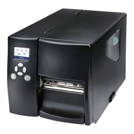
Page 6: Getting To Know Your Printer
Barcode Printer Getting to Know Your Printer 1. Operation Panel 2. Lower Cover Plate 3. Media Window 4. Top Cover 1. Fan-Fold Label Slot 2. Calibration Button 3. Parallel Port (optional) 4. Applicator Interface (optional) 5. USB Host 6. Ethernet Port 7. - Page 7 Barcode Printer 1. Ribbon Rewind Hub 2. Ribbon Supply Hub 3. Printer Mechanism 4. Platen 5. Tear-off Plate 6. Printhead Lever 7. Sensor Adjustment Knob 8. Label Guide 9. Label Tension Guide 10. Label Supply Hub 11. Label Roll Guide 12.
-
Page 8: Printer Setup
Printer Setup Loading Labels This printer supports the following printing methods: Thermal Transfer Printing (TTP) Requires a ribbon for transferring the printed image to the labels. Direct Thermal Printing (DTP) oes not require a ribbon. Verify which printing method you are using and modify the settings in the printer driver, printer menu, and/or software. - Page 9 Printer Setup 5. Slide the roll of label stock onto the Label Supply Hub all the way back to the Printer’s inner wall 6. Rotate the Label Roll Guide back down and push it against the label roll. Avoid pushing the Guide too far or you will damage the edge of the label stock.
- Page 10 Printer Setup 9. Position the edge of the label stock against the Printer’s center wall and then position the Label Guide against the outside edge of the label stock. 10. Rotate the Printhead Lever back to its original position. 11. Close the Top Cover to complete the label installation.
-
Page 11: Loading Ribbon
Printer Setup Loading Ribbon 1. Open the Printer’s top cover. 2. Pull the Printhead Lever out and rotate it upward to the right (counterclockwise) to open the Printhead. 3. Place the new ribbon roll onto the Ribbon Supply Hub and place an empty ribbon core onto the Ribbon Rewind Hub. -
Page 12: Connecting The Printer To The Host Computer Your Computer
Printer Setup Connecting the Printer to your Computer Ensure that the printer is turned off. Connect the power cord to the printer. Plug the power cord into an electrical outlet. Connect the USB cable to the printer and your computer. Turn the printer on. -
Page 13: Easylabel Start Installation
Printer Setup EASYLABEL Start Installation EASYLABEL Start is the free labeling package included with every Tharo printer. Insert the product CD into CD/DVD drive of your computer. Open the "install” folder on the CD. Right click on the setup.exe icon and choose “Run as Administrator” to start the installation. Select a language for the installation and click OK to continue. - Page 14 Printer Setup The next screen allows you to specify the directory to install EASYLABEL into. In most cases the default is fine. You may also specify if you want an EASYLABEL icon on your desktop. Click on “Next” to continue. The next step allows you to specify the installation type.
- Page 15 Printer Setup The Status screen will show the progress of the EASYLABEL Start installation. The installation is complete. Click “Finish” to close the InstallShield Wizard. You are ready to start using EASYLABEL. If you are a new EASYLABEL user we recommend that you view the EASYTutor tutorials.
-
Page 16: Windows Driver Installation
Printer Setup Printer Setup Printer Setup Windows Driver Installation Windows Drivers are NOT needed when printing to your Tharo Printer with EASYLABEL. If you want to print to your Tharo Printer from other Windows applications then a Windows driver is needed. Insert the product CD into CD/DVD drive of your computer. - Page 17 Printer Setup Printer Setup The printer can be installed on Windows releases other than Windows 8 or Windows 10 without any special steps. Insert the product CD into CD/DVD drive of your computer. Turn the printer on and connect it to your computer with a USB cable. The “Found New Hardware Wizard”...
-
Page 18: Printer Settings And Control
Printer Settings and Control Operation Panel Introduction LCD SCREEN DIRECTION BUTTONS FEED BUTTON POWER BUTTON POWER Button Press the POWER button to turn on the printer. Press and hold the POWER button for 3 seconds to turn the printer off. FEED Button Press the FEED button to advance the media. -
Page 19: Lcd Interface Introduction
Printer Settings and Control LCD Interface Introduction Getting Started Press the POWER button to turn on the printer. You will see the START UP SCREEN while the printer is booting up. Power on 1.007 - 140801 LCD Firmware Version Once the printer has booted, the LCD screen will display “Ready“. This indicates the printer is online and ready for use. - Page 20 Printer Settings and Control Navigating and making Changes On the MAIN MENU page, press the4 or 3 button to move the cursor. Highlight a selection and press the FEED button, you will then enter the SETTING PAGES for that selection. Select Label Settings Enter...
- Page 21 Printer Settings and Control On SETTING VALUE PAGES, press the 5 or 6 button to change the setting values. Select Press the FEED button to apply the value you just selected, and a red tick will appear next to the value. Apply **** The blue arrow indicates the current value.
- Page 22 Printer Settings and Control Exit from the Current Page and Return to Ready Status The navigation icon on top-left corner of the screen displays the icon for the last level screen. NAVIGATION ICON On SETTING VALUE PAGES, press the 3button to go back to the SETTING PAGE level screen. Back to the SETTING PAGE On SETTING PAGES, press the 5 button to go back to the MAIN MENU screen.
- Page 23 Printer Settings and Control To Exit the MAIN MENU PAGE, use the 4 or 3button to highlight the “EXIT” icon and then press the FEED button. Select EXIT Press the FEED Button The Printer returns to Ready status H-427+ V1.R91...
-
Page 24: Lcd Interface Functions
Printer Settings and Control Status of LCD Interface When printer is on standby (ready to print), the LCD will display “Ready” on screen. You can only print when you see the “Ready“ status. H-427+ V1.R91 The LCD screen will display error messages on the screen when they occur. See section 3.5 for the list of errors, causes and solutions. - Page 25 Printer Settings and Control LCD Interface Function Main Menu Page Printer Settings Printer Settings - Setting options for printing such as Printing speed, darkness, etc. Label Settings- Setting options for the label such as label rotation, Printing position, label offset, etc. Devices- Setting options for optional modules and communication ports.
- Page 26 Printer Settings and Control The “Wizard” menu provides quick access to the more commonly changed printer settings. Available Settings English Deutsch LCD Language Printer Settings Français Español 日本語 Italiano Pусский Türk 2-7 based on print resolution Speed Darkness 0-19 Label with Gaps Media Type Label with Marks Wizard...
- Page 27 Printer Settings and Control Apply Buzzer Cancel None Cutter Option Devices Label Dispenser Option Setting Applicator Apply Smart Backfeed Cancel 4800 bps 9600 bps 19200 bps Baud Rate 38400 bps 57600 bps 115200 bps Serial Port Settings None Parity Even 7 bits Data bits 8 bits...
-
Page 28: Label Calibration And Self-Test
Printer Settings and Control Label Calibration and Self Test Label Calibration The printer can automatically detect and store label height. That means the host computer does not need to transmit the label height to the printer. Self Test The Self Test function lets you check whether the printer is functioning normally. Follow these steps to run the Label Calibration and Self Test. - Page 29 Printer Settings and Control Label Calibration Button The Label Calibration button is used to perform a Label Calibration. This is useful to correct any Media Errors that may occur when changing the labels to another type, such as changing gap labels to black mark labels or continuous media. CALIBRATION BUTTON Press Press and hold the Calibration Button for 2 seconds to start the Label Calibration.
-
Page 30: Error Alerts
Printer Settings and Control Error Alerts In the event of a problem that prevents normal functioning of the printer, you will see an error message on LCD screen and hear some beep signals. Please refer to below table for the errors, causes and possible solutions. LCD SCREEN OPERATION PANEL DIRECTION KEY... - Page 31 Printer Settings and Control Type Beeps Description Solution Make sure that the label sensor is positioned correctly. If the No labels are sensor still does not detected. detect the paper, run the auto- detection function again. Replace the label Label stock is H-427+ V1.R91 used up.
-
Page 32: Usb Host And Standalone
Printer Settings and Control USB Host and Standalone Mode USB Host Uses The USB Host port supports the use of a USB memory stick, keyboard or scanner. A USB memory stick can be used to extend the user accessible storage memory up to 32GB The printer’s Firmware also can be updated using a USB memory stick. - Page 33 Printer Settings and Control USB Keyboard Plug a USB keyboard into the printer and the “Enter Standalone?” prompt will appear on the LCD. Press the “Y” key on keyboard to enter Standalone Mode. You can also press “F1” on the keyboard to enter Standalone Mode from the “Ready”...
-
Page 34: Netsetting For Ethernet
NetSetting for Ethernet Installing the NetSetting software The NetSetting software is used to manage the network configuration of the Ethernet port. NetSetting is available on the CD that ships with the printer or it can be downloaded from our website (www.tharo.com). To install NetSetting: Insert the Printer CD in your computer’s CD/DVD drive. -
Page 35: Netsetting Interface
NetSetting for Ethernet NetSetting Interface Doubleclick on the NetSetting icon to start the program. You will see the start page below. The start page will display the basic information of any connected printer and your PC. ZX1200 Click on the magnifying glass icon to search your network for Tharo Ethernet printers. Any printers that are detected are listed on the start page. - Page 36 NetSetting for Ethernet IP Setting On the IP Setting tab you can change the Printer Name, Port Number, Default Gateway and Password. You can also set the printer’s IP address either by DHCP or by Static IP. Click the “Set” button to apply the settings and the “Refresh” button to re-query the printer and refresh the values. **** To fully benefit from the NetSetting software, you should be familiar with basic networking principles.
- Page 37 NetSetting for Ethernet Alert Mail Setting The Printer can send the alert messages to a designated mail account when errors occur. The alert messages are sent by SMTP (Simple Mail Transfer Protocol) or SNMP (Simple Network Management Protocol). You can set or change the configurations of SMTP and SNMP on the “Alert Mail Setting” tab. Click the “Set”...
- Page 38 NetSetting for Ethernet Alert Message Setting Here you can specify which errors should trigger sending an email. The alert messages can be sent by SMTP, SNMP or both. Click the “Set” button to apply the settings and the “Refresh” button to re-query the printer and refresh the values.
- Page 39 NetSetting for Ethernet Printer Configuration This tab allows you to change the configuration of the connected printer. Many of the printer settings can be modified on this setting page. ZX1200i T-4210 English Click the “Set” button to apply the settings and the “Refresh” button to re-query the printer and refresh the values.
- Page 40 NetSetting for Ethernet Terminal The “Terminal” tab provides a communication interface for operator to control the printer. Enter printer commands into the "Input Command" window and press the “Send Command” button, the commands will be sent to the printer. For the commands that return a response message, the message will be displayed in "Output Message" window. Click on the “Clear Data”...
- Page 41 NetSetting for Ethernet Firmware Upgrade The current printer firmware version is shown on the “Firmware Upgrade” tab. You may also upgrade the printer firmware from this screen. Simply click the “browse” button and specify the firmware file location. Then click the “Start Download Firmware” button. The printer firmware will be updated remotely. BOOT : 1.000a1 F/W : ZX1200i 1.000a In addition to the firmware update, you can click the “Recover To Factory Settings”...
-
Page 42: Accessories
Accessories Internal Rewinder Components 1. Rewind Module 2. U Shaped Clip 3. Screws (4) 4. Rewind Guide Suggested Label Liner thickness: 0.06mm +/- 10% weight 65g/m2 +/- 6% 1. Open the Top Cover of the Printer. 2. Remove the Rewind Module Cover Plate. - Page 43 Accessories 3. Remove the U Shaped Metal Clip from the rewind shaft (1). 4. Install the Internal Rewind module using the 4 supplied screws (2). 5. After installing the Internal Rewind Module, plug the cable connector into the rewind control socket. 6.
-
Page 44: Installing The Rewinder Guide
Accessories Installing the Rewinder Guide 1. Face the front of the Printer and remove the Lower Cover Plate Screw. 2. Remove the Lower Cover Plate. 3. Mount the Label Rewind Guide onto the Printhead Mechanism and secure with the screws provided. 4. -
Page 45: Label Dispenser (Strip-And-Peel Setup)
Accessories Label Dispenser (Strip-and-Peel Setup) 1. Face the front of the Printer and remove the Lower Cover Plate Screw. 2. Remove the Lower Cover Plate. 3. Pull the Printhead Lever out and rotate it upward to the right (counterclockwise) to open the Printhead. (2) 4. - Page 46 Accessories 7. Wrap the liner around the Rewind Module (1), and use the U Shaped Metal Clip (2) to secure the liner. 8. Rotate the Printhead Lever back to its original position. 9. Replace the Lower Cover Plate and tighten the Lower Cover Plate Screw.
-
Page 47: Cutter Installation
Accessories Cutter Installation Components 1. Cutter Cover 2. Cutter Module 3. Cable Clips 4. Screws Do not use to cut adhesive labels! Glue residue will be left on the cutter blade and impair its function. The cutter has a blade life of 500,000 cuts when using paper weighing 160 g/m²... - Page 48 Accessories 4. Secure the Cutter to the Printer with two screws. 5. Plug the Cutter cable into the cutter connector on the center wall. 6. Insert the cable into the locks. Peel the backing off the locks and then secure them to the bottom plate 7.
-
Page 49: Installing The Parallel Adapter
Accessories Installing the Parallel Adapter Components 1. Parallel Cable 2. Parallel Adapter 3. Connection Cable 4. Screws 1. Place the Printer on a flat surface and open the Top Cover. 2. Remove the two screws marked in the illustration on the right. Close the Top Cover. - Page 50 Accessories 4. Install the Parallel Adapter in its place and secure it with two screws. 5. Attach the 30-pin Connection Cable to the motherboard. 6. Replace the left-hand side of the printer housing and secure it with two screws. 7. The installation of the Parallel Adapter is complete.
-
Page 51: Maintenance And Adjustment
Maintenance and Adjustment Removing / Installing the print head module 1. Open the Printer’s top cover. 2. Pull the Printhead Lever out and rotate it upward to the right (counterclockwise) to open the Printhead. 3. Gently pull the Printhead assembly towards you. -
Page 52: Adjusting The Print Line
Maintenance and Adjustment Adjusting the print line When printing on stiff or thick paper, the Print Line needs to be moved forward (paper feed direction) in order to achieve better print quality. 1. Open the Printer’s top cover. 2. Pull the Printhead Lever out and rotate it upward to the right (counterclockwise) to open the Printhead. -
Page 53: Adjusting Ribbon Tension
Maintenance and Adjustment Adjusting the ribbon tension Due to differences in ribbon material, ribbon wrinkles may occur during printing. When this happens increase the ribbon tension by: 1. Pushing the end of the shaft in. 2. Then turn the ribbon shaft clockwise to increase the tension. If narrower ribbons are being used (especially ribbon widths of less than 2”), the Printer might have a problem feeding labels. -
Page 54: Cleaning The Thermal Print Head
Maintenance and Adjustment Cleaning the thermal print head Printing labels will cause dirt such as paper dust, particles of ink and label adhesive to accumulate on the thermal print head. This can cause poor print quality and incomplete print outs. When this happens, the print head must be cleaned: 1. -
Page 55: Printhead Balance And Tension Adjustment
Maintenance and Adjustment Printhead balance and tension adjustment If one side of the printed labels is not being printed clearly, or if ribbon wrinkles occur, then adjust the Thermal Printhead Spring Box position/tension to cure the problem. 1. Pull the Printhead Lever out and rotate it upward to the right (counterclockwise) to open the Printhead. -
Page 56: Ribbon Shield Adjustment
Maintenance and Adjustment Ribbon shield adjustment If ribbon wrinkle occurs during printing, adjust the ribbon shield. Example: If ribbon wrinkle occurs as shown in figure (a), please turn the ribbon shield screw A clockwise, and if ribbon wrinkle occurs as shown in figure (b), please turn the ribbon shield screw B clockwise. For best results, only adjust the screw by one half turn for each test print. -
Page 57: Cleaning The Cutter
Maintenance and Adjustment Cleaning the Cutter 1. If the Cutter jams or malfunctions turn the Printer Off. 2. Remove the Cutter assembly from the Printer. 3. Remove any jammed paper. 4. Wet a cotton swab in Isopropyl Alcohol and use it to remove any build-ups of adhesive. -
Page 58: Troubleshooting
Maintenance and Adjustment Troubleshooting Problem Solution Check the power supply. ♦ The printer is switched on but the LED does not light up. Check for software setting or program command errors. ♦ Look for the error in Section 3.3 Error Alerts The LED lights up red and printing has ♦... -
Page 59: Appendix
APPENDIX PRODUCT SPECIFICATIONS H-427+ H-435+ EASYLABEL Start Windows and CUPS (Linux and Mac) Notice Specifications are subject to change without notice. All company and/or product names are trademarks and/or registered trademarks of their respective owners. -
Page 60: Interface Specifications
APPENDIX INTERFACE Parallel Port (Optional) Handshaking : DSTB is sent to the printer, BUSY to the host computer Interface : Parallel cable compatible with IBM computers cable Pinout : See below Pin No. Function Transmitter /Strobe Computer / printer Data 0-7 Computer /Acknowledge Printer... - Page 61 APPENDIX INTERFACE Computer Connector: Type A Pin NO. Function VBUS Connector Type: Type B Pin NO. Function VBUS PIN NO. FUNCTION PIN NO. Printer Print Printed Printing FUNCTION +5 V Error +24 V Ground Signal Signal Signal Signal...
Need help?
Do you have a question about the H-435+ and is the answer not in the manual?
Questions and answers