Table of Contents
Advertisement
Quick Links
Advertisement
Table of Contents

Related Manuals for HMS Anybus X-Gateway Series


Summary of Contents for HMS Anybus X-Gateway Series
-
Page 1: User Manual
User Manual Anybus® X-gateway Doc: HMSI-27-262 Rev: 2.10 Connecting Devices HMS Industrial Networks Mailing address: Box 4126, 300 04 Halmstad, Sweden E-mail: info@hms-networks.com Visiting address: Stationsgatan 37, Halmstad, Sweden Web: www.anybus.com... -
Page 2: Important User Information
Liability Every care has been taken in the preparation of this manual. Please inform HMS Industrial Networks AB of any inaccuracies or omissions. The data and illustrations found in this document are not binding. We, HMS Industrial Networks AB, reserve the right to modify our products in line with our policy of continuous product development. -
Page 3: Table Of Contents
Table of Contents Table of Contents Preface About This Document Important User Information........................4 Document History ........................... 5 Revision List............................ 5 Conventions & Terminology ........................5 Support............................... 5 Chapter 1 About the Anybus X-gateway Introduction .............................. 6 Functional Overview..........................6 External View............................ - Page 4 Chapter 2 Basic Operation Data Exchange............................9 Status & Diagnostics ..........................10 Status Word ..........................10 Live List (Master Configurations Only) ..................11 Network Specific Status ......................... 11 Controlling the Gateway from the Network..................12 Control Word ..........................12 Network Specific Controls ......................12 Data Mapping............................
-
Page 5: Document History
Preface P. About This Document This document provides an understanding of the functionality shared by the various versions of the Anybus X-gateway. It does not, however, cover any network-specific features. These are instead covered in separate documents known as Interface Addendums. The reader is expected to be familiar with communication systems in general, and industrial networking systems in particular. -
Page 6: About The Anybus X-Gateway
Chapter 1 1. About the Anybus X-gateway 1.1 Introduction The Anybus X-gateway is a series of network gateways, used to provide a seamless connection between two networks of different types. The gateway is based on patented Anybus technology; a proven industrial communi- Network 1 cation solution used by leading manufac- turers of industrial automation products... -
Page 7: External View
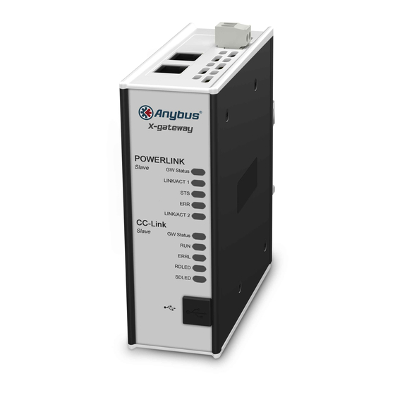
About the Anybus X-gateway 8 1.3 External View The flexible design of the X-gateway platform allows each network interface to be mounted at the top or bottom of the unit. Note that this will affect the orientation of the on-board switches and network connectors. -
Page 8: Installation
About the Anybus X-gateway 9 1.4 Installation 1.4.1 DIN-rail Installation The gateway is DIN-rail mountable. To ensure proper EMC behaviour, the DIN-rail must be connected to protective earth (PE). Snap On To fasten the gateway to the DIN-rail, align it with the DIN-rail connector, according to the figure shown here. -
Page 9: Data Exchange
Chapter 2 2. Basic Operation 2.1 Data Exchange Each of the two network interfaces exchange data on it’s network through two buffers. The gateway forwards the data between these buffers as shown below. Note that this process is separated from the network data exchange;... -
Page 10: Status & Diagnostics
Basic Operation 11 2.2 Status & Diagnostics 2.2.1 Status Word Optionally, the gateway provides runtime status and diagnostics through the Status Word. This func- tionality is disabled by default, but can be enabled separately for each network via the Gateway Config Interface. -
Page 11: Live List (Master Configurations Only)
Basic Operation 12 2.2.2 Live List (Master Configurations Only) Optionally, the gateway provides a list of the active status of the slaves associated with the on board mas- ter. The list is assembled by the master interface and forwarded to the other network each gateway cycle. This functionality is disabled by default, but can be enabled via the Gateway Config Interface. -
Page 12: Controlling The Gateway From The Network
Basic Operation 13 2.3 Controlling the Gateway from the Network 2.3.1 Control Word It is possible to control certain aspects of the gateway from the network by setting the corresponding bits in the Control Word. This functionality is disabled by default, but can be enabled separately for each network interface through the Gateway Config Interface. -
Page 13: Data Mapping
Basic Operation 14 2.4 Data Mapping If enabled, the Control- and Status Words, and the Live List (when available), affects how data is mapped to the on-board network interfaces. Note: The actual representation of the data on the network is highly network specific and is described in detail in the interface addendums for your product. -
Page 14: Error Handling
Basic Operation 15 2.5 Error Handling When a network goes off line, it is often desirable to have certain control over what happens on the other network. The gateway can either freeze (keep the current value) or clear (set to zero) the data from the network that has gone off line. -
Page 15: Anybus Configuration Manager
Chapter 3 3. Anybus Configuration Manager 3.1 General Information In general, the X-gateway requires very little effort to get it up and running. However, since all networks are different, certain settings may need adjustment to suit a particular application. This can be achieved by using the Anybus Configuration Manager (ACM), which accesses the gateway settings via the USB connector. -
Page 16: Open Communication To The X-Gateway
Anybus Configuration Manager 17 3.2 Open Communication to the X-gateway 1. Connect a USB cable between the USB port on the X-Gateway and a USB port on the PC. 2. Start Anybus Configuration Manager. The window will look much like the example here. 3. -
Page 17: Download And Change The Configuration
Anybus Configuration Manager 18 3.3 Download and Change the Configuration Now that Anybus Configuration Manager has an active connection to the X-gateway, the interface con- figurations from the unit can be uploaded, viewed and modified. 1. Click Upload configuration from X-gateway. 2. -
Page 18: Connectors And Cables
Chapter 4 4. Connectors and Cables 4.1 Power Supply Signal Ground ±20%, Class 2 +24V DC 4.2 Gateway Config Interface (USB) The configuration interface for the Anybus X-Gateway is provided via a USB-B socket on the front sur- face. Note that all other network-specific connectors are detailed in the documentation for each network. Anybus X-gateway User Manaul Doc: HMSI-27-262, Rev: 2.10... -
Page 19: Appendix A Mechanical Drawings
Appendix A A. Mechanical Drawings Anybus X-gateway User Manaul Doc: HMSI-27-262, Rev: 2.10... -
Page 20: Power
Appendix B B. Technical Specifications Power The gateway requires a regulated 24V±20% DC Class 2 power source. Maximum power consumption is 400mA at 24VDC. Typical consumption is 200mA at 24VDC. Protective Earth and Shielding The product must be connected to protective earth (PE) via the DIN-rail connector in order to achieve proper EMC behaviour.
Need help?
Do you have a question about the Anybus X-Gateway Series and is the answer not in the manual?
Questions and answers