
Related Manuals for ANTAIRA LNX-800N


Summary of Contents for ANTAIRA LNX-800N
- Page 1 8-Port 10/100TX SNMP Managed Industrial Ethernet Switch with Redundant Ring User Manual...
-
Page 2: Fcc Warning
FCC Warning This Equipment has been tested and found to comply with the limits for a Class-A digital device, pursuant to Part 15 of the FCC rules. These limits are designed to provide reasonable protection against harmful interference in a residential installation. -
Page 3: Table Of Contents
Content Introduction ..............1 Features ..............1 Package Contents ............ 2 Hardware Description ..........3 Physical Dimension ..........3 Front Panel ............... 3 Reset Button ..............4 Bottom View ............. 4 DIP-switch ..............4 LED Indicators ............6 Ports ................. 7 Cabling .............. - Page 4 Wall Mount Plate Mounting ........14 Hardware Installation ..........15 Network Application ..........16 Redundant Ring Application ........16 Coupling Ring Application ........17 Dual Homing Application ........18 Web-Based Management ........19 About Web-Based Management ......19 Preparing for Web Management ......19 System Login ............
- Page 5 Power Alarm Configuration ..........35 IP Configuration ............35 SNTP Configuration ..........36 IP Security .............. 39 RSTP Configuration ..........40 Redundant ring ............44 QoS Configuration ..........46 IGMP ..............48 SNMP Configuration ..........49 Security Manager ........... 51 Configuration Backup ..........
-
Page 6: Introduction
Introduction The 8-port 10/100TX SNMP Managed Industrial Ethernet Switch with Redundant Ring is a cost- effective solution and meets the high reliability requirements demanded by industrial applications. The 8-port 10/100TX SNMP Managed Industrial Ethernet Switch with Redundant Ring can be easily managed through the Web GUI. -
Page 7: Package Contents
Simple Network Time protocol supported Management IP security TFTP firmware update and system configuration restore and backup 1Mbits Embedded memory 2K MAC address table NMP, Web management, RMON supported Package Contents Please refer to the package content list below to verify them against the checklist. -
Page 8: Hardware Description
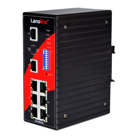
Hardware Description In this paragraph, we will introduce the Industrial switch’s hardware spec, port, cabling information, and wiring installation. Physical Dimension 8-port 10/100TX SNMP Managed Industrial Ethernet Switch with Redundant Ring dimension (W x H x D) is 54mm x 135mm x 105mm Front Panel The Front Panel of the 8-port 10/100TX SNMP Managed Industrial Ethernet Switch with Redundant Ring is showed as following figure. -
Page 9: Reset Button
Reset Button The reset button provides user a quick and easy way to restart and set the configuration back to default value. Restart: press the button for 2 seconds and release. Set to factory default value: press the button for 5 seconds and release. The switch will set all configurations back to default setting. - Page 10 DIP Switch No Status Description Disable port 1 Alarm Enable port 1 Alarm. If the port’s link fails, the fault LED will light up. Disable port2 Alarm Enable port 2 Alarm. If the port’s link fails, the fault LED will light up. Disable port3 Alarm Enable por3 t Alarm.
-
Page 11: Led Indicators
Disable port8 Alarm Enable port8 Alarm. If the port’s link fails, the fault LED will light up. Disable the ring master function. Enable the switch as the ring master in the redundant ring group. [NOTE] When port alarm function is enabled, the fault LED will on and Alarm relay will activity when port failure occurs. -
Page 12: Ports
No Power failure or UTP port failure or Fiber port failure occurs The industrial switch is the master of Green redundant ring group. R. M. (Ring Master) The industrial switch is not a ring master in redundant ring group. Green The port is linking. - Page 13 RJ-45 Pin Assignments Pin Number Assignment [NOTE] “+” and “-” signs represent the polarity of the wires that make up each wire pair. All ports on this industrial switch support automatic MDI/MDI-X operation, you can use straight-through cables (See Figure below) for all network connections to PCs or servers, or to other switches or hubs.
-
Page 14: Cabling
Cross Over Cable Schematic Cabling Use four twisted-pair, Category 5 cabling for RJ-45 port connection. The cable between the converter and the link partner (switch, hub, workstation, etc.) must be less than 100 meters (328 ft.) long. -
Page 15: Wiring The Power Inputs
Wiring the Power Inputs Please follow below steps to insert the power wire. V- V+ V- V+ 1. Insert the positive and negative wires into the V+ and V- connector on the terminal block connector. 2. To tighten the wire-clamp screws for preventing the DC wires to loose. -
Page 16: Wiring The Fault Alarm Contact
Wiring the Fault Alarm Contact The fault alarm contact is in the middle of terminal block connector as below figure shows. By inserting the wires and set the DIP switch at “ON” status, it will detect when power is failure or port link failure and form a closed circuit. And, the following figure shows an application example for the fault alarm contact. -
Page 17: Mounting Installation
Mounting Installation DIN-Rail Mounting The DIN-Rail is screwed on the industrial switch when out of factory. If the DIN-Rail is not screwed on the industrial switch, please see the following figure to screw the DIN-Rail on the switch. Follow the below steps to hang the industrial switch. - Page 18 First, insert the top of DIN-Rail into the track. Then, lightly push the DIN-Rail into the track. Check the DIN-Rail is tightly on the track. To remove the industrial switch from the track, reverse steps above.
-
Page 19: Wall Mount Plate Mounting
Wall Mount Plate Mounting Follow the below steps to mount the industrial switch with wall mount plate. 1. Remove the DIN-Rail from the industrial switch; loose the screws to remove the DIN-Rail. 2. Place the wall mount plate on the rear panel of the industrial switch. 3. -
Page 20: Hardware Installation
Hardware Installation In this paragraph, it will describe how to install the 8-port 10/100TX SNMP Managed Industrial Ethernet Switch with Redundant Ring and the installation points for attention. 1. Unpack the Industrial switch. 2. Check the DIN-Rail is screwed on the Industrial switch. If the DIN-Rail is not screwed on the Industrial switch. -
Page 21: Network Application
Network Application This chapter provides some sample applications to help user to have more actual idea of industrial switch function application. A sample application of the industrial switch as below: Redundant Ring Application The industrial switch supports the redundant ring protocol that can help your network system to recovery from network connection failure within 300ms or less, and make your network system more reliable. -
Page 22: Coupling Ring Application
Coupling Ring Application In the network, it may have more than one redundant ring group. By using the coupling ring function can connect each redundant ring for the redundant backup. It can ensure the transmissions between two ring groups will no failure. A sample of coupling ring application figure as below:... -
Page 23: Dual Homing Application
Dual Homing Application Dual Homing function is to prevent the connection lose between redundant ring group and upper level/core switch. The Dual Homing function only work when the redundant ring function is active. The maximum Dual Homing port is one in a redundant ring group. -
Page 24: Web-Based Management
Web-Based Management This section introduces the configuration and functions of the Web-Based management. The following configuration steps are based on the firmware version 1.06. About Web-Based Management On CPU board of the switch there is an embedded HTML web site residing in flash memory, which offers advanced management features and allow users to manage the switch from anywhere on the network through a standard browser such as Microsoft Internet Explorer. -
Page 25: System Login
Default Gateway: 192.168.1.254 User Name: admin Password: admin System Login Launch the Internet Explorer on the PC. Key in “http:// “+” the IP address of the switch”, and then Press “Enter”. The login screen will appear right after. Key in the user name and password. -
Page 26: Port Status
Port status Display every port status which depended on user’s setting and the negotiation result. Port: the port number Type: the speed mode, ex: 100TX = 100Mbps Link: “Down” means “No Link”. “UP” is for “Link” State: Display port statuses “disable”... -
Page 27: Port Statistics
Port information interface Port Statistics Display the current port statistic information. Click button to clean all Clear counts. Port Statistics Interface... -
Page 28: Port Control
Port Control Modifying the port status Select the port by scroll the Port column State: disable or enable control of his port Negotiation: set auto negotiation mode is Auto, Nway (specify the speed/duplex on this port and enable auto-negotiation), or Force Speed: Set the speed of the port Duplex: Set the port with full-duplex or half-duplex mode Flow control: Set flow control function is Symmetric or Asymmetric in... -
Page 29: Port Mirroring
bytes. System Location: Assign the switch physical location. The maximum length is 64 bytes. System Description: Display the description of switch. Read only cannot be modified. Firmware Version: Display the switch’s firmware version. Kernel Version: Display the kernel software version. ... -
Page 30: Vlan Configuration
Analysis Port: the mirror port will receive all monitored port traffic. The mirror port can connect with the LAN analyzer or Netxray. Monitor Port: the ports which user wants to monitor. All monitor port traffic will be copied to mirror port. Maximum 7 monitor ports can be selected in one switch. - Page 31 network devices to another Layer 2 switch. However, all the network devices are still plugged into the same switch physically. The industrial switch supports port-based and 802.1Q (tagged-based) VLAN. In the default configuration, VLAN operation mode default is “disable”. VLAN Configuration interface Port-based VLAN Packets can go among only members of the same VLAN group.
- Page 32 VLAN – PortBase interface Click to add a new VLAN group. The maximum VLAN group is up to 64 VLAN groups Enter the VLAN name, group ID and group the members of VLAN group Click Apply...
- Page 33 VLAN—PortBase Add interface The VLAN group list will display right after. Click to view other VLAN groups. Next Page button to delete unwanted VLAN. Delete button to modify existing VLAN group. Edit [NOTE] Remember to execute the “Save Configuration” action, otherwise the new configuration will lose when the switch power off.
- Page 34 All ports on the switch belong to default VLAN, VID is 1. The default VLAN can’t be deleting. The maximum VLAN group is up to 64 VLAN groups. 802.1q VLAN interface Basic Click button Management VLAN ID: it is used for Remote Management Security. In fact, it can remote management through SNMP, and Web browse the switch, only when the port of VLAN group ID is equal to the Management VLAN ID.
- Page 35 Management VLAN ID, it still has the right to remote management the switch. Group Name: Assign a name for the new VLAN VLAN ID: Fill in a VLAN ID (2~ 4094). The default is 1 Select ports from the ports list, and then, click to group the port as a VLAN group 802.1q VLAN –Add interface...
- Page 36 Set the outgoing frames are VLAN-Tagged frames or untagged, and then click Apply Tag: outgoing frames with VLAN-Tagged Untag: outgoing frames without VLAN-Tagged Port VID: Configure port VID settings Port VLAN ID: Enter the port VLAN ID Click Apply To reset to default value, click...
-
Page 37: Alert
802.1q VLAN – Port VLAN ID interface [NOTE] Remember to execute the “Save Configuration” action, otherwise the new configuration will lose when the switch power off. Alert There are three kinds of alert – e-mail, event, and power alarm. You can configure each alert function, as you needed. -
Page 38: Event Configuration
SMTP Server IP Address: Set up the mail server IP address Authentication: Mark the check box to enable and configure the email account and password for authentication Mail Account: Set up the email account to receive the alert. Ex: johnadmin@123.com. - Page 39 System event selection: 4 selections – Device cold start, Power status, SNMP Authentication Failure, and Redundant ring topology changes. Mark the checkbox to select the event. When selected events occur, the system will sent out the alerting. Device cold start: when the device executes cold start action, the system will send out the alert to the dedicate SMTP server.
-
Page 40: Power Alarm Configuration
Event Configuration interface Power Alarm Configuration Power alarm function enables the Relay alarm action. Without enabling power alarm function, the Relay alarm action will not work even the Relay alarm is set. Mark the check box and click button. Apply Power Alarm interface IP Configuration Configure the IP Settings and DHCP client function, and then click... -
Page 41: Sntp Configuration
apply the new IP settings. DHCP Client: Enable or Disable the DHCP client function. When DHCP client function is enabling, the industrial switch will be assigned the IP address from the network DHCP server. The default IP address will be replace by the DHCP server assigned IP address. - Page 42 SNTP Client: enable or disable SNTP function to get the time from the SNTP server Daylight Saving Time: enable or disable daylight saving time function. When daylight saving time is enabling, user need to configure the daylight saving time period UTC Timezone: Set the switch location time zone.
- Page 43 CET - Central European FWT - French Winter MET - Middle European +1 hour 1 pm MEWT - Middle European Winter SWT - Swedish Winter EET - Eastern European, +2 hours 2 pm USSR Zone 1 BT - Baghdad, USSR +3 hours 3 pm Zone 2...
-
Page 44: Ip Security
Daylight Saving Period: Configure the daylight saving time period Daylight Saving Offset (mins): Configure the offset value Click Apply [NOTE] Remember to execute the “Save Configuration” action, otherwise the new configuration will lose when the switch power off. SNTP Configuration IP Security IP security function allows user to assign 10 specific IP addresses which have permission to access the switch through the web browser for the securing... -
Page 45: Rstp Configuration
[NOTE] Remember to execute the “Save Configuration” action, otherwise the new configuration will lose when the switch power off. IP Security Interface RSTP Configuration The Rapid Spanning Tree Protocol (RSTP) is an evolution of the Spanning Tree Protocol and provides for faster spanning tree convergence after a topology change. - Page 46 parameters Priority (0-61440): a value used to identify the root bridge. The bridge with the lowest value has the highest priority and is selected as the root. If the values change, user has to reboot the switch. The value must be multiple of 4096 according to the protocol standard rule.
-
Page 47: Per Port Configuration
RSTP– System Configuration Interface Per Port Configuration Configuring the path cost and priority of every port 1. Select the port in Port column 2. Path Cost: The cost of the path to the other bridge from this transmitting bridge at the specified port. Enter a number 1 through 200000000. 3. - Page 48 P2P disabling. 5. Admin Edge: The port directly connected to end stations cannot create bridging loop in the network. To configure the port as an edge port, set the port to “True” status. 6. Admin Non Stp: The port includes the STP mathematic calculation. True is not including STP mathematic calculation.
-
Page 49: Redundant Ring
Redundant Ring Redundant Ring provides a faster redundant recovery than Spanning Tree topology. The action is similar with STP or RSTP, but the algorithms not the same. In the redundant ring topology, every switch should enable redundant ring function and assign two member ports in the ring. Only one switch in the redundant ring group would be set as a backup switch that one of two member ports would be blocking, called backup port, and another port is called working port. - Page 50 level/core switch. Enable Redundant ring: To enable the redundant ring function. Marking the check box to enable the redundant ring function. & 2 Working Ports: Assign two ports as the member ports. One port will be working port and one port will be the backup port. The system will automatically decide which port is working port and which port is backup port.
-
Page 51: Qos Configuration
time. 2. Remember to execute the “Save Configuration” action, otherwise the new configuration will lose when the switch power off. QoS Configuration Configure Qos setting of the every port. Oos Policy: Select the Qos policy rule Using the 8,4,2,1 weight fair queue scheme: the switch will follow 8:4:2:1 rate to process priority queue from Hi to lowest queue. - Page 52 When the packet received by port 1, the system will check the TOS value of the received IP packet. If the TOS value of received IP packet is 25(priority = high), and then the packet priority will have highest priority. [NOTE] QoS and Rate control cannot be existed at the same time.
-
Page 53: Igmp
IGMP The Internet Group Management Protocol (IGMP) is an internal protocol of the Internet Protocol (IP) suite. IP manages multicast traffic by using switches, routers, and hosts that support IGMP. Enabling IGMP allows the ports to detect IGMP queries and report packets and manage IP multicast traffic through the switch. -
Page 54: Snmp Configuration
IGMP Snooping interface SNMP Configuration The SNMP is a Protocol that governs the transfer of information between management and agent. The switch supports SNMP V1. Define management stations as trap managers and to enter SNMP community strings. Also, define a name, location, and contact person for the switch. Fill in the system options data, and then click Apply to update the changes. - Page 55 Community strings Community strings serve as password for MIB read or write. Strings: Fill the name of string RO: Read only. Enables requests accompanied by this string to display MIB-object information RW: Read write. Enables requests accompanied by this string to display MIB-object information and to set MIB objects Click Trap Manager...
-
Page 56: Security Manager
SNMP Management interface Security Manager Changing web management login user name and password for the management security issue User name: key in the new user name. The default is “admin” Password: key in the new password. The default is “admin” Confirm password: re-enter the new password Click Apply... -
Page 57: Configuration Backup
Security Manager interface Configuration Backup Restore the backup configuration back to the industrial and backup the switch configuration to TFTP server. TFTP Restore Configuration The restore flash ROM value can be restored from TFTP server, but the backup image has to be on the TFTP server. The industrial switch will download the image back to the flash from the TFTP server. -
Page 58: Tftp Update Firmware
TFTP Backup Configuration Saving current flash ROM value from the industrial switch to the TFTP server, then go to the TFTP restore configuration page to restore the image value back to the industrial switch. TFTP Server IP Address: Fill in the TFTP server IP Backup File Name: Fill the file name Click Apply... -
Page 59: Factory Default
TFTP Update Firmware interface Factory Default Reset switch to default configuration, except the IP address, subnet mask, default gateway, username, and password will remain as user had been configured. Click button to reset switch to default setting. Default Factory Default interface Save Configuration Save the industrial switch configuration to the flash memory. -
Page 60: System Reboot
System Reboot Reboot the switch in software reset. Click button to reboot the switch. Reboot System Reboot interface Rate Control Set up every port’s bandwidth rate and packet limitation type. Limit Packet type: select the packet type that wants to filter. The packet types have all type packet, broadcast/multicast/unknown unicast packet, broadcast/multicast packet,... -
Page 61: System Log
[NOTE] 1. Remember to execute the “Save Configuration” action, otherwise the new configuration will lose when the switch power off. 2. Qos and Rate control cannot be existed at the same. Rate Control Interface System Log Set up system log events and view the system log events. System Log Configuration Viewing the system log events. - Page 62 Click button to apply the configuration Apply System Log Configuration interface Event Configuration Select the system log events. When selected events occur, the system will send out the log information. Also, per port log events can be selected. System event selection: 4 selections –...
- Page 63 system will produce a log message Power status: when the device power status has changed, the system will produce a log message SNMP Authentication Failure: when the SNMP authentication fails, the system will produce a log message Redundant Ring topology change: when the redundant ring topology has changed, the system will produce a log message ...
-
Page 64: Troubles Shooting
Troubles shooting Verify that is using the right power cord/adapter (DC 12-48V), please don’t use the power adapter with DC output bigger than 48V, or it will burn this switch down. Select the proper UTP cable to construct your network. Please check that you are using the right cable. -
Page 65: Technical Specification
Technical Specification The 8-port 10/100TX SNMP Managed Industrial Ethernet Switch with Redundant Ring technical specifications are as follows. IEEE 802.3 10Base-T Ethernet IEEE 802.3u 100Base-TX Fast Ethernet IEEE802.3x Flow Control and Back-pressure Standard IEEE802.1d spanning tree / IEEE802.1w rapid spanning tree IEEE802.1p class of service IEEE802.1Q VLAN Tag Protocol... - Page 66 Packet throughput 2.38Mpps @64bytes (8TX) ability Per port: Link/Activity (Green), Full duplex/Collision (Yellow) Per unit: Power (Green) Power 1 (Green) Power 2 (Green) Fault (Yellow) Master (Green) 10Base-T: 2-pair UTP/STP Cat. 3, 4, 5 cable EIA/TIA-568 100-ohm (100m) Network Cable 100Base-TX: 2-pair UTP/STP Cat.
- Page 67 RFC 1213 MIBII RFC 1493 Bridge MIB RMON RFC 1757 RFC 2674 VLAN MIB RFC 1643 Ethernet like MIB SNMP MIB RFC1215 Trap MIB IGMP MIB. Private MIB for switch information, redundant ring, port alarm, TFTP firmware upgrade, reset, port mirror, IP security Up to 3 Trap stations Cold start, Port link Up, Port link down, Authentication Failure...
- Page 68 IEEE802.1d spanning tree Spanning tree IEEE802.1w rapid spanning tree IGMP v1 and Query mode IGMP Up to 256 groups SNTP Simple network time protocol SMTP Simple mail transfer protocol System Event Log 1000 event log entries Management IP IP address security to prevents unauthorized security intruder TX packet only...
- Page 69 Provide DIN rail kit and wall mount ear for wall Install mount or DIN-type cabinet install Provides one relay output for port breakdown, power fail and provide DIPswitch to mask link Alarm down port. Alarm Relay current carry ability: 1A @ DC24V ...
- Page 70 Storage -40℃ to 85℃ Temperature Case Dimension IP-30, 54 mm (W) x 135 mm (H) x 105mm (D) FCC Class A, CE EN61000-4-2 (ESD), CE EN61000-4-3 (RS), CE EN61000-4-4 (EFT), CE EN61000-4-5 (Surge), CE EN61000-4-6 (CS), CE EN61000-4-8, CE EN61000-4-11, CE EN61000-4-12, CE EN61000-6-2, CE EN61000-6-4 Safety...
Need help?
Do you have a question about the LNX-800N and is the answer not in the manual?
Questions and answers