
Related Manuals for HP Smart Array P800


Summary of Contents for HP Smart Array P800
- Page 1 HP Smart Array P800 Controller for Integrity Servers User Guide October 2006 (Second Edition) Part Number 432599-002...
- Page 2 © Copyright 2006 Hewlett-Packard Development Company, L.P. The information contained herein is subject to change without notice. The only warranties for HP products and services are set forth in the express warranty statements accompanying such products and services. Nothing herein should be construed as constituting an additional warranty. HP shall not be liable for technical or editorial errors or omissions contained herein.
-
Page 3: Table Of Contents
Contents Hardware features ........................5 Main components on the board ........................5 Controller specifications ..........................5 Overview of the installation procedure .................... 7 Quick installation procedure (Windows or Linux)................... 7 Installing the controller hardware ....................9 Before beginning the installation ......................... 9 Preparing the server........................... - Page 4 Diagnostic tools ............................36 Electrostatic discharge ......................... 37 Preventing electrostatic discharge ......................37 Grounding methods to prevent electrostatic discharge .................. 37 Regulatory compliance notices ..................... 38 Federal Communications Commission notice....................38 Modifications............................38 Cables ..............................38 Canadian notice ............................. 38 European Union regulatory notice ......................
-
Page 5: Hardware Features
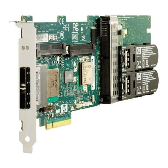
Hardware features In this section Main components on the board ......................... 5 Controller specifications ..........................5 Main components on the board Item ID Description Connector for SAS miniports 1E and 2E (external), each 4x wide Heartbeat LED (flashes green when operating normally and amber if the board has failed) Activity LED for external ports SAS port 3I (internal), 4x wide... - Page 6 More than 3 years Cache size 512 MB (48 MB is used by the onboard processor) For more information about the controller features and specifications, and for information about system requirements, refer to the HP website (http://www.hp.com/products/smartarray). Hardware features 6...
-
Page 7: Overview Of The Installation Procedure
Load the controller driver from EBSU on the Smart Setup media. (To load the driver, select Load OEM Boot Drivers in EBSU. For more information about Smart Setup, refer to the HP Smart Setup Guide on the Smart Setup media.) Run Express Setup. - Page 8 The latest firmware, drivers, utilities, software, and documentation for HP Integrity servers are available on the support page of the HP website (http://www.hp.com/support/itaniumservers). Overview of the installation procedure 8...
-
Page 9: Installing The Controller Hardware
Connecting storage devices........................10 Before beginning the installation Before beginning the installation procedure, visit the HP website (http://www.hp.com/support) to confirm that you have the latest version of each driver and utility file needed. Compare the version numbers of the files there with those of the same files on the Smart Setup media. -
Page 10: Connecting Storage Devices
10) or externally ("Connecting external storage" on page 10). For information about supported drive models, see the controller-specific page on the HP website (http://www.hp.com/products/smartarray). Connecting internal storage Power down the server. Install hard drives, if necessary. If you want to group some of the drives in an array, they must meet the following criteria: They must be of the same type, either all SAS or all SATA. -
Page 11: Sas Cable Part Numbers
Release the tab. Connect the other end of the cable to the SAS input connector of the external storage enclosure. If the enclosure uses a standard SAS 4x connector, insert the cable connector into the enclosure • connector, and then tighten the lock screws on the cable connector. If the enclosure uses a mini SAS 4x connector, pull back the tab on the cable connector, insert •... -
Page 12: Updating The Firmware
To update the firmware on the server, controller, or hard drives, use Smart Components. The most recent version of a particular component is available on the support page of the HP website (http://www.hp.com/support). Some components are also available on the Smart Setup media. -
Page 13: Configuring An Array
Using ACU ............................15 Utilities available for configuring an array Two utilities are available for configuring an array on an HP Smart Array controller in an HP Integrity server: ORCA and ACU. ORCA is a simple utility that is used mainly to configure the first logical drive in a new server before •... -
Page 14: Using Orca
Supported procedures ORCA Creation and deletion of arrays and logical drives Assignment of RAID level Sharing of spare drives among several arrays Assignment of multiple spare drives per array Setting of stripe size Migration of RAID level or stripe size Configuration of controller settings Expansion of an array Creation of multiple logical drives per array... -
Page 15: Using Acu
Using ACU For detailed information about using ACU, see the Configuring Arrays on HP Smart Array Controllers Reference Guide. This document is available on the Smart Setup media or the Documentation CD that is provided in the controller kit. -
Page 16: Installing Device Drivers And Management Agents
The HP Smart Array SAS/SATA Event Notification Service provides event notification to the Microsoft® Windows® Server 2003 64-bit system event log and the HP Integrated Management log. The most recent version of the software component is available on the support page of the HP website (http://www.hp.com/support/itaniumservers). Installation instructions are provided with the component. -
Page 17: Installing Management Agents
If the driver is active, the system responds by displaying cciss. Installing Management Agents The most recent versions of the agents are available on the support page of the HP website (http://www.hp.com/support/itaniumservers). For installation instructions, refer to the downloadable file HP Insight Management Agents for Linux on Integrity Servers provided with the agents. -
Page 18: Upgrading Or Replacing Controller Options
Upgrading or replacing controller options In this section Replacing or adding a battery ......................... 18 Replacing the cache module or controller....................22 Replacing or adding a battery CAUTION: Electrostatic discharge can damage electronic components. Be sure you are properly grounded before beginning this procedure. - Page 19 While holding the battery assembly, tilt the clip until it is at about 30 degrees to the batteries, and then push the clip in line with the clip hinges until the clip detaches from the batteries. The rest of the procedure depends on whether you are replacing a battery or adding one. If you are replacing a battery, continue with the next step.
- Page 20 Position the new battery and the remaining good battery as indicated, and then push them together and slide them until they are aligned. The batteries combine into one unit. Install the battery clip. Position the clip so that the hinges on the clip are next to the appropriate hinge pillars on the batteries.
- Page 21 Position the batteries so that the pegs A on the underside of each battery are in the appropriate holes B on the controller board and pegs C are in slots D. Slide the batteries toward the board bracket until they are firmly seated against the connectors on the cache module.
-
Page 22: Replacing The Cache Module Or Controller
Push the clip firmly at both ends (2) until it clicks into place under the controller board. Reinstall the controller in the server. After installing a battery pack, you might see a POST message during reboot indicating that the array accelerator (cache) is temporarily disabled. - Page 23 Pull the flanges on the battery clip outward (1), and then swivel the clip 180 degrees so that it rests on the batteries (2). Swivel the latches on the DIMM connector outward (1). Slide the battery assembly and the cache module off the controller board (2). The procedure at this point depends on whether you are replacing the controller or the cache module.
- Page 24 Position the batteries so that the pegs A on the underside of each battery are in the appropriate holes B on the controller board and pegs C are in slots D. Slide the batteries toward the board bracket until the connectors on the cache module are firmly seated in the DIMM connector.
- Page 25 Push the clip firmly at both ends (2) until it clicks into place under the controller board. Reinstall the controller in the server. Upgrading or replacing controller options 25...
-
Page 26: Replacing, Moving, Or Adding Hard Drives
Replacing, moving, or adding hard drives In this section Identifying the status of a hard drive ......................26 Recognizing hard drive failure......................... 27 Replacing hard drives ..........................29 Moving drives and arrays ........................32 Adding drives ............................32 Identifying the status of a hard drive When a drive is configured as a part of an array and connected to a powered-up controller, the condition of the drive can be determined from the illumination pattern of the hard drive status lights (LEDs). -
Page 27: Recognizing Hard Drive Failure
Systems Insight Manager, refer to the documentation on the Management CD.) ADU lists all failed drives. • For additional information about diagnosing hard drive problems, refer to the HP Servers Troubleshooting Guide. CAUTION: Sometimes, a drive that has previously been failed by the controller may seem to be operational after the system is power-cycled or (for a hot-pluggable drive) after the drive has been removed and reinserted. -
Page 28: Effects Of A Hard Drive Failure
Effects of a hard drive failure When a hard drive fails, all logical drives that are in the same array are affected. Each logical drive in an array might be using a different fault-tolerance method, so each logical drive can be affected differently. -
Page 29: Replacing Hard Drives
Replacing hard drives The most common reason for replacing a hard drive is that it has failed. However, another reason is to gradually increase the storage capacity of the entire system. If you insert a hot-pluggable drive into a drive bay while the system power is on, all disk activity in the array pauses for a second or two while the new drive is spinning up. - Page 30 drive) and write it to the replacement drive. This process is called automatic data recovery, or rebuild. If fault tolerance is compromised, this data cannot be reconstructed and is likely to be permanently lost. If another drive in the array fails while fault tolerance is unavailable during rebuild, a fatal system error can occur, and all data on the array is then lost.
-
Page 31: Upgrading Hard Drive Capacity
Back up as much data as possible from the logical drive. CAUTION: Do not remove the drive that has the media error. Doing so causes the logical drive to fail. Restore data from backup. Writing data to the location of the unreadable sector often eliminates the error. -
Page 32: Moving Drives And Arrays
Repeat the previous step for the other drives in the array, one at a time. When you have replaced all drives, you can use the extra capacity to either create new logical drives or extend existing logical drives. For more information about these procedures, refer to the HP Array Configuration Utility User Guide. - Page 33 physical drives in the array. During this procedure, the logical drives each keep the same fault-tolerance method in the enlarged array that they had in the smaller array. When the expansion process has finished, you can use the liberated storage capacity on the enlarged array to create new logical drives.
-
Page 34: Diagnosing Array Problems
Diagnosing array problems In this section Controller board runtime LEDs........................34 Battery pack LEDs........................... 35 Diagnostic tools ............................. 36 Controller board runtime LEDs Immediately after the server is powered up, the controller runtime LEDs illuminate briefly in a predetermined pattern as part of the POST sequence. At all other times during server operation, the illumination pattern of the runtime LEDs indicates the status of the controller, as described in the following table. -
Page 35: Battery Pack Leds
LED ID Color LED name and interpretation Green CR506: Command Outstanding LED. The controller is working on a command from the host driver. Green CR505: Controller Heartbeat LED. This LED flashes every 2 seconds to indicate the controller health. Green CR504: Gas Pedal LED. -
Page 36: Diagnostic Tools
Several diagnostic tools provide feedback about problems with arrays. The most important are: • This utility is a Windows®-based diagnostic tool that sends an email to HP Support when it detects any problems with the controllers and attached storage in a system. -
Page 37: Electrostatic Discharge
Electrostatic discharge In this section Preventing electrostatic discharge......................37 Grounding methods to prevent electrostatic discharge ................37 Preventing electrostatic discharge To prevent damaging the system, be aware of the precautions you need to follow when setting up the system or handling parts. A discharge of static electricity from a finger or other conductor may damage system boards or other static-sensitive devices. -
Page 38: Regulatory Compliance Notices
Regulatory compliance notices In this section Federal Communications Commission notice ..................... 38 Modifications............................38 Cables ..............................38 Canadian notice ............................ 38 European Union regulatory notice ......................39 BSMI notice ............................39 Japanese class A notice .......................... 39 Korean class A notice ..........................40 Battery replacement notice ........................ -
Page 39: European Union Regulatory Notice
European Union regulatory notice This product complies with the following EU Directives: Low Voltage Directive 73/23/EEC • EMC Directive 89/336/EEC • Compliance with these directives implies conformity to applicable harmonized European standards (European Norms) which are listed on the EU Declaration of Conformity issued by Hewlett-Packard for this product or product family. -
Page 40: Korean Class A Notice
Batteries, battery packs, and accumulators should not be disposed of together with the general household waste. To forward them to recycling or proper disposal, please use the public collection system or return them to HP, an authorized HP Partner, or their agents. -
Page 41: Acronyms And Abbreviations
Acronyms and abbreviations Array Configuration Utility Advanced Data Guarding (also known as RAID 6) Array Diagnostics Utility BBWC battery-backed write cache DIMM dual inline memory module EBSU EFI-based setup utility extensible firmware interface light-emitting diode ORCA Option ROM Configuration for Arrays PCIe peripheral component interconnect express POST... - Page 42 Smart Array Acronyms and abbreviations 42...
-
Page 43: Index
Index ACU (Array Configuration Utility) 13, 15 electrostatic discharge 37 adding drives 32 environmental requirements 5 Array Configuration Utility (ACU) 13 error messages 27 array controller installation overview 7 European Union notice 39 array expansion 32 Event Notification service 16 array, configuring 13 expanding an array 32 array, moving 32... - Page 44 LEDs, battery pack 35 Taiwan battery recycling notice 40 LEDs, controller 34 temperature requirements 5 LEDs, hard drive 26 troubleshooting 36 logical drive capacity extension 32 logical drive, creating 13 logical drives, maximum number of 5 updating the firmware 12 upgrading drive capacity 31 Management Agents, updating 16 moving an array 32...
Need help?
Do you have a question about the Smart Array P800 and is the answer not in the manual?
Questions and answers