Table of Contents
Advertisement
Quick Links
Revision history
Rev.
Date
Edited by
0.1.1
2008-OCT-07
Csaba Magyar
1.0.17
2009-FEB-25
Csaba Magyar
1.0.18
2009-MAR-28
Miklos Svarcz
1.0.20
2009-APR-15
Csaba Magyar
1.0.21
2009-MAY-25
Csaba Magyar
1.1.1
2009-JUN-10
C.Magyar
1.2.1
2009-JUN-11
C.Magyar
1.2.2.
2009.JUN-12
C. Magyar
1.2.3.
2009.JUN.15
C. Magyar
1.2.5
2009-JUN-30
C.Magyar
1.2.6
2009-AUG-14
C.Magyar
1.2.7
2009-SEP-16
C.Magyar
1.2.8
2009-OCT-14
C.Magyar
1.2.9
2009-OCT-29
C.MAGYAR
1.2.10
1.2.11
2009-12-12
C.Magyar
1.2.12
2010-01-18 -
Z.Borbás
2010--02-17
1.2.13
2010-02-24.
Z.Borbás
1.2.14
2010-03-03
C.Magyar
1.2.15
2010-04-12
C.Magyar
1.2.16
2010-04-15
C:Magyar
1.2.17
2010-06-04
C.Magyar
1.2.18
2010-06-11
C.Magyar
1.2.19
2010-06-29
C. Magyar
1.2.20
2011-02-14
C.Magyar
1.2.21
2011-03-10
C.Magyar
1.2.22
2011-04-29
A.Tremmel
1.2.23
2011-07-06
D. Lopez de
Quintana
1.2.24
2011-07-14
D. Lopez de
Quintana
1.2.25
2011.08.31
D. Lopez de
Quintana
1.2.26
2011.12.31
D. Lopez de
Quintana
1.2.27
2012.02.11
D. Lopez de
Quintana
1.2.28
2012.03.07
M. Switzer
1.2.29
2012.11.22
T. Jozsi
OM-A5-01-1229
Sections affected
ALL – initial revision
1.0.17 – closing revision
1.0.18-finalised version
Troubleshooting
SW revision - update
Reorder
Accommodate changes and review reordering
Edit
Limited features removed
Menu system review
List of accessories
SV cleaning (11.5.1), Result interpretation (sect 6), Reag.cons update,
Fluidic schematics (14.1-3); Measurement principles detailed;
Xb description; measurement methods
Autoloder prep.
Rewording, parameter clean-up, screen-shots, pictures, drawings, re-
structuring, Autosampler, reagent lock
Improved flagging description
Troubleshooting added
Update to SW 1.0.339
XB related functions removed
Screenshot updates, Measurement related troubleshooting temporarily
removed
SV cleaning revised
Reagent filtering method (specs) ultramicro filtered
X-B functions reinserted. Based on review by David Lopez;
nd
based on 2
review by GyA; Vienna sales office removed;
installation by service –> service manual; load qc values added
X-B explanations included along with screenshots; sw versions updated in
the top; "set date and time" removed from installation section; reagent
lock section rephrased; troubleshooting part rearranged; reagent
consumption updated; printout samples updated;
EMC Class A specific information added to section 1.1.3;
Reagent replacement procedure: steps to replace containers added:
section 15.1.11; meas related troubleshooting received hard cleaning; 1
(approval page) added; garbage can icon added (section 1.1.3)
New SV cleaning added to SV cleaning chapter
Update screens; to match FDA release
Intensive review and update for US release.
Added section for Bar Code Symbologies, updated TAB file format,
changed recommendation for shear valve cleaning from 300 to 1200,
updated External Devices settings to add LIS TCP/IP "listener" port
information
Added Indications for Use statement
Qualified sample handling to include only venous blood
Updated performance characteristics
Removed references to refrigerated samples
Added table of background limits
Updated analytical measuring range
Updated Indications for Use and removed references to Research Use
Only (RUO) parameters
Correct Blank Limit and AMR errors
General Update, reagent consumption update
Approved by
Csaba Magyar
Svarcz Miklós
Á. Gyetvai
A. Galgóczi
st
Advertisement
Table of Contents

Related Manuals for Diatron Abacus 5


Summary of Contents for Diatron Abacus 5
- Page 1 OM-A5-01-1229 Revision history Rev. Date Edited by Sections affected Approved by 0.1.1 2008-OCT-07 Csaba Magyar ALL – initial revision 1.0.17 2009-FEB-25 Csaba Magyar 1.0.17 – closing revision Csaba Magyar 1.0.18 2009-MAR-28 Miklos Svarcz 1.0.18-finalised version Svarcz Miklós 1.0.20 2009-APR-15 Csaba Magyar Troubleshooting 1.0.21 2009-MAY-25...
- Page 2 APPROVALS Role Name Date Signature Author Tünde Józsi R&D Director Gábor Farkas Quality Systems Mike Switzer...
- Page 3 Operator’s Manual Revision 1.2.29 Issued: November 22, 2012...
- Page 5 This user manual is intended to give detailed information for end users of the Diatron ‘Abacus 5’ optical hematology analyzer. Descriptions contained herein are relevant to ‘Abacus 5’, software versions: Firmware: 2.66 (1125) PIC sw: Laser sw: ...
-
Page 8: Table Of Contents
Known Limitations ..........................17 2.10 Emergency Situations ........................... 17 Product Support ..........................18 Installation ............................. 20 The ‘Abacus 5’ Analyzer Package Contents .................... 20 The Autosampler Package Contenta...................... 20 General Overview and Principles of Operation ................22 General Overview ..........................22 5.1.1 Measured Parameters .............................. - Page 9 6.7.10 Menu Tree ................................... 42 6.7.11 Safety Access Codes ..............................45 Start Up and Shut Down the ‘Abacus 5’ ................... 46 Start Up and Shut Down Overview ......................46 Starting Up the ‘Abacus 5’ Analyzer ...................... 46 7.2.1 Visual Inspection ................................. 46 7.2.2...
- Page 10 Save Tab File ................................87 10.8.6 Save Raw Data ................................88 10.8.7 Delete ..................................88 Calibration ..........................90 11.1 Calibrating the ‘Abacus 5’ ........................90 11.1.1 View Calibrations ................................. 92 Quality Control ..........................94 12.1 Set QC Reference ..........................94 12.2 QC Measure ............................
- Page 11 12.5 View QC Diagrams ..........................96 12.6 View X-B Data ............................96 12.7 View X-B Diagrams ..........................97 Patients ............................98 Multi-User Mode ........................100 14.1 Types of Users ............................ 100 14.2 Creating a New User ........................... 100 14.3 Deleting or Changing Users ......................... 102 Settings .............................104 15.1 Customize Settings ..........................
- Page 12 17.7 Cleaning the Washing Head ........................ 126 17.8 Software Cleaning Maintenance Functions ..................127 17.8.1 Daily Cleaning ................................128 17.8.2 Cleaning the Measurement System ........................... 128 17.8.3 Extended Cleaning (Hard Cleaning) ........................... 128 17.9 Replacing Reagents ..........................129 Reagent Locking ........................132 The Daily Routine ........................
- Page 13 Figure 20. The Status Display ............................40 Figure 21. ‘Abacus 5’ Main Menu ............................ 42 Figure 22. ‘Abacus 5’ Analyzer Startup and Log On Screens ................... 47 Figure 23. Abacus 5 Shutdown Options ........................... 49 Figure 24. Log Off ................................49 Figure 25.
- Page 14 Figure 43. Control The Autosampler With Info Panel ...................... 69 Figure 44. Results Display and Magnified Scatter Plot ....................70 Figure 45. ‘Abacus 5’ Measurement Process ........................71 Figure 46. ‘Abacus 5’ Result Screen ..........................72 Figure 47. Parameter Information Display ........................73 Figure 48.
- Page 15 Figure 111. Detailed Printout Format ..........................145 Figure 112. Listed Printout Format ..........................146 Table of Tables Table 1. ‘Abacus 5’ Analyzer Parameters......................... 23 Table 2. Diatro•Dil-5P Diluent Information ........................24 Table 3. Diatro•Lyse-5P Information ..........................24 Table 4. Diatro•Diff-5P Information ..........................25 Table 5.
- Page 16 Table 7. ‘Abacus 5’ Analyzer Menu Tree .......................... 45 Table 8. Supported Autosampler Bar Code Reader Symbologies ..................61 Table 9. Sample Identification Information ........................73 Table 10. Normal Range Flags ............................74 Table 11. Linearity Range Flag ............................74 Table 12.
-
Page 18: Indications For Use
WBC, LYM%, LYM#, MON%, MON#, NEU%, NEU#, EOS%, EOS#, BAS%, BAS#, RBC, HGB, HCT, MCV, MCH, MCHC, RDWcv, RDWsd, PCT, PDWcv, PDWsd, PLT and MPV. The Diatron Abacus 5 is indicated for use to identify patients with hematologic parameters within and outside of established reference ranges. - Page 19 To prepare the analyzer for shipping, storage or extended periods of inactivity, please drain the reagents and repackage the ‘Abacus 5’ in its original packaging. Do not expose the ‘Abacus 5’ to direct sunlight, extreme temperature or humidity (>80%). The analyzer operates with chemically and biologically active reagents. Physical contact with these reagents should be avoided.
-
Page 20: Environmental Factors
Ensure there is enough clearance in front of the ‘Abacus 5’ analyzer to open the front panel. Allow enough space if you want to use optional external keyboard, mouse or bar code reader. -
Page 21: Figure 1. Abacus 5 With Autosampler Space Requirements
Placement below the laboratory bench also allows for storage of a spare set of reagents. Never place the reagents above the ‘Abacus 5’ analyzer. Placing reagents above the ‘Abacus 5’ analyzer could result in reagent overflow and spilling. -
Page 22: Weight Requirements
100 Kg (220 lb). Please select a table, laboratory shelf, or other location which can support the weight of the ‘Abacus 5’ with accessories and is free from vibration. -
Page 23: Waste Disposal
2.10 Emergency Situations Always follow all applicable laws and regulations with regard to emergency situations. If the ‘Abacus 5’ needs to be powered off due to an emergency situation (like fire, thunderstorm etc.), follow the procedures in chapter 7.3.4. In case of fire, do not use water to extinguish the fire unless the ‘Abacus 5’ is disconnected... -
Page 24: Product Support
3 Product Support Your sales representative is trained and qualified to answer questions about applications and the operation of the ‘Abacus 5’ analyzer. If you have additional questions regarding the ‘Abacus 5’, please ask for manufacturer support through your sales representative. -
Page 26: Installation
4.1 The ‘Abacus 5’ Analyzer Package Contents After opening the ‘Abacus 5’ analyzer packaging, you will find an accessory box. The analyzer is in a plastic bag in between cushioning protective material. After opening the bag, remove the desiccant packs. The package should contain the following items: ... -
Page 28: General Overview And Principles Of Operation
5 General Overview and Principles of Operation 5.1 General Overview The ‘Abacus 5’ is a fully automated high quality hematology analyzer for in vitro diagnostic use in clinical laboratories. It provides precise and accurate 5-part differential measurement using a laser based optical measurement technology. -
Page 29: Approved Reagents And Control Materials
Using unapproved reagents or controls may cause false flagging or incorrect, inaccurate results. Only genuine Diatron reagents may be used in the ‘Abacus 5’ analyzer. Diatron recommends the use of Diacon 5 control material and Diatrocal calibration material from Diatron. These materials have been specifically assayed for use in the ‘Abacus 5’... -
Page 30: Genuine Diatron Reagents
5.1.3 Genuine Diatron Reagents Only use the genuine Diatron reagents below to ensure proper performance of the ‘Abacus’ analyzer. Reagents are manufactured and provided by Diatron MI Plc., and are for in vitro diagnostic use only. If the eyes or skin come into contact with any of the reagents, flush abundantly with water. -
Page 31: Table 4. Diatro•Diff-5P Information
Diatron reagent code D801-X (X: packaging size 1=100mL) Table 5. Diatro•Hypocleaner CC Information The “Hypocleaner CC” is not an online-reagent (not directly connected to the ‘Abacus 5’). This reagent is aspirated from a sample tube into the ‘Abacus 5’ directly. -
Page 32: Principles Of Operation
This change is sensed by the ‘Abacus 5’ electronics and converted to an electrical pulse. The quantity of pulses is proportional to the number of particles. The intensity of each pulse is proportional to the volume of the particle. The volume distribution diagrams of the particles result in the WBC, RBC, and PLT histograms that measured in femtoliter volume units. -
Page 33: Optical Light Scatter And Diffraction Method
The ‘Abacus 5’ electronics convert these changes to electrical pulses which are gathered and stored for analysis. Five part population discrimination is based on analysis of the two dimensional volume and granularity distribution scatter diagram. -
Page 34: Figure 6. Optical Signal Processing System
Both low and high angles of light scatter are captured by optical sensors, providing the ‘Abacus 5’ analyzer with two independent measurements for each cell crossing the path of the laser beam. Figure 7. Cellular Light Scatter The light scatter data are gathered and plotted as a two dimensional scatter diagram. -
Page 35: Inside The 'Abacus 5' Analyzer
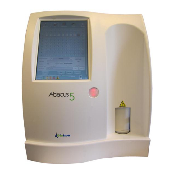
Figure 8. 4DIFF Scatter Diagram 5.3 Inside the ‘Abacus 5’ Analyzer 5.3.1 Front Panel Touch Screen Display Front Panel Sample Rotor START Button Figure 9. Abacus 5 Front Panel... -
Page 36: Back Panel
Sample tubes are placed into a tube adapter inserted on the sample rotor for closed vial or open vial single-tube manual sample processing. The sample tube is rotated from the front of the unit into the inside of the ‘Abacus 5’ for aspiration. -
Page 37: Figure 11. Main Board Back Panel I/O Ports
Main power switch: this is a small switch located next to the power connector. This switch turns off all electrical power to the ‘Abacus 5’ analyzer. Leaving this switch on allows the ‘Abacus 5’ to remain in the standby state. The switch is on when it is in the ‘up’... -
Page 38: Left Side Assembly
Avoid getting liquids on the electrical connectors. The rear panel of the analyzer should be cleaned with a cloth or sponge with alcohol. Serial # and manufacturing label: 5.3.3 Left Side Assembly To access the left or right side assemblies, the side panels must be removed. Please refer to section 17.3 for information about removing the side panels. -
Page 39: Right Side Assembly
Diff-5P buffer is a reservoir for Diatro•Diff-5P reagent. Lyse-5P buffer is a reservoir for Diatro•Lyse-5P reagent. Diluent buffers are reservoirs for Diatro•Dil-5P diluent. Valves 1-44 connect pneumatic components to carry out dilution, reaction, measurement, and waste disposal processes. -
Page 40: Front Assembly
5.3.5 Front Assembly Shear Valve Aspiration Needle Sample Rotor Figure 14. Front Assembly Behind the Front Panel Syringe pumps control the volume and flow rate of reagents through the pneumatic components. Shear valve is an integrated multi-functional valve for segmenting precise volumes of blood. -
Page 42: User Interface
6 User Interface The user interface of the ‘Abacus 5’ analyzer is designed to be intuitive and easy to use, and provide access to all user level functions. You can interact with the ‘Abacus 5’ by using only the touch screen and the virtual on-screen keypad, or by using an external keyboard and mouse (PS2 or USB). -
Page 43: Using The On-Screen Virtual Keypads
For selection of dates, a date keypad is presented. The touch-pad of the ‘Abacus 5’ handles single taps only. The Shift and Symbol keys are ‘sticky’ on the virtual on- screen keypads like the ‘caps-lock’ on a PC key-board. Click/tap on the appropriate buttons to type in the required value. -
Page 44: Using The Graphical User Interface
Figure 18. Date Virtual On-Screen Keypad 6.6 Using the Graphical User Interface The graphical user interface (GUI) of the ‘Abacus 5’ is divided into three main sections. Refer to Figure 19 to see these sections: 1. Quick links to main functions (top section) 2. -
Page 45: Quick Links
Top Navigation Section Screen Body Bottom Section Figure 19. Graphical User Interface Sections 6.6.1 Quick Links The upper part of the GUI is always visible during all operations and presents several quick link buttons. Selecting one of the quick link buttons determines what is displayed in the interactive display area. The selected button is framed on three sides for clear visual feedback. -
Page 46: Entering Information
Entering Information The ‘Abacus 5’ sometimes requires the operator to enter information such as sample ID or patient data. In order to enter information into a data field simply tap or click on it. The data field will change color to yellow indicating that data entry is active for that field. -
Page 47: Start Automated Measurements
Tapping or clicking the ‘Menu’ icon with the main menu graphic displays and allows access to the main menu. The main menu is automatically displayed when the ‘Abacus 5’ analyzer is started up. The main menu icons are arranged in an intuitive and attractive circular design. -
Page 48: Autosampler Control Panel
Double click/tap the time display on the right side of the status display on the bottom of the screen to bring up a panel for adjusting the stored time and date of the ‘Abacus 5’ analyzer. See section 6.7.8 for more information about time and date adjustment. - Page 49 Sarstedt Monovette tubes Standby time: Time period of inactivity before the ‘Abacus 5’ automatically enters standby Offline rinsing frequency: Time period of inactivity before the ‘Abacus 5’ performs an offline rinse to keep the pneumatic system in peak operating condition...
- Page 50 Profile limits: Enter normal ranges for Human, Male, Female, and Alternate 1 and 2 profile limits X-B: Change X-B limits and targets User: Add and manage users of the ‘Abacus 5’ analyzer (only available to administrator users) Delete user: Initiates deletion of a user account...
-
Page 51: Safety Access Codes
Reagent status: Reset levels for individual reagents and waste (or all) for reagent replacement Statistics: Provides operating statistics such as cycle counts, errors, etc. Information: Provides version information for all software items in the ‘Abacus 5’ analyzer Table 7. ‘Abacus 5’ Analyzer Menu Tree 6.7.11... -
Page 52: Start Up And Shut Down The 'Abacus 5
Check for salt stains around the reagent tubing and the reagent containers. Check that the power cord is plugged in both into the back panel of the ‘Abacus 5’ analyzer and to the wall outlet. Empty the waste container. After start up reset the waste level in the “Main menu/ Diagnostics/Reagent status panel”. -
Page 53: Start Up The User Interface
Start Up the User Interface To start up the internal user interface computer of the ‘Abacus 5’ analyzer, flip the standby switch near the top of the rear panel of the ‘Abacus 5’ analyzer to the ‘up’ position. The standby switch springs back to the ‘down’ position after activation. -
Page 54: User Logon
7.2.4 User Logon If the multi-user feature is activated, a user must be logged in before the user interface of the ‘Abacus 5’ can be accessed. You can log in on two different ways: Enter the user ID and password assigned to your account. -
Page 55: Exiting The 'Abacus 5' Analyzer
If the ‘Abacus 5’ was not in use for an extended period of time, the start up of the pneumatic system components can take significantly longer and require more blank measurements. To prevent these problems, use the ‘prepare for shipment’ process when the ‘Abacus 5’ analyzer will be inactive for an extended time. -
Page 56: Shut Down
Prepare for Shipment If the ‘Abacus 5’ analyzer is not to be used for more than 5 days or is being transported to a new location then the ‘prepare for shipment’ procedure should be performed instead the regular shutdown procedure. Click or tap the ‘Exit’... -
Page 57: Figure 27. Connect Distilled Water Panel
It is strongly recommended that the ‘Prepare for shipment’ procedure be used if the analyzer will be inactive for more than five days. Higher temperature or lower humidity decreases the period of time the ‘Abacus 5’ can be idle without performing the ‘Prepare for shipment’ procedure. -
Page 58: Emergency Shut Down
Use the ‘Prepare for shipment’ tube set included with your ‘Abacus 5’ analyzer to perform this step. The system will prime and fully rinse the tubing and pneumatic system with distilled water. This step takes approximately 7 minutes. Do not turn the analyzer off during this step. -
Page 59: Repackaging The 'Abacus 5' Analyzer
The immediate shut-down can be initiated by pressing the standby button near the top of the back panel of the ‘Abacus 5’ analyzer. This is the same button which is used to start up the ‘Abacus 5’ user interface computer. This shuts down the user interface computer without properly shutting down the pneumatic system components. -
Page 60: Sample Measurement
8.1.2 Sampling Depth The ‘Abacus 5’ is equipped with a piercing needle capable of aspirating samples from closed sample tubes. To prevent needle blockage from rubber sample tube cap material and blood particulates, the piercing needle hole is located on the side of the needle rather than at the bottom. Also, the sampling needle is given a safety clearance of two millimeters from the bottom of the tube to prevent accidental breakage of sample tubes. -
Page 61: Open Or Closed Sample Tubes
The viscosity of the blood is very high The ‘Abacus 5’ is unable to aspirate the last 8 mm (0.31 inches) or 0.3 to 0.5 ml of sample volume. Make sure that the sample tube is filled to the sample level line indicated by the tube manufacturer. The anticoagulant not only prevents the coagulation of blood, but also dilutes it. -
Page 62: Sample Types And Modes
‘Abacus 5’ analyzer. Calibration with a calibrator material is not one of the ‘Abacus 5’ sample modes, but a specific procedure that can be accessed from the Calibration icon on the main menu. -
Page 63: Running Samples
Activate or deactivate the automatic generation of sample IDs. If the ‘Autoincrement mode’ check box is checked, then the ‘Abacus 5’ will add 1 to the last sample ID if it was fully numeric or offer ‘0’ if the last sample ID had any non-numeric characters. -
Page 64: Figure 31. Sample Measurement Panel
After starting the measurement the sample door rotates and takes the sample tube inside the ‘Abacus 5’ analyzer. This is a key safety feature of the ‘Abacus 5’ and protects the operator from the sample needle during routine operation. The Start button changes color to red to indicate that the system is busy processing the sample. The sample is aspirated inside the analyzer and returned to the operator when the sampling process is complete. -
Page 65: Automatic Mode
Figure 32. Sample Processing Result Screen The ‘Abacus 5’ analyzer will be ready to take the next sample after it has finished cleaning and preparing for the next sample. The Start button will change to green indicating it is ready to start the next sample measurement. -
Page 66: Figure 33. Autosampler Info And As Panel
Open the AS panel by using the “AS” quick link at the top of the screen. Figure 33. Autosampler Info and AS Panel From the AS panel, you can initiate automated sample measurement in 3 modes: Full Scan mode: o The Autosampler will scan the whole sample tray o The same sample mode (Human, Male, Female, Alternate 1, Alternate 2) will be used for all the samples (NOTE: Alternate 1 and Alternate 2 are sample modes that are different than Human, Male... -
Page 67: Table 8. Supported Autosampler Bar Code Reader Symbologies
8.4.2.1 Supported Bar Code Symbologies Some of the ‘Abacus 5’ analyzer automatic processing modes use the bar code on the sample tube to determine the sample ID of the sample tube. The following bar code symbologies are supported by Autosampler bar code reader:... -
Page 68: Figure 34. Full Scan Automatic Processing Mode
In Full Scan mode it is possible to add more samples to the batch after starting the automated measurement. As usual, an accepted blank is necessary before starting automatic sample processing. Figure 34. Full Scan Automatic Processing Mode On the Full Scan mode panel you can: ... -
Page 69: Figure 35. Full Scan Mode Tray View Progress
The patient ID is not editable in the Full Scan mode as it is automatically set to the default patient. The sample ID is not editable as it is read from the barcode label. If the barcode label is missing or not readable, the ‘Abacus 5’... -
Page 70: Figure 36. Full Scan Mode Tray And List Views
The Autosampler allows the addition of sample tubes to a Full Scan process already in progress. To add more sample tubes, perform the following steps: Click or tap the ‘Stop’ button. The ‘Abacus 5’ will prompt you to wait until the current sample is completed. Acknowledge the message by clicking or tapping the ‘OK’ button. -
Page 71: Figure 37. Free List Mode Selection
rack and sample positions. It is not possible to add additional samples to the batch in free list mode after automated measurement has started. Figure 37. Free List Mode Selection On the Free List mode panel you can: Return to the AS panel to select a different type of automated measurement by using the ‘Back’ function ... -
Page 72: Figure 38 Figure 39. Preparing A Free List
Figure 38 Figure 39. Preparing a Free List As with the Full Scan mode, the Autosampler will scan all the sample positions on the tray and rows with missing racks will be skipped. The Autosampler will only process tube types it recognizes with caps attached. The automated mixing, aspiration, and analysis process is the same as the Full Scan Mode, and the progress can be followed in tray or list view. -
Page 73: Figure 41. Free List Mode Progress: Tray View
Samples mode. An accepted blank measurement is required as with all sample processing. In Selected Samples mode, the ‘Abacus 5’ analyzer will only look for samples in the sample positions selected for analysis. All other samples in sample positions that are not selected will be ignored. If a sample position is selected for processing but contains no sample tube, the sample position will be marked for review. -
Page 74: Figure 42. Selected Sample Mode Panel
To interrupt automatic processing for stat specimens, perform the following steps: Click or tap the ‘Stop’ button. The ‘Abacus 5’ will prompt you to wait until the current sample is completed. Acknowledge the message by clicking or tapping the ‘OK’ button. -
Page 75: Result Display
Figure 43. Control The Autosampler With Info Panel The following is a list of messages from the Autosampler: Home message: o Response after a successful reset o +HOME_XX.YY (The XX.YY is the software revision number) VT zzzzzzz XY: o Vacutainer®... -
Page 76: Printing Reports
Click or tap the Print icon at the top of the screen to send a report (or any displayed screen) to the external printer. 8.7 The Measurement Process The ‘Abacus 5’ analyzer measures 24 parameters of whole human blood samples. Internal dilutions are made to allow measurement of particles in the sample. Manual or automatic mode samples are processed in the same way. -
Page 77: Figure 45. 'Abacus 5' Measurement Process
Figure 45. ‘Abacus 5’ Measurement Process When you present the sample tube and press the Start button, the ‘Abacus 5’ rotates the sample rotor and takes the sample tube inside the analyzer. The piercing needle pierces the sample tube cap (if present) and aspirates approximately 110 µL of primary blood sample. -
Page 78: Result Interpretation
9 Result Interpretation This chapter provides description about interpreting and understanding reports provided by the ‘Abacus 5’ analyzer. 9.1 The Result Screen Figure 46. ‘Abacus 5’ Result Screen The ‘Abacus 5’ analyzer result screen is divided into 4 major areas: 1. -
Page 79: Parameter Information
Table 9. Sample Identification Information 9.3 Parameter Information The parameter information area of the ‘Abacus 5’ analyzer result screen lists information on 24 parameters. Figure 47. Parameter Information Display Each row shows the parameter name, value, flags (normal range, linearity range, and high blank), units, and normal range. -
Page 80: Scatter Diagrams And Histograms
9.3.1 Scatter Diagrams and Histograms The ‘Abacus 5’ analyzer displays the results of the optical measurements in scatter diagram representation. Scatter diagrams represent two-dimensional data. There are two scatter diagrams in the patient report: the 4-DIFF and BASO scatter diagrams. -
Page 81: Figure 49. Result Screen Scatter Diagrams
cell. One portion of this scattered light is proportional to size of the cell; the other is proportional to the complexity of the internal structures in the cell. Cells in a leukocyte sub-population have similar light scattering properties, allowing them to be grouped together and identified separately from other cell types. -
Page 82: Warnings
Figure 51. Warnings Section of Results Screen The ‘Abacus 5’ analyzer provides Warning flags, Morphological flags, and Interpretive messages in the Warnings panel. The following tables describe these flags and messages in detail. It also provides guidance on actions the... - Page 84 Check cleanliness of the reagents and the ‘Abacus 5’. Perform cleaning of the ’Abacus 5’. Repeat blank measurement. See WBC blank is high WBC >...
- Page 85 Flag Meaning Cause Action Check cleanliness of the reagents and the ‘Abacus 5’. Perform flow cell cleaning of the ’Abacus 5’. Repeat blank measurement. BASO blank high More than 100 cells detected during the ’Baso-blank’ procedure. See chapter: 6.1.5 :Pneumatics start and blank measurement Treat BASO result as ‘reduced reliability’.
-
Page 86: Table 13. Warning Flags
There is a (partial) clogging or leakage in the WBC part of Perform cleaning of the ’Abacus 5’. Perform a self-test. WBC vacuum warning measurement system. A faulty/ worn-out pump can create If vacuum problems persist then call for service. -
Page 87: Table 14. Interpretive Flags
Flag Meaning Cause Action The count in the region of (low - high angle scatter of Abacus 5) Perform a manual count on a stained smear. Immature granulocytes where the Immature granulocyte typically located is > 3% of the total WBC count. -
Page 88: Database Functions
10.1 Database Overview The ‘Abacus 5’ analyzer database provides a powerful, easy-to-use method of storing, accessing, and managing patient and sample result information. The database of the ‘Abacus 5’ analyzer is capable of storing up to 100,000 measurement, control and patient records. -
Page 89: Scrolling The Database View
The ‘Abacus 5’ database displays two numerical counters separated by a slash under the left side of the database table. The left number is the number of selected rows, and the right number is the total number of rows in the database. -
Page 90: Manual Selection Of Database Records
Clicking or tapping the same column heading again changes the ascending or descending order of values in the column. 10.4 Manual Selection of Database Records Clicking or tapping on a row in the database display single-selects a row. Clicking or tapping it again de-selects the row. -
Page 91: Statistics
Figure 55. Manage Records Panel All data manipulation actions that change the data stored in the ‘Abacus 5’ database are logged in the ‘Abacus 5’ log. If the multi-user mode is enabled, the name of the operator logged on at the time the data manipulation occurs will also be stored in the log. -
Page 92: Importing
‘Details’ views the detailed result information for all or a selection of imported records. ‘Clear’ removes selected records from the imported records table, but does not permanently remove the cleared records from the stored database file. ‘Back’ ends viewing of imported database information and returns to the ‘Abacus 5’ stored database. -
Page 93: Export
Introduce a USB storage device (USB hard drive, memory stick, etc.) into an available USB port on the back panel of the ‘Abacus 5’ analyzer. Select the directory to store the exported data and press the ‘Ok’ button to start the export. -
Page 94: Save Raw Data
Diatron certified service engineer. Insert a USB data storage device to one of the USB inputs on the back panel of the ‘Abacus 5’ analyzer. Click or tap the ‘Save raw data’ button on the Manage records panel, then enter the correct confirmation password. Click or tap the ‘Ok’... -
Page 96: Calibration
PLT, HGB, MCV, and MPV. To view the calibration functions of the ‘Abacus 5’ analyzer, select the ‘Calibration’ icon on the main menu to display the calibration panel. The Calibration panel displays an option to calibrate the ‘Abacus 5’ analyzer or to view prior calibrations. -
Page 97: Figure 60. Calibration Panel And Calibration Run Result Panel
All applicable laws, regulations, and laboratory practices should be followed in the handling and disposal of calibrator materials. To perform the automated calibration procedure, ensure that the ‘Abacus 5’ pneumatic system is started up and that a valid blank measurement has been accepted. Perform the following steps: ... -
Page 98: View Calibrations
Any calibration can be deleted. Deleting the last calibration causes the ‘Abacus 5’ analyzer to revert to the last accepted calibration. -
Page 99: Figure 62. View Calibration Panel
To delete a calibration, click or tap the ‘Delete’ button. The system will ask you for a confirmation password to avoid accidental deletion of calibration data. The confirmation password is set at the factory to 555, and can be changed by your Diatron certified service engineer. -
Page 100: Quality Control
The advantage of a commercial control material is that is shelf life is much longer than human blood, allowing control of the analyzer for a longer period of time. Controls in the ‘Abacus 5’ are processed in manual mode only. To access the QC panel, select the ‘QC’ icon on the main menu. -
Page 101: Figure 64. Set Qc Reference Panel
Enter the identifying information, and the target values and tolerance ranges for any parameters that are to be controlled with the ‘Abacus 5’ QC system. To exclude a parameter from the QC procedure, leave its target value and tolerance range field empty. Press the ‘Save reference’ button after data entry is completed. -
Page 102: Qc Measure
12.3 View QC References Click or tap the ‘View QC References’ button to see a list of QC lot references stored in the ‘Abacus 5’ analyzer control database. Target values and ranges can be viewed for any stored QC references. -
Page 103: View X-B Diagrams
The X-B moving average is an algorithm which is capable of tracking changes of the accuracy-alternating of the measurements. The algorithm observes the alteration of the derived values which are generally stable. For example the MCV, MCH and MCHC values show the proportion between the blood components. These values fall within narrow limits in human blood therefore these values are able to show the drifting of the device. -
Page 104: Patients
13 Patients The ‘Abacus 5’ analyzer allows the operator to define and store patients in the patient database during manual measurement. Patients can also be predefined while creating a list for one of the automatic processing modes. Select the Patients icon on the main menu to display the Patients panel. -
Page 105: Figure 68. Edit Patient Panel
Figure 68. Edit Patient Panel The ‘Save’ function saves any changes made. To discard any changes made, simply click or tap the ‘Back’ button. -
Page 106: Multi-User Mode
The multi-user mode is disabled by default, and can only be enabled by your Diatron certified service engineer. If you want to use the multi-user mode, ask your Diatron certified service engineer during the analyzer installation (or at any time) to create the first administrator user with the user ID and password you provide. -
Page 107: Figure 69. Logon Panel
Figure 69. Logon Panel Enter your user ID and password, then press or click the ‘Add user by administrator’ button. This will bring up the add user panel. Figure 70. Add User Panel To create a new user, enter a new user ID in the ‘UserID’ text field, then enter the new user password into the ‘Password’... -
Page 108: Deleting Or Changing Users
14.3 Deleting or Changing Users Anyone with a valid administrator account can delete administrator or regular delete users. Regular users do not have privileges to create or delete users. To delete a user, log on with a valid administrator account user ID and password, then click or tap the ‘Menu’... -
Page 109: Figure 73. Settings Panel (Administrator User)
Figure 73. Settings Panel (Administrator User) You can also change the access privileges of a user. Unchecking the ‘Administrator’ check box when an administrator user is selected will change the user to a regular user. Similarly, checking the ‘Administrator’ check box when a regular user is selected will change the user to an administrator user. -
Page 110: Settings
15 Settings The ‘Abacus 5’ analyzer can be tailored to your laboratory’s needs by changing the settings. Click or tap the ‘Settings’ icon on the main menu to access the Settings panel. Figure 75. Settings Panel The options available on the Settings panel are: ... -
Page 111: Laboratory Settings
‘Abacus 5’ Language – select the language that the ‘Abacus 5’ analyzer user interface uses to communicate with the operator. Only English (United States) is available in the US version of the ‘Abacus 5’ analyzer. -
Page 112: System Settings
Automatic LIS – The ‘Abacus 5’ will transmit every measurement result as soon as it is available if this check box is checked. LIS – the ‘Abacus 5’ analyzer will use an Ethernet connection rather than a serial connection of this check box is checked. -
Page 113: Figure 78. System Settings Panel
Database display limit – select All or Last month to change the number of database records displayed in the database panel. Last month only displays the last 30 days of measurement results, and All displays all measurement results stored in the ‘Abacus 5’ database. ... -
Page 114: Units
15.5 Units The Units panel allows the user to choose which units are displayed for certain parameters. The following options are available on the Units panel: HGB unit – choose g/dL or g/L to change the displayed units for the HGB and MCHC parameters. ... -
Page 115: Profile Limits Settings
Figure 80. Printer Settings Panel 15.7 Profile Limits Settings The Profile Limits settings are used to view and modify the normal ranges associated with the ‘Abacus 5’ analyzer’s five sample modes: Human, Male, Female, Alternate 1, and Alternate 2. NOTE: Alternate 1 and Alternate 2 are sample modes that are different than Human, Male and Female, and have user-definable normal ranges. -
Page 116: X-B Settings
Figure 81. Profile Limits Settings Panel 15.8 X-B Settings The X-B panel displays the currently selected X-B constants. Change the values as needed, then click or tap ‘Save’ to save the new values and return to the Settings panel, or select Back to discard any changes and return to the Settings panel. -
Page 117: User Settings
Figure 82. X-B Settings Panel 15.9 User Settings The User Settings panel allows administrators to delete users, or assign administrator rights. Figure 83. User Settings Panel See section 1 for more details on creating, deleting and modifying users. 15.10 Date and Time Adjustment Double-click or tap the time display on the bottom right side of the screen to display a time/date settings panel. -
Page 118: Figure 84. Time/Date Settings
Figure 84. Time/Date Settings The ‘Abacus 5’ analyzer does not support automatic time zone or daylight savings time changes. Please change the time and date manually when necessary. -
Page 120: Instrument Diagnostics
16 Instrument Diagnostics The instrument diagnostics section allows the operator to perform diagnostic procedures, check the operational history of the instrument, set or check the status of the reagents and view stored information about the system. Click or tap the ‘Diagnostics’ button on the main menu to view the available options in the Diagnostics panel. Figure 85. -
Page 121: Figure 86. Self Test Panel
Figure 86. Self Test Panel Initiating a self test will test the key functions and components of the analyzer. The process takes approximately one minute. The individually tested items and their acceptable ranges can be found in the following table. Clicking or tapping any of the individual test items provides detailed information including the item readings, limits and comments. -
Page 122: Log
Offset -5.0 to 5.0 mV -12V -13.0 to -11.4 V Temperature WBC Pre-heater None (LSDACQ v3.0) 34.0 to 38.0C (LSDACQ v3.1) LSDACQ No specification Table 19. Self Test Item Limits If any of the values falls outside the above limits, the software will list the errors on the self test report screen. 16.2 Log The system log provides information for service or troubleshooting purposes. -
Page 123: Reagent Status
The ‘Abacus 5’ analyzer notifies the user when any of the reagents are running low or when the waste container is almost full. If you receive a reagent low notification, check the reagent container and replace it if necessary. Click or tap the ‘Reset Diluent,’... -
Page 124: Statistics
16.4 Statistics This menu item will display cumulative information such as the measurements and number of error events experienced during operation. Statistical data can be only reset by a Diatron certified service engineer. Figure 89. Statistics Panel 16.5 Information This menu item displays the instrument serial number and software versions of various system components. This data is important for maintenance purposes, and your service engineer will ask for this information prior to a service call. -
Page 125: Figure 90. Information Panel
Figure 90. Information Panel... -
Page 126: Maintenance
To ensure reliable operation, regular maintenance is required. This chapter describes necessary procedures and steps required to keep your analyzer in a good operating condition. Only Diatron certified service personnel that have received Abacus 5 service training can resolve major problems that occur during operation. Electrical and moving parts should always be serviced by trained service personnel. -
Page 127: Removing The Side Panels
Always wear safety gloves while performing maintenance actions. 17.4 User Maintainable Parts of the Analyzer There are three user maintenance points inside the ‘Abacus 5’ analyzer: Shear valve: this critical component and is responsible for correct sampling and dilution. -
Page 128: Software Maintenance Functions
17.5 Software Maintenance Functions Maintenance functions can be accessed by clicking or tapping the “Maintenance” main menu item. This opens the maintenance function panel. Figure 93. Software Maintenance Functions Clicking or tapping any of the function buttons initiates the corresponding maintenance functions. The maintenance functions are grouped into the following categories. -
Page 129: Cleaning The Shear Valve
Prime sheath: primes the sheath buffer and optical head with diluent Prime Lyse-5P: primes the Lyse-5P buffer and tubing with Lyse-5P reagent Prime diluent: primes the diluent buffers and tubing with diluent or primes the entire system with diluent (the operator is given a choice by the software maintenance function) Prime all: primes all reagent buffers with their corresponding reagents (the operator is given a choice to perform a full system prime or prime individual buffers sequentially) Fill... -
Page 130: Figure 94. Shearvalve Cleaning Maintenance Function
Figure 94. Shearvalve Cleaning Maintenance Function The ‘Abacus 5’ analyzer asks for confirmation to start the procedure. After clicking or tapping the ’OK’ button the shear valve and the connecting tubing are emptied of liquids. A small amount of liquid may remain inside the tubing and the shear valve. -
Page 131: Figure 96. Removing The Shear Valve Axis Thumbscrew
1. Open the front cover and secure it with the latch. Locate the shear valve in the center of the analyzer. 2. Unscrew and remove the axis thumbscrew that secures the shear valve. Clean the axis thumbscrew with water and wipe it dry. Figure 96. -
Page 132: Cleaning The Washing Head
13. Click/ tap the ‘OK’ button to inform the ‘Abacus 5’ software that you completed the cleaning of the shear valve. The shear valve cleaning maintenance function will check the movement and end positions of the shear valve. -
Page 133: Software Cleaning Maintenance Functions
7. Replace the side cover and the side cover screws. Close the front panel. 17.8 Software Cleaning Maintenance Functions Daily cleaning with Diatro•Hypocleaner CC reagent during shutdown helps to keep the ‘Abacus 5’ analyzer clean and in good operating condition. However, blank measurements results may sometimes still be too high during daily use... -
Page 134: Daily Cleaning
Always remove the rubber cap when performing daily cleaning. After this operation, you can leave the ‘Abacus 5’ analyzer powered on for the rest of the day. It will automatically enter a low power state if left unattended. -
Page 135: Replacing Reagents
17.9 Replacing Reagents The ‘Abacus 5’ analyzer is designed to be able continue running without the need to stop if a reagent container needs to be replaced. To support this feature, internal buffers keep sufficient reagents for one measurement cycle and warns the operator when a reagent is about to run out. -
Page 136: Figure 103. Reagent Replacement Panel
Always follow local laws and regulations governing the disposal of hazardous waste. Figure 103. Reagent Replacement Panel... -
Page 138: Reagent Locking
The reagent locking feature assures you that the ‘Abacus 5’ analyzer always produces quality results and operates optimally by ensuring that only genuine Diatron reagents are used in your ‘Abacus 5’ analyzer. The ‘Abacus 5’ analyzer measuring system and data analysis software are designed to work only with genuine Diatron reagents. -
Page 139: The Daily Routine
The description below assumes that the laboratory works during a single daily shift only. The daily routine: Power-up and start-up the ‘Abacus 5’ analyzer (see Chapter 6.2.2 for details) Check reagent container levels and start obtain new reagents from storage if necessary ... - Page 140 If you perform a whole blood measurement calibration, it is recommended to run a blank measurement before the calibration procedure (see chapter 1). Cleaning: Perform cleaning or hard cleaning if: High blank results are experienced Clogging related flags are consistently appearing with measurement results ...
-
Page 142: Troubleshooting
These are called error messages. The Abacus 5’ analyzer provides additional information in the form of numerical codes that help the operator to identify the root cause of the error. These error codes are important for service personnel. They can interpret the messages and take necessary actions. -
Page 143: Mechanical Problems
Figure 107. Detailed Error Message 20.3 Mechanical Problems Most mechanical problems arise because of some physical blockage of the moving parts. Problems caused by severe blocks are usually accompanied by a grinding noise. The noise is a result of a motor not being able to move, but this does not usually result in mechanical damage to moving parts. -
Page 144: Shear Valve (Sv) Related Errors
Salt build up, or thick salt layer at the bottom or on the inside can block the movement of the needle in the wash head (or the movement of the wash head around the needle) The through hole of the needle in the vertical carriage should be free of salt. ... -
Page 145: Priming Problems
20.4.1 Fluctuating PLT background values When the Abacus 5 is used under increased workload, running even 300 samples a day in 5 hours of continuous operation is possible. Despite built-in maintenance programs, the system may require intensive cleaning from time to time. If you find that blank PLT values are increasing and decreasing unexpectedly, please perform a ‘Hard... -
Page 146: Long, Smeared Population
Go to Main Menu, and click or tap the ‘Maintenance’ button. Click or tap the ‘Hard cleaning’ button in the Cleaning section to initiate the procedure. You will need a syringe (10ml) to dose cleaning liquid into the analyzer’s measuring chambers. The process is described below. 20.4.2 Long, smeared population A long, smeared population with this appearance shows that a key... -
Page 148: Accessories
21 Accessories The following items can be found along with the analyzer. Power cord Reagent tube kit Cleaning tube kit Waste container (20L) Cardboard box for waste container Sample tube adapter Operator’s manual 22 Appendix 22.1 Reagent Consumption Function... -
Page 149: Display Ranges
22.2 Display Ranges Parameter Range Selectable Dimensions 0.00 – 120.00 * 10 /µl or 10 cells/µl, cells/l 0.00 – 120.00 * 10 /µl or 10 cells/µl, cells/l 0.00 – 120.00 * 10 /µl or 10 cells/µl, cells/l 0.00 – 120.00 * 10 /µl or 10 cells/µl, cells/l 0.00 –... -
Page 150: Fluidic System
22.3 Fluidic System Figure 110. Fluidic System Diagram... -
Page 151: Printed Report Formats
22.4 Printed Report Formats Figure 111. Detailed Printout Format... -
Page 152: Figure 112. Listed Printout Format
Figure 112. Listed Printout Format... -
Page 153: Parameter Calculation
22.5 Parameter Calculation Parameter Description Units Calculation Leukocyte (white blood µl or 10 WBC = WBC x WBC MEASURED cells) concentration Calculated from differential percentage and WBC Neutophil, NEU% x WBC Lymphocyte, LYM% x WBC µl or 10 Monocyte, MON% x WBC Eosinophil and EO% x WBC Basophil concentration... -
Page 154: Table 24. Parameter Calculation
Parameter Description Units Calculation Calculated from RDWcv and the distribution width PDWsd Platelet Distribution Width of the platelet histogram at 20% of peak PDWsd = PDWcv x (P ) / 0.56 Derived from same histogram as above Platelet Distribution Width PDWcv = PDW x 0.56 x (P ) / (P... -
Page 155: Specifications
Reagents Diatro•Lyse-5P (5 liter) Diatro•Hypocleaner CC (100 ml) (Emergency cleaner) WBC/BAS dilution - 1:170 Dilution ratios RBC/PLT dilution - 1:21,250 4 Diff dilution - 1:50 Sheath fluid Diluent Control material Diacon 5, Manufacturer: Diatron Quality Control QC diagrams, QC database... -
Page 156: Table 25. Specifications
Item Specification Pathological (diagnostic) flags Lab limits (normal ranges) Flagging Reagents alert (3 measurement prealert-online reagent replacement) Instrumental alerts, internal buffer for reagents Calibration Manual and SW supported automatic mode Languages available English menu and support for other languages Software upgrade Via USB Data storage capacity 100,000 records including flags, scatter- and histograms... -
Page 157: Performance Characteristics
22.7 Performance Characteristics 22.7.1 Precision Device repeatability and reproducibility are defined as a standard deviation (SD) or as a coefficient of variation (CV), whichever is greater. Specifications are provided for primary and derived parameters only. Repeatability Reproducibility/Precision Units Parameter < 0.18 <... -
Page 158: Carryover
22.7.7 Reference Ranges Evaluation of reference ranges for the Abacus 5 hematology analyzer was conducted using a data set of 240 normal human whole blood samples. Of the 240 samples, 120 were from female patients and 120 were from male patients >22 years of age. Diatron recommends each laboratory establish its own reference ranges. -
Page 159: Background Limits
Parameter Unit Lower limit Upper limit /µl 4.50 10.37 14.76 45.40 2.91 12.1 42.90 78.10 0.10 7.00 0.15 1.60 /µl 1.08 3.17 /µl 0.20 0.91 /µl 2.43 7.42 /µl 0.01 0.53 /µl 0.01 0.13 /µl 3.86 5.62 F-3.86 F-5.18 M-3.91 M-5.62 g/dl 11.8... -
Page 160: Interfering Substances
Parameter Units High MCHC g/dl RDWcv RDWsd 1000 cells/µl 30.0 Table 34. Analytical Measuring Range 22.7.10 Interfering Substances The following substances can interfere with parameter measurement and alternate measurement procedures may be required. Parameter Interference > 5 NRBCs/100 WBCs , PLT clumps/large PLTs WBC Count >... -
Page 161: Reagent System
22.8 Reagent System 22.8.1 Diluent Diatro•Dil – 5P diluent Isotonic solution, used to dilute whole blood and quantitative and qualitative determination of RBC, WBC, PLT and HGB concentration 22.8.2 Lyse Reagent 1 Diatro•Lyse - 5P Reagent for stromatolysis of RBC and quantitative determination of WBC 5-part differentiation (LYM, MON, NEU, EOS, BAS) and HGB concentration measurement of human blood. -
Page 162: Tab File Format
22.9 Tab File Format This file format is composed of a header line and consecutive lines containing records selected for saving. Each parameter is selected by the <TAB> (08h) character, allowing easy interfacing or importing into most data processing applications, like Microsoft® Excel. Scatter diagrams and historgrams, flags are NOT saved in this format. -
Page 163: Index
23 Index aperture, 26, 32, 33 BASO, 28, 70, 75, 79, 80, 81 blank, 27, 40, 46, 48, 49, 51, 56, 57, 59, 61, 64, 66, 72, 74, 78, 79, 86, 91, 96, 121, 128, 133, 134, 147 calibration, 23, 36, 44, 47, 48, 56, 90, 91, 92, 93, 134, 139 cleaning, 1, 30, 44, 46, 50, 59, 70, 78, 79, 80, 121, 123, 124, 126, 128, 134, 137, 139, 140, 142 clogging, 78, 79, 80, 136, 137 diluent, 147... - Page 164 needle, 12, 30, 33, 48, 54, 58, 70, 126, 127, 138 NEU, 22, 24, 26, 27, 74, 78, 80, 108, 143, 154 noise, 80, 121, 137 normal ranges, 43, 56, 58, 64, 66, 73, 105, 109 PLT, 22, 23, 24, 26, 43, 48, 70, 75, 76, 78, 79, 81, 90, 108, 139, 143, 147, 154 pressure, 36, 137 printer, 14, 41, 43, 69, 108, 109 QC, 22, 44, 47, 48, 56, 57, 59, 82, 94, 95, 96, 97, 132, 133, 134, 142...
Need help?
Do you have a question about the Abacus 5 and is the answer not in the manual?
Questions and answers