RCF nx series User Manual
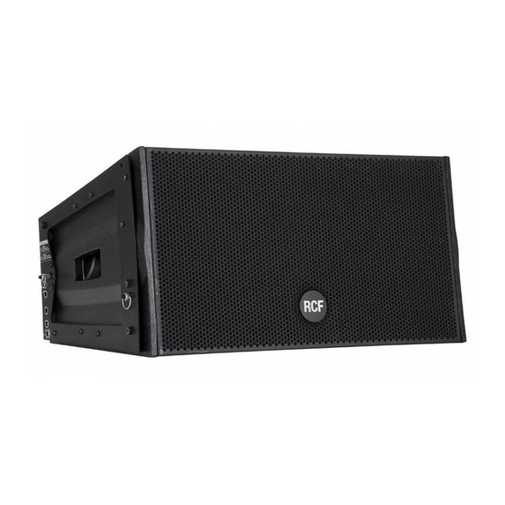
Professional active line array module
Hide thumbs
Also See for nx series:
- Owner's manual (21 pages) ,
- Owner's manual (21 pages) ,
- Owner's manual (17 pages)
Table of Contents
Advertisement
Quick Links
Advertisement
Table of Contents

Related Manuals for RCF nx series


Summary of Contents for RCF nx series
- Page 1 professional ACTIVE LINE ARRAY MODULE Touring audio solutions...
-
Page 2: Safety Precautions
RCF S.p.A. will not assume any responsibility for the incorrect installation and/or use of the product. -
Page 3: Operating Precautions
The NX Series - a new line of active loudspeakers specifically designed to be the everyday tool for rental companies and professional musicians. With its ultra compact design and choice of formats, together with high output levels, NX Series is the answer to a wide variety of production requirements. -
Page 4: Rear Panel Features And Controls
Power on indicator. When the power cord is connected AC POWERCON RECEPTACLE and the power switch is turned on this indicator lights RCF NX series uses a POWERCON locking 3-pole AC mains. green. Always use the specific power cord provided in the package. -
Page 5: Voltage Setup
Now you can turn ON the speaker and adjust the volume control to a proper level. WARNING: Always make sure that the maximum current requirement does not exceed the maximum admitted POWERCON current. In case of doubt call the closest RCF SERVICE CENTRE. VOLTAGE SETUP... - Page 6 Such attachments could act as a sail and topple the system. A single NX L23-A may be used on a tripod stand (AC S260) or on a pole (AC PMA) over its NX Series subwoofers. The use of a subwoofer is recommended for applications requiring more low-frequency power and extension.
- Page 7 english DOUBLE NX L23-A ON A STAND The NX L23-A is designed so that a pair of speakers may be safely mounted onto a pole or tripod stand. 1) Place the speakers on the pole or tripod one at a time. Be sure to lock the two speakers together using its rigging hardware.
-
Page 8: General Rigging Warnings And Safety Precautions
To better comprehend in which safety range the mechanics are working a simple introduction is needed: NXL23-A mechanics are built with certified UNI EN 10025-95 S 235 JR Steel. RCF prediction software calculates forces on every single stressed part of the assembly and shows the minimum safety factor for every link. -
Page 10: Rigging Procedure
english THE NX L23-A FLY BAR THE NX L23-A FLY BAR FEATURES: FRONT FLYING BRACKET Front mounting. QUICK LOCK PIN HOLE Front mounting (to be used to lock the front bracket before installation). REAR BAR HOLE Front mounting. REAR MOUNTING POSITION FLYING BRACKET QUICK LOCK PIN HOLE Rear mounting position. - Page 11 english 2) Connect the second pin on the front bracket to make sure that the connecting bracket is vertical. 3) Connect the front bracket to the first NX L23-A cabinet using 2 quick lock pins. 4) Reverse and connect the 2 rear bracket to the fly-bar using 2 quick lock pins.
-
Page 12: Rcf Shape Designer Software
This discussion represents, of course, just a basic approach. Given the infinite variety of venues and performers, users will find themselves needing to solve specific problems in specific situations. RCF Shape Designer software designed to help calculate optimum splay angles, aiming angles, and fly-bar pick points (crucial in aiming the array) for a given venue, will be explained later in this Guide. - Page 13 USING RCF SHAPE DESIGNER SOFTWARE Once you have installed RCF Shape Designer, it will be visible as a shortcut in All Programs via your Windows Start button. A single click on the RCF Shape Designer tab will open the following page:...
- Page 14 english Filling the blank tabs it’s possible to start the program. ENTERING VENUE DATA For best results, planes should be used as follows: FLOOR is used to simulate the main floor area from the stage to a rear bleacher or boundary. PLANE 1 is used to simulate any audience continuation behind FLOOR (e.g.
-
Page 15: Array Installation
english COVERAGE Specify the horizontal coverage distances from the front of the array. ARRAY INSTALLATION Select either Suspended or Stack in the Array installation section to determines how the array is supported. In Suspended mode the grid is suspended and cabinets are attached beneath. In Stack mode the grid forms a base and cabinets are placed on top. - Page 16 RCF SHAPE DESIGNER RESULTS VENUE PAGE - Graphical representations of the array and the venue - Aiming splay angle between each pair of enclosures ARRAY PAGE - Height of the array and trim height to the bottom of the array from the floor...
- Page 17 english MECHANICS PAGE - Cluster Mechanical specifications - Mechanical safety factors NXL 23-A Flown NXL 23-A PROCESSOR PAGE - DSP preset configuration...
-
Page 18: Manual Mode
MANUAL MODE RCF Shape Designer works in either of two basic ways: - AUTOMATIC MODE (default setting): The RCF Shape Designer will select the optimum enclosure splays, array aiming angle, fly-bar pick point and DSP preset configurations. - MANUAL MODE: This provides a partial control over the array’s configuration. The enclosure splays can be increased with a progression of 2°... -
Page 19: Optimizing The Array
english OPTIMIZING THE ARRAY Once the design (number of elements and vertical splay angles) has been designed using Shape Designer software, you can effectively optimise the array depending on the environment and the application by driving it using different DSP presets stored onboard. Typically arrays are divided in two or three zones depending the design and size of the array. -
Page 20: Low-Frequency Strategies
english LOW-FREQUENCY COUPLING EFFECTS While wave-guides provide isolated control over various mid- to high-frequency coverage areas, the low-frequency section of a NX L23-A array still requires mutual coupling - with equal amplitude and phase - to achieve better directionality. Low-frequency directionality is less dependent on the array’s relative splay angles and more dependent on the number of elements of the array. - Page 21 english NX L23-A GROUND STACKED NX L23-A loudspeakers can be stacked on top of NX subwoofers with the optional AC STACKING / NX L23-A adapters. 1) Insert the optional AC STACKING / NX L23-A adapters on subs as shown in the picture.
- Page 22 english 3) Connect front bracket of the first NX L23-A cabinet using 2 quick lock pins. 4) The baffle of the bottom box in a stacked array does not necessarily have to be parallel to the stage or the array frame. It can be tilted up or downward if desired.
-
Page 23: Technical Specifications
TECHNICAL SPECIFICATIONS ACOUSTICAL NX L23 - A Frequency response 60 Hz - 20 kHz 133 dB Max SPL 100° Horizontal coverage angle Vertical coverage angle 15° max, depending on configuration Compression Driver 3 x 1.0” neo, 1.75” voice coil Midrange 12”...
Need help?
Do you have a question about the nx series and is the answer not in the manual?
Questions and answers