Avid Technology airspeed 5000 Setup Manual
Hide thumbs
Also See for airspeed 5000:
- Administrator's manual (211 pages) ,
- Setup manual (138 pages) ,
- Upgrade manual (26 pages)
Table of Contents
Advertisement
Quick Links
Advertisement
Table of Contents

Related Manuals for Avid Technology airspeed 5000


Summary of Contents for Avid Technology airspeed 5000
- Page 1 Avid ® AirSpeed ® 5000/ AirSpeed l 5500 Setup Guide...
-
Page 2: Legal Notices
Legal Notices Product specifications are subject to change without notice and do not represent a commitment on the part of Avid Technology, Inc. This product is subject to the terms and conditions of a software license agreement provided with the software. The product may only be used in accordance with the license agreement. - Page 3 Permission to use, copy, modify, and distribute this software and its documentation for any purpose and without fee is hereby granted, provided that the above copyright notice appear in all copies and that both that copyright notice and this permission notice appear in supporting documentation.
- Page 4 MERCHANTABILITY or FITNESS FOR A PARTICULAR PURPOSE. See the GNU Lesser General Public License for more details. Portions copyright © 2012 Avid Technology, Inc. Attn. Government User(s). Restricted Rights Legend U.S. GOVERNMENT RESTRICTED RIGHTS. This Software and its documentation are “commercial computer software” or “commercial computer software documentation.”...
- Page 5 News material provided by WFTV Television Inc. Avid AirSpeed 5000/ AirSpeed | 5500 Setup Guide v2.8 • 9329-65456-00 Rev A • March 2015 (3/2615) This document is distributed by Avid in online (electronic) form only, and is not available for purchase in printed form.
-
Page 6: Table Of Contents
Drive Array and Slot Locations (2-Channel Models) ..... 26 Avid AirSpeed 5000 / AirSpeed | 5500 Server - Rear Panel ....27 System Drives . - Page 7 Replacing the Video I/O Board into the Chassis ......42 Installing AirSpeed 5000 / AirSpeed l 5500 Hardware in a Rack ....46 Rack-mount Requirements.
- Page 8 Loading the Windows 7 Pro Embedded Restore Image ....107 Installing AirSpeed 5000 Server Software ....... 112...
- Page 9 Configuring the Server for Record and Playback ......116 Monitor Application..........116 Accessing the Knowledge Base .
- Page 10 Cables ............141 Canadian Notice (Avis Canadien) .
-
Page 12: Using This Guide
Media can be captured directly into Avid Unity workspaces unattended, freeing the Avid editing system for editing. Use the Avid editing system to edit the captured media into sequences and send the sequence back to the AirSpeed 5000 / AirSpeed 5500 for playout. -
Page 13: Symbols And Conventions
Symbols and Conventions Symbols and Conventions Avid documentation uses the following symbols and conventions: Symbol or Convention Meaning or Action A note provides important related information, reminders, recommendations, and strong suggestions. A caution means that a specific action you take could cause harm to your computer or cause you to lose data. -
Page 14: If You Need Help
If You Need Help If You Need Help If you are having trouble using your Avid product: 1. Retry the action, carefully following the instructions given for that task in this guide. It is especially important to check each step of your workflow. 2. -
Page 15: Avid Airspeed 5000 / Airspeed | 5500 Server Overview
This guide covers everything you need to know to unpack, install and configure your AirSpeed 5000 or AirSpeed 5500 server hardware and software. This chapter provides an overview of the AirSpeed 5000 or AirSpeed 5500 server, starting with a topic on how to unpack and inspect your server. For more information, see “Unpacking and... -
Page 16: Unpacking And Inspecting Your Server
Avid recommends that you keep all packaging materials for at least 90 days. If you need to return a server to Avid Technology, Inc., the server and all components must be repackaged in its original packaging material to ensure that there is no damage during shipment. -
Page 17: Verifying Components
Based on your order, you will have one of these servers: - AirSpeed 5000 or AirSpeed 5500 Server, Base (4-channel model) - AirSpeed 5000 or AirSpeed 5500 Server, MPEG-2 HD (4-channel model) - AirSpeed 5000 or AirSpeed 5500 Server, AVC-Intra (4-channel model) -
Page 18: Inspecting Components For Damage
Unpacking and Inspecting Your Server AirSpeed 5000 / AirSpeed 5500 Component List Part Name Customer Letter Health and Safety Guide If you are missing any of these components, contact Avid Customer Support before proceeding. ReadMe files are not in the box. They can be found online. You should always check online for the most up-to-date release notes or ReadMe because the online version is updated whenever new information becomes available. -
Page 19: Airspeed 5000 / Airspeed | 5500 Server Hardware Components
ReadMe. The Windows Product Key Certificate of Authenticity is located to the top-right-front corner of the Avid AirSpeed 5000 or AirSpeed 5500 server. Be sure to write down this number, and use it to activate your Windows 7 Operating System. - Page 20 Five (5) media drives for storing data. The size of the each media drive is shown models) on the front of the drive. • Two (2) system drives. The Avid AirSpeed 5000 or AirSpeed 5500 uses two externally accessible, mirrored system drives for the operating system and application software. •...
-
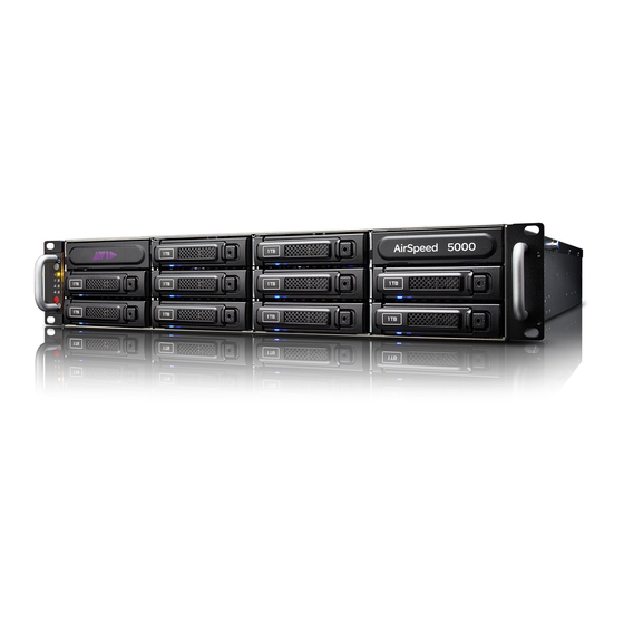
Page 21: Avid Airspeed 5000 / Airspeed | 5500 Server - Front Panels
Avid AirSpeed 5000 / AirSpeed | 5500 Server - Front Panels The front of the Avid AirSpeed 5000 or AirSpeed 5500 server provides access to ten (10) media drives for 4-channel model servers. 2 channel models servers contain five (5) media drives. Both models contain activity LEDs, an error LED, and the Power and Reset buttons. -
Page 22: Determine Media Drive Health By Viewing Led Status
AirSpeed 5000 / AirSpeed | 5500 Server Hardware Components Media Drive Example Drive carrier latch Drive lock Fault LED (red) Power/Activity LED (blue) • The left Power/Activity LED (blue) is solid when a drive has power and flashes when the drive is in use. -
Page 23: Server Front Panel And Led Control Panel
For information on removing media drives, see the topic “Removing and Replacing Media Drives” (for your 2-channel or 4-channel model) in the AirSpeed 5000 Administrator’s Guide: Server Front Panel and LED Control Panel The server has two buttons (Power and Reset). Depending on the LED Control Panel version for your server (Version 1, or Version 2), you will have either 4 or 5 LEDs located on the left rack ear next to the front panel. - Page 24 AirSpeed 5000 / AirSpeed | 5500 Server Hardware Components Server Front View and LED Control Panels LED Control (version 2) LED Control Panel (version 1) AIRSPEED 5000 AIRSPEED 5000 The following table describes the LED Control Panels shown in the previous figure.
-
Page 25: Drive Array And Slot Locations (4-Channel Models)
The LSI MegaRAID Storage Manager is a RAID utility that allows for viewing and management of disks in your media array. If your AirSpeed 5000 server OS image is later than version 6, it will not have the LSI MegaRAID Storage Manager software pre-installed. Earlier AirSpeed 5000 software versions had this software pre-installed on the server. -
Page 26: Drive Array And Slot Locations (2-Channel Models)
The LSI MegaRAID Storage Manager is a RAID utility that allows for viewing and management of disks in your media array. If your AirSpeed 5000 server OS image is later than version 6, it will not have the LSI MegaRAID Storage Manager software pre-installed. Earlier AirSpeed 5000 software versions had this software pre-installed on the server. -
Page 27: Avid Airspeed 5000 / Airspeed | 5500 Server - Rear Panel
Avid AirSpeed 5000 / AirSpeed | 5500 Server - Rear Panel The rear panel AirSpeed 5000 or AirSpeed 5500 server provides access to the power supplies, system drives, video port, 1 gigabit (Gb) Ethernet ports, serial port (not used), and four USB connectors for the keyboard, mouse, and so on. -
Page 28: System Drives
AirSpeed 5000 / AirSpeed | 5500 Server Hardware Components System Drives There are two system drives accessible from the rear of the AirSpeed 5000 or AirSpeed 5500 server. The top drive is Port 0, and the bottom drive is Port 1. These two drives are mirrored, and... -
Page 29: Ethernet Ports
Power Supply 1 Ethernet Ports The AirSpeed 5000 or AirSpeed 5500 Server comes equipped with four Ethernet connectors. Although all four are functional, we currently support the use of only two of these connectors (GigE Ports labelled LAN3 and LAN4) in a redundant configuration for Shared storage (ISIS). -
Page 30: Usb Ports
There are four USB ports located on the rear of the Avid AirSpeed 5000 or AirSpeed 5500 server. USB ports (2) LAN2 LAN4 LAN1 LAN3 USB ports (2) VGA Port There is one VGA port located on the rear of the Avid AirSpeed 5000 or AirSpeed 5500 server. LAN2 LAN4 LAN1 LAN3 Video (VGA) port... -
Page 31: Pci-E Card Slots
Video I/O 1 Video I/O 2 Multi I/O Expansion Card 3 LSI Mega RAID Controller 4 The following table lists the boards that are available in the AirSpeed 5000 or AirSpeed 5500 server. PCI Slot Interface Description Video I/O Card 1 The top Video I/O card in Slot 1 is identified as Video I/O Card 1 and is used for connecting video. -
Page 32: Multi I/O Expansion Panel - Rear View
AirSpeed 5000 / AirSpeed | 5500 Server Hardware Components Multi I/O Expansion Panel - Rear View The included Multi I/O Expansion Panel is required if you plan to use any of the following functionality: • GPIO • LTC Output •... -
Page 33: Installing The Airspeed 5000 / Airspeed | 5500 System
Installing the AirSpeed 5000 / AirSpeed | 5500 System This chapter describes how to install an AirSpeed 5000 or AirSpeed 5500 server on your site. Topics in this chapter include: • Installing Codecs On Your Video I/O Board (2-Channel Models Only) •... -
Page 34: Installing Codecs On Your Video I/O Board (2-Channel Models Only)
HD or AVC-Intra codec modules to the Video I/O board, and then replacing the Video I/O board in the server. The following topics are available: • AirSpeed 5000 Codec Module Kit Contents (2-Channel Models) • Electrostatic Discharge Precautions • Codec Module Installation Checklist (2-Channel Models) •... -
Page 35: Airspeed 5000 Codec Module Kit Contents (2-Channel Models)
Installing Codecs On Your Video I/O Board (2-Channel Models Only) AirSpeed 5000 Codec Module Kit Contents (2-Channel Models) For all AirSpeed 5000 or AirSpeed 5500 2-channel model servers, there are two codec modules that must be installed prior to rack mounting your server. Depending on which 2-channel model server you have ordered, these kits provide your AirSpeed 5000 or AirSpeed 5500 server with either MPEG-2 HD or AVC-Intra hardware capabilities. -
Page 36: Codec Module Installation Checklist (2-Channel Models)
Removing and Replacing the Server Main Cover (2-Channel Models) The AirSpeed 5000 or AirSpeed 5500 server must be operated with the chassis cover in place to ensure proper cooling. However, you will need to remove the main cover to remove the Video I/O board, and add the appropriate codec modules to it. -
Page 37: Removing The Video I/O Board (2-Channel Models)
In order for you to insert the Codec modules onto Video I/O board, you must first remove the Video I/O board from the AirSpeed 5000 or AirSpeed 5500 2-channel model server. For future reference, note that VIO 1 is located in the top Video I/O board slot in the chassis: Make sure the system is offline and powered down before removing the Video I/O board. - Page 38 Installing Codecs On Your Video I/O Board (2-Channel Models Only) 5. Loosen the thumbscrews on the back cover, and slide the cover back to remove it from the chassis. The following diagram shows the location of the two (2) thumbscrews on the rear of the server.
- Page 39 Installing Codecs On Your Video I/O Board (2-Channel Models Only) 7. To disconnect the Video I/O board 1 (VIO 1), do the following: a. Remove the Power Harness (yellow and black cable) from the Video I/O board. Power Harness (yellow and black) b.
- Page 40 Installing Codecs On Your Video I/O Board (2-Channel Models Only) 8. Release the Hold Down Bracket using the thumbscrews, and then slide it out of the chassis. Hold Down Bracket and thumbscrew 9. Remove the Board Locking Bracket by loosening the thumbscrews, and sliding the bracket up, and out of the chassis.
-
Page 41: Attaching The Codec Modules To The Video I/O Board
Installing Codecs On Your Video I/O Board (2-Channel Models Only) Attaching the Codec Modules to the Video I/O Board This topic contains information on how to attach two (2) codec modules to the Video I/O board. This procedure applies to both the MPEG-2 HD and the AVC-Intra codec module kits. To attach the Codec modules to the Video I/O board: 1. -
Page 42: Replacing The Video I/O Board Into The Chassis
1. Observe the safety precautions described in “Electrostatic Discharge Precautions” on page 35 and “Safety and Regulatory Information” in the AirSpeed 5000 / AirSpeed 5500 Setup Guide. 2. Gently replace Video I/O board (VIO 1) into the top riser card slot. - Page 43 Installing Codecs On Your Video I/O Board (2-Channel Models Only) 4. Reattach the SATA and Power cables for the Video I/O board (VIO 1) as follows: a. Reattach the Power Harness (yellow and black cable) to the Video I/O board. b.
- Page 44 Installing Codecs On Your Video I/O Board (2-Channel Models Only) 5. Replace the Hold Down Bracket by sliding it back into place. Once in place, tighten the thumbscrews. Lift the LSI cable that goes along the side of the chassis, so that the Hold Down bracket sits at the bottom of the chassis in it’s slot, then, tighten the thumbscrews.
- Page 45 Otherwise, you can rack mount your system now, connect all peripherals, and power on the server after it has been rack mounted, and then perform system diagnostics later. For more information, see “Installing AirSpeed 5000 / AirSpeed l 5500 Hardware in a Rack” on page...
-
Page 46: Installing Airspeed 5000 / Airspeed L 5500 Hardware In A Rack
The rack-mounting kit requires inner slide rails be mounted to the AirSpeed 5000 or AirSpeed 5500 server and the outer slide rails are mounted to the rack. Once both the inner and outer rails are in place, slide the server with the inner rails attached into the outer rails. -
Page 47: Rack-Mount Requirements
Make sure your rack enclosure is stable enough to prevent tipping over when one or more Avid AirSpeed 5000 or AirSpeed 5500 servers are extended on the sliding rails. •... -
Page 48: Positioning The Server In The Rack
AirSpeed 5500 in the rack. To position the server in the rack enclosure: Select a position in the rack where the AirSpeed 5000 or AirSpeed 5500 server is at the proper baseline position. Positioning the Avid AirSpeed 5000 l AirSpeed 5500... -
Page 49: Attaching Inner Slide Rails To The Server
Installing AirSpeed 5000 / AirSpeed l 5500 Hardware in a Rack 2. Press the spring clip on the inner slide rail as shown in the illustration. The blowup of the spring clip shown in the illustration is on the bottom side of the slide rail. -
Page 50: Attaching The Outer Rails To A Square-Hole Rack
Installing AirSpeed 5000 / AirSpeed l 5500 Hardware in a Rack 2. Secure the inner slide rail to the server with two of the small screws. You might find more screws in the rail kit than is needed, and described in this procedure. - Page 51 Installing AirSpeed 5000 / AirSpeed l 5500 Hardware in a Rack 2. Slide the square tabs through the holes in the front, vertical rack-mounting rail. Positioning the Outer Slide Rail with the Front Rack-Mounting Rail 3. Push the outer rail towards the outside of the rack, to secure the outer rail in place Insert the Outer Slide Rail to the Front Rack-Mounting Rail 4.
-
Page 52: Attaching The Outer Rails To A Round-Hole Rack
Installing AirSpeed 5000 / AirSpeed l 5500 Hardware in a Rack 5. Secure the rear outer slide rail bracket assembly to the rear mounting rail as you did for the front rack-mounting rail. Securing the Outer Slide Rail to the Rear Rack-Mounting Rail 6. - Page 53 Installing AirSpeed 5000 / AirSpeed l 5500 Hardware in a Rack To attach the outer slide rails to the rack with round holes: 1. Locate the four Round Hole adapters (which ship in the accessory kit's plastic bag, not in the rack mount kit box) and position the adapter on the end of the outer slide rail bracket assembly as shown in the following illustration.
- Page 54 Installing AirSpeed 5000 / AirSpeed l 5500 Hardware in a Rack 3. Slide the outer slide rail bracket assembly onto the side rack-mounting rail so that the Round Hole adapter is over the rack rail. You should have someone helping you hold the slide rails level while you are positioning them in the rack.
-
Page 55: Securing The Server In A Rack
AirSpeed 5000 or AirSpeed 5500 server front panel align with the holes in the front mounting rail. 3. From the front of the rack enclosure, insert the large screws through the AirSpeed 5000 or AirSpeed 5500 server and front mounting rail, and tighten. -
Page 56: (Option) Installing The Multi I/O Expansion Panel In A Rack
Installing AirSpeed 5000 / AirSpeed l 5500 Hardware in a Rack (Option) Installing the Multi I/O Expansion Panel in a Rack This topic contains information on how to install the Multi I/O Expansion Panel in a rack. Depending on your signal needs for your site, you must decide whether to use the Multi I/O Expansion Panel. -
Page 57: Installing The Drives In The Server
Fault LED (red) Power/Activity LED (blue) When you are installing drives in the Avid AirSpeed 5000 or AirSpeed 5500 server, begin the installation at the bottom of a column of drives. Make sure the first drive you install is level and flat as you insert it into the server. -
Page 58: Cabling The Server
Cabling the Server Cabling the Server Once the AirSpeed 5000 or AirSpeed 5500 server is securely installed in the rack, and the drives are installed, you are now ready to connect the appropriate cables to the rear panel of the server to the external devices for your particular site. -
Page 59: Airspeed 5000 / Airspeed L 5500 Server Connection Information
AirSpeed 5000 / AirSpeed l 5500 Server Connection Information The rear panel Avid AirSpeed 5000 or AirSpeed 5500 server provides access to the power supplies, system drives, video (VGA) port, 1 gigabit (Gb) Ethernet ports, and six USB ports for the keyboard, mouse, and so on. -
Page 60: Multi I/O Expansion Panel Connection Information
• LTC Output • More than 1 LTC Input Multi I/O Expansion Panel - Rear View LTC In These ports are Ports not used AIRSPEED 5000 MULTI I/O GPIO RS-422 EXPANSION GPIO Port Genlock Multi I/O Expansion RS-422 Ports LTC Out... -
Page 61: Connecting To The Multi I/O Expansion Ports On The Server
Cabling the Server Connecting to the Multi I/O Expansion Ports on the Server Make sure there is adequate space to run and connect the Multi I/O Expansion cables to the rear of the unit. Since, there is no power connection on the Multi I/O Expansion Panel, simply connect it to the server chassis using the two Multi I/O Expansion cables that were supplied with your server. -
Page 62: Connecting Sdi Video Inputs And Outputs
Cabling the Server If your site does not require GPIO, or additional LTC capabilities, you can use the Reference and LTC breakout cable (7070-30344-00), and the Serial Breakout cable (7070-30394-00), as shown in the following illustration, to connect to the Multi I/O Expansion Ports on the rear of the server: Connecting SDI Video Inputs and Outputs The SDI Video connections are marked on the rear of the server. -
Page 63: Connecting Sdi Video Inputs
The four SDI Video Input connections are marked on the rear of the server. Both AirSpeed 5000 and AirSpeed 5500 2-channel model servers only contain one Video I/O card. Therefore, the Video IN 3 and Video IN 4 connections are not available on 2-channel model servers. -
Page 64: Connecting Auxiliary Monitor Outputs
2. Connect the SDI output signal to an outgoing SDI output (one of the four labeled Video OUT1-4 in the diagram) on the server. Both AirSpeed 5000 and AirSpeed 5500 2-channel model servers only contain one Video I/O card. Therefore, the Video OUT 3 and Video OUT 4 connections are not available. - Page 65 (labeled Monitor OUT 1-4 in the diagram) on the rear of the server. Both AirSpeed 5000 and AirSpeed 5500 2-channel model servers only contain one Video I/O card. Therefore, the Monitor OUT 3 and Monitor OUT 4 connections are not available.
-
Page 66: Connecting Video Reference
Connecting LTC This topic contains information on how to connect LTC to the AirSpeed 5000 or AirSpeed 5500 server. Depending on your site’s needs, there are two methods to connect LTC to your server. No matter what choice you have decided on (cable or Multi I/O Expansion Panel), the LTC signal will always be the same. -
Page 67: Converting Bnc Connectors To Xlr
Multi I/O Expansion Panel. Converting BNC Connectors to XLR On the AirSpeed 5000 or AirSpeed 5500 server, the LTC OUT connections require BNC. However, if you want to convert from a BNC connection to an XLR connection, you must purchase BNC to XLR adapters. -
Page 68: Connecting Ethernet
LAN3 and LAN4) in a redundant configuration for Shared storage (ISIS). For more information on connecting the AirSpeed 5000 or AirSpeed 5500 server as an ISIS 5000 or ISIS 7000 client in a dual port network, refer to the topic “Dual Port Network Connections” in the Avid ISIS Client Guide. -
Page 69: Connecting Serial
Connecting Serial The following topic describes how to connect a serial controller device (such as an automation system or edit controller) to the AirSpeed 5000 or AirSpeed 5500 server or the Multi I/O Expansion Panel. For details on each RS-422 connector with signals, see “RS-422 Serial Remote DB9 Connector... -
Page 70: Connecting A Gpio Device
Connect the other end of the serial cables to your RS-422 devices. Connecting a GPIO Device The following topic describes how to connect a GPIO device to the AirSpeed 5000 or AirSpeed 5500 server via the Multi I/O Expansion Panel. -
Page 71: Connecting A Keyboard, Monitor, And Mouse
USB port on the server. To connect a keyboard, monitor, and mouse to the server: 1. Install your KVM switch in a suitable slot next to the AirSpeed 5000 or AirSpeed 5500 server in the rack. -
Page 72: Connecting The Power Cords
Connecting the Power Cords Connecting the Power Cords The last step you must perform when cabling up your AirSpeed 5000 or AirSpeed 5500 server is to connect the power cords. Two U.S. IEC power cords are shipped with the unit. If your local power distribution is not compatible with the supplied cords, you must provide your own IEC power cables that are compatible with your country’s power system. -
Page 73: Turning On The Server
Turning On the Server Turning On the Server When you turn on the power to your AirSpeed 5000 or AirSpeed 5500 server, you must do it in the following order so that it will see all of its connected components. -
Page 74: Performing System Diagnostics
Performing System Diagnostics Performing System Diagnostics The AirSpeed 5000 Hardware Test is a diagnostic program that is designed to test the Avid-specific hardware components present on the AirSpeed 5000 or AirSpeed 5500 server. Specifically, the diagnostic program can be used to verify that the Avid hardware is working properly and it can confirm compatibility with external audio and video devices. -
Page 75: Diagnostic Window Explained
Performing System Diagnostics Diagnostic Window Explained The diagnostic window is divided into following sections: • The Information section displays revision and identification information about the Avid hardware, including Base Board Information, and VIO Board information. • The Hardware Test allows you to select the loopback cables that are connected to your system. -
Page 76: Reviewing Hardware Information
Airspeed5000Test.exe. Or, from the desktop, locate the Support Apps folder, and select Airspeed5000Test.exe The Avid AirSpeed 5000 Hardware Test dialog box opens. The version shown in the title bar following screen example is [00.32]. You might have a later version, and therefore, your values might be different. - Page 77 Part Number FPGA_C Revision CPLD_N Revision Codec Slot 1 - If your server is an AirSpeed 5000 model (with older MSQ201 codecs), “MPEG-2” displays. If your server is an AirSpeed 5500 model (with newer MSQ211 codecs), “MPEG-2/XAVC” displays. Codec Slot 2 - If your server is an AirSpeed 5000 model (with older MSQ201 codecs), “MPEG-2”...
-
Page 78: Starting The Hardware Test
Performing System Diagnostics Starting the Hardware Test The core test verifies the baseboard and VIO board information. If you want, you can run additional tests by connecting loopback cables to their respective input signals. To begin testing: 1. Click the Hardware Tests icon. The Hardware Tests section opens. -
Page 79: Playing A Video Frame
Performing System Diagnostics 4. Click Start. The test runs. Information about the test and a status bar appear. After the test sequence is finished, a Passed or Failed display appears in red or green. Green indicates the test sequence has passed. Red indicates the test has failed. Playing a Video Frame Playing a video frame allows you to test the video signal and configures the hardware to play a video image from the 8 outputs. -
Page 80: Capturing From An External Video Source
Performing System Diagnostics 2. Click Play, and deselect Capture if it is selected. 3. In the Format field, select the video format that you want to test. 4. Select the Play Frame. Options are: Color Bars Sweep Pattern Test Image 5. -
Page 81: Testing Audio Outputs
Performing System Diagnostics Testing Audio Outputs Audio testing allows you to configure the hardware to play audio tones from all of the audio output ports. To play audio: 1. Click the Audio icon. The Audio section opens. 2. Select the Audio tone: Count_16 Lo_1kHz Hi_1kHz... -
Page 82: Capturing From The Play Frame Video (Loopback Mode)
Performing System Diagnostics 4. Click Play Audio. The audio tone plays. You will hear the spoken number of the audio channel. 5. To stop audio at any time, click Stop Audio. The video appears in the Video Display window, and appears in all other video outputs. Capturing from the Play Frame Video (Loopback Mode) If you connect the video source input to the matching video play output with a loopback cable, you can capture the frame and display it in the Video Display window. -
Page 83: Testing Disk Performance
Performing System Diagnostics Testing Disk Performance Disk performance testing is designed to help Avid Customer Support Representatives investigate potential disk performance errors and issues. Depending on the nature of your failure, you might be asked to run these tests to provide information about specific problems. Basic tests are already included in the Hardware Tests tab. -
Page 84: Testing The Sdi Raw Feed
Performing System Diagnostics Testing the SDI Raw Feed This topic contains information on how to test the SDI Raw feed to determine if it is connected and working correctly, or to help Avid Customer Support Representatives investigate potential errors and issues. This tool is designed to help diagnose potential issues with the SDI stream. - Page 85 2. In the Select mode drop list, select Rec/Play pass-thru. 3. Click Start. The output of the AirSpeed 5000 or AirSpeed 5500 server should show what is connected to the input. This confirms that the server is receiving a valid video/SDI input signal and able to loop it through to the output.
- Page 86 Performing System Diagnostics The Save File dialog box opens: 7. Do the following in the Save File dialog box: a. In the left pane, select the Media (E:) drive as the drive that will store the media. The Save as type field, displays Select File (E: Drive) (*). b.
- Page 87 Click Open to start the playout of the recorded media. At this point, the recorded raw media plays out at the output of the AirSpeed 5000 or AirSpeed 5500 server as an SDI stream. When the playback is complete, the “Stop SDI” button returns to “Start”.
-
Page 88: Viewing Error Logs
Performing System Diagnostics Performing this procedure creates large files. If left on your server, these files can consume much needed space on your hard drive. Therefore, we recommend that you remove these files from your server to free up space. To do so, simply copy any files created by the SDI raw test to external storage, and then delete the local copy from your server. - Page 89 Performing System Diagnostics 4. Run the diagnostics again. 5. If you still are having problems, power cycle the CPU. This power cycles the Avid hardware. 6. Run the diagnostics again. 7. If the failure persists, save the log file and contact your Avid representative. 8.
-
Page 90: Configuring The Server For Your Network
Configuring the Server for Your Network This chapter describes network and Windows operating system parameters that need setting along with instructions on how to configure your AirSpeed 5000 or AirSpeed 5500 server for your network. Once you have cabled up your server, and the system is powered on, you must configure your operating system and set up your shared storage (for Interplay Production and Team modes). -
Page 91: Network Configuration Checklist
Monitor application. When closing the Monitor application, you will see a dialog box asking you to confirm that you want the AirSpeed 5000 application(s) closed. By selecting ‘Yes’, the AirSpeed 5000 application will be closed and will not restart automatically. -
Page 92: Setting The Date, Time, And Time Zone On The Server
The Control Panel/System dialog box opens. 2. Click Change settings. 3. In the Computer Name tab, click the Change button. 4. Type the new name of the Avid AirSpeed 5000 or AirSpeed 5500 server in the Computer name text box. -
Page 93: Assigning An Ip Address
Network Port Requirements The AirSpeed 5000 or AirSpeed 5500 server uses network ports 59440 - 59480. These ports are used to access the server via the AirSpeed 5000 or AirSpeed 5500 Remote Console application. -
Page 94: Activating Your Windows 7 Operating System
Network Configuration Checklist Activating Your Windows 7 Operating System Once you have assigned an IP address to your AirSpeed 5000 or AirSpeed 5500 server, you should activate your Microsoft Windows 7 Operating System. When re-imaging your system, you will need to re-activate your Windows 7 Operating System. -
Page 95: Install The Lsi Megaraid Storage Manager Software
6, it will not have the LSI MegaRAID Storage Manager software pre-installed. Earlier AirSpeed 5000 software versions had this software pre-installed on the server. Therefore, if your system does not have it installed, you must you must install the LSI MegaRAID Storage Manager software yourself in order to view and manage the system. -
Page 96: (Optional) Disabling Ethernet Ports
Network Configuration Checklist (Optional) Disabling Ethernet Ports The AirSpeed 5000 or AirSpeed 5500 server has 4 Ethernet ports. They should all be enabled by default. If you need to disable any Ethernet ports for any reason (security, etc.), you should disable them before installing the AirSpeed 5000 software. - Page 97 This user is now also a member of the Administrators Group. 16. (Option) If you want to run the AirSpeed 5000 or AirSpeed 5500 server with a user other than the default amsuser, the user must have Administrator privileges in the SQL database.
-
Page 98: (Optional) Adding A User As Administrator To The Sql Database
(Optional) Adding a User as Administrator to the SQL Database If you want to run the AirSpeed 5000 or AirSpeed 5500 server with a user other than the default amsuser, you will need to add your user as an Administrator to the SQL database. - Page 99 Network Configuration Checklist 10. Depending on how you want to set up this user, do one of the following: If you want this user to be able to use the system, and also grant these privileges to a future user, select db_owner. If you want this user to be able to be able to use the system, but not grant these privileges to a future user, select aspnet Membership FullAccess.
-
Page 100: Installing Your Shared Storage And Device Service
Installing Your Shared Storage and Device Service This chapter contains some optional tasks you must perform based on how you are using the AirSpeed 5000 or AirSpeed 5500 server for your site. Topics in this chapter include: • Determining Your Environment •... -
Page 101: Determining Your Environment
Determining Your Environment Determining Your Environment The Avid AirSpeed 5000 or AirSpeed 5500 server can be configured in one of three ways: • In a Standalone Video Server environment, the AirSpeed 5000 or AirSpeed 5500 server uses only its own internal storage for storing clips. Clips can be transferred directly between the Avid Editor (Media Composer or NewsCutter) and the AirSpeed 5000 or AirSpeed 5500 server. -
Page 102: Configuring Your Shared Storage (Interplay Production And Team Modes Only)
Configuring Your Shared Storage (Interplay Production and Team Modes Only) If you will be using the AirSpeed 5000 or AirSpeed 5500 server with Shared storage (with or without Interplay), you must configure your shared storage for ISIS 5000 or ISIS 7000. - Page 103 6. Click Install to install the AirSpeed Multi Stream Device Service. 7. Determine if you need to install (or re-install) a new version of the AirSpeed 5000 server software on your system. For new systems, the server software is pre-installed on your server.
-
Page 104: Maintaining And Troubleshooting Your Server
Maintaining and Troubleshooting Your Server This chapter contains information on how to perform preventative maintenance on your AirSpeed 5000 or AirSpeed 5500 system, as well as how to troubleshoot your server when problems or failures occur. For more information see the following sections: •... -
Page 105: Preventative Maintenance
Monitor application. When closing the Monitor application, you will see a dialog box asking you to confirm that you want the AirSpeed 5000 application(s) closed. By selecting ‘Yes’, the AirSpeed 5000 application(s) will be closed and will not restart automatically. -
Page 106: Re-Imaging Your System
(OS) image in the event of a catastrophic failure, or as directed by Avid Customer Support. After performing this procedure, the system will have a factory OS. You will need to install the AirSpeed 5000 application, and reconfigure the software settings. -
Page 107: Checklist For Re-Imaging Your System
AirSpeed 5000 or AirSpeed 5500 system. Some of the tasks are contained in this chapter, while others are contained in other chapters of this guide, or the AirSpeed 5000 / AirSpeed | 5500 Administrator’s Guide, and Management Console Online Help. -
Page 108: Loading The Windows 7 Pro Embedded Restore Image
5000 Server Software” on page 112. IMPORTANT: When you are done installing the AirSpeed 5000 application on the AirSpeed 5000 or AirSpeed 5500 server, a dialog box opens, asking if you want to reboot your system. Do the following: •... - Page 109 Preventative Maintenance 5. Press the Delete key during startup to enter the system BIOS. The BIOS SETUP UTILITY opens. 6. Navigate to the Boot Tab, and select Hard Disk Drives. Then, do the following: a. Make sure the 1st Drive is set to UFD, and press Enter. b.
- Page 110 Preventative Maintenance 16. Press the Delete key during startup to enter the system BIOS again. The BIOS SETUP UTILITY opens. 17. Navigate to the Boot Tab, and select Hard Disk Drives. Then, do the following: a. Change the 1st Drive back to RAID: Intel Volume0, and press Enter. b.
- Page 111 Preventative Maintenance 24. Right-click on the E: drive next to Disk 1, and select Change Drive Letter and Paths... The Change Drive Letter and Paths for E: () dialog box opens. 25. Click Remove. A Disk Management message box opens.
- Page 112 Preventative Maintenance 26. Click Yes. Notice that Disk 1 is no longer labelled (E:) drive, and Disk 2 still appears as a Foreign drive. 27. Right-click on Disk 2, Foreign disk, and select Import Foreign Disks... A message appears asking if you are sure you want to import foreign disks. 28.
-
Page 113: Installing Airspeed 5000 Server Software
This topic contains information on how to install the AirSpeed 5000 server software on the server. If this is a new AirSpeed 5000 or AirSpeed 5500 system, it has been pre-loaded with the AirSpeed 5000 software. You need to install the AirSpeed 5000 server application software only if you are upgrading your software version, or have re-imaged your system. - Page 114 • AirSpeed 5000 Client Stand Alone application To install the AirSpeed 5000 server software: 1. Navigate to the AirSpeed 5000 folder in the AirSpeed 5000 Installation location for your site. 2. Double-click AvidAirSpeed5000Setup.exe. You will be asked if you want to run this program.
- Page 115 If you want to view a copy of the EULA License in all languages, the License file is located on your system. Navigate to one of the following (depending on your server): C:\Program Files\Avid\Avid AirSpeed 5000\Licenses\Avid, and select the PDF or RTF License file.
- Page 116 10. If your site is: Using Avid iNEWS Command, Avid CaptureManager or Interplay Capture to control AirSpeed 5000 channels for capture or playout, you must install the AirSpeed Multi Stream Device Service. For more information, see the documentation that came with your iNEWS Command, CaptureManager, or Interplay Capture system.
-
Page 117: Configuring The Server For Record And Playback
“Avid Workgroup Properties” in the Avid Service Framework User’s Guide. Configuring the Server for Record and Playback When you are done installing or updating your software, you can configure the AirSpeed 5000 application software for your site’s environment. This includes setting up Record and Destination templates, and configuring AirSpeed 5000 channels for ingest and playout, among other tasks. -
Page 118: Accessing The Knowledge Base
Accessing the Knowledge Base Accessing the Knowledge Base The Avid Customer Support Knowledge Base (Knowledge Base) provides additional information that is frequently updated. Some locations on the Knowledge Base require you to log in as a registered user, but you can access most of the information in the Knowledge Base without registering and logging in. -
Page 119: Specifications And Notices
Specifications and Notices This section provides information on the dimensions and weight, the environmental, the electrical, acoustic, audio, video and the power cord specifications for the Avid AirSpeed 5000 or AirSpeed 5500 Server (both 4-channel and 2-channel models), and qualified Multi I/O Expansion Panel. -
Page 120: Dimensions And Weight
Environmental Specifications Operating Operating Non Operating BTU/Hr Component Temperature Humidity Temperature Typical/Maximum AirSpeed 5000 or AirSpeed 32°F to 104°F 5% to 95% (at 38°C) –4°F to 140°F 1235 BTU/Hr Typical 5500 (0°C to 40°C) non-condensing (–20°C to 60°C) 2593 BTU/Hr... -
Page 121: Power Specifications
100 % CPU usage. Acoustic Specifications The following table lists the acoustic specifications. Acoustic Specifications Component SPL (A-weighted) AirSpeed 5000 or AirSpeed 5500 63.5 db at 1 meter (typical) 78 db at 1 meter (worst case 40°C) -
Page 122: Video Channel Specifications
Video Channel Specifications Video Channel Specifications This section describes the specifications regarding video channels. • All 4-channel model servers support four (4) bi-directional channels (1 input, 1 main output, 1 auxiliary output per channel). • All 2-channel model servers support two (2) bi-directional channels (1 input, 1 main output, 1 auxiliary output per channel). -
Page 123: Sd And Hd Format Details
Video Channel Specifications SD and HD Format Details Each SD or HD video format has multiple compression rates. These are listed in the table below: SD Video Formats: Description - DV Includes the following formats: • 25 (4:1:1)Mbps (for NTSC) •... -
Page 124: Video Compression Support By Model
1 channel.) Video Compression Support for 4-Channel Models The following table shows the video compression support for 4-channel AirSpeed 5000 and AirSpeed | 5500 models. For detailed information on each of the SD and HD formats, see “SD and HD Format Details”... - Page 125 Video Channel Specifications 2-Channel Models The following table shows the video compression support for 2-channel AirSpeed 5000 and AirSpeed | 5500 models. AirSpeed 5000 / AirSpeed | 5500 Functionality for 2-Channel Models SD Formats HD Formats 2-Channel Models DV MPEG-2 HD...
-
Page 126: Audio Specifications
Audio Specifications Audio Specifications This section describes the audio specifications. Audio Specifications Parameter Specification Channels For SD (record or play), we support up to four (4) pairs of embedded audio per video channel. For HD (record or play), we support eight (8) pairs of embedded audio per video channel. -
Page 127: Control And Synchronization Specifications
• Native Network API (AMS API). Manual Control • Record, play, trimming and configuration are performed using the AirSpeed 5000 Remote Console user interface. • IsoSync synchronized cue, record, and stop of up to twelve (12) channels across multiple servers through the user interface •... -
Page 128: Aspect Ratio Conversion (Arc) - Up/Down/Cross Conversion
We support FTP transfer of MXF OP1A files in or out. Storage For storage, the AirSpeed 5000 or AirSpeed 5500 is equipped with the following: • 4-channel model servers comes with ten (10) 1 TB drives RAID 50 (8 TB usable). -
Page 129: Connection Specifications
Four (4) USB 2.0 connectors, for USB compatible keyboard and mouse. 15 pin connector. Supplies 1280 x 1024 32-bit color. Ethernet Ports (4) RJ-45 connector, 10BASE-T, 100BASE-T, or 1000BASE-T, auto sensing (only 1000BASE-T is qualified to use on AirSpeed 5000 or AirSpeed 5500 for Avid Unity network inter-connections). -
Page 130: Connector Pinouts And Connections
• 1 stop bit (mark) No configuration of the serial ports is required on the AirSpeed 5000 or AirSpeed 5500 server for proper serial protocol communication. The AirSpeed 5000 software configures and controls the available serial ports, and there is no ability to configure the ports at the OS level. - Page 131 Connector Pinouts and Connections The following diagram shows the serial remote DB9 connection on the AirSpeed 5000 or AirSpeed 5500 server: Serial Remote DB9 Pin Connectors Diagram Serial Remote DB9 Connectors Pin # Pin Connections on AirSpeed 5000 or AirSpeed 5500...
-
Page 132: Sony Bvw75 Extensions
Connector Pinouts and Connections Sony BVW75 Extensions The following commands are implemented in Avid products as extensions to the Sony BVW75 protocol. These protocol extensions provide clip name processing support not covered under the Sony BVW75 specification. In the event of a transmission error, the listener will respond with a NACK followed by a status byte. -
Page 133: Supported Optional Vdcp Commands
Connector Pinouts and Connections Supported Optional VDCP Commands The following commands are implemented in Avid products for the VDCP protocol. Avid supports all required VDCP commands, plus the following optional commands. In addition, Avid supports fixed 8 and variable length IDs up to 31 characters. The AirSpeed server responds with an ACK upon successful completion of the commands listed in the following table. - Page 134 Connector Pinouts and Connections Supported Optional VDCP Commands (Continued) Command Description 2x.1D - RENAME This command renames an ID in the video disk from the Original ID to the New ID. The Original ID will no longer exist once the command is executed. 2x.1F - NEW COPY This command creates a new ID in the video disk from an existing ID.
-
Page 135: Ethernet Connector Specifications
Connector Pinouts and Connections Ethernet Connector Specifications The following table lists the 4 Ethernet connectors (RJ-45) specifications on the chassis. Ethernet Connector Specifications, Female Pin # Wire Color Signal Function White-Orange TD A+ Positive differential transmit Orange TD A– Negative differential transmit White-Green RD B+ Positive differential receive... -
Page 136: Multi I/O Expansion Port Cable Connection Specifications
(CMOS or TTL), as long as the driver can sink 20mA when driving to a low state. The GPIO outputs are driven by the AirSpeed 5000 or AirSpeed 5500 server with a relay closure to ground, with the ability to sink at least 20mA. You must provide an external pullup resistor for... - Page 137 Connector Pinouts and Connections The GPIO connector has the following pinouts: DB25 Connector Pin Assignments, Female Pin # Signal Pin # Signal Pin # Signal GP Input 0 Ground GP Output 5 GP Input 1 Ground GP Output 6 GP Input 2 Ground GP Output 7 GP Input 3...
-
Page 138: Auxiliary (1.0/2.3) To Bnc Adapter Cable Connection Specifications
The Mini-BNC connector on the Auxiliary (1.0/2.3) to BNC Adapter cable is used to connect the monitor output from the Aux Output on the rear of the AirSpeed 5000 or AirSpeed 5500 server. The BNC adapter connector on the Auxiliary (1.0/2.3) to BNC Adapter cable is used to connect... -
Page 139: Ltc Timecode Connector Specifications
Connector Pinouts and Connections LTC Timecode Connector Specifications The LTC In is an AC coupled input which requires a minimum 100mV between the LTC and ground. Peak-Peak input levels can be anywhere between 300 mV and 5.3V. LTC Loopthrough displays Playback, Channel 2. In the following LTC diagram: •... -
Page 140: Usb 2 Connector Specifications
Windows servers to send alerts to other Windows servers to perform actions. Your AirSpeed 5000 or AirSpeed 5500 server is connected to a network, network policy settings might also prevent you from completing this procedure. Make sure there is adequate power and the correct receptacle type for each hardware component, the rack power strips, and the UPS devices. -
Page 141: Appendix B Safety And Regulatory Information
Safety and Regulatory Information This document contains safety and regulatory information for Avid hardware. • Warnings and Cautions • FCC Notice • Canadian Notice (Avis Canadien) • LED Safety Notices • European Union Declaration of Conformity • Disposal of Waste Equipment by Users in the European Union •... -
Page 142: Fcc Notice
Modifications The FCC requires the user to be notified that any changes or modifications made to Avid hardware that are not expressly approved by Avid Technology may void the user’s authority to operate the equipment. Cables Connections to Avid hardware must be made with shielded cables with metallic RFI/EMI connector hoods in order to maintain compliance with FCC Rules and Regulations. -
Page 143: Led Safety Notices
Declaración de Confomidad Verklaring de overeenstemming Dichiarazione di conformità We/Wir/Nous/WIJ/Noi: Avid Technology 75 Network Drive Burlington, MA, 01803 USA European Contact: Nearest Avid Sales and Service Office or Avid Technology International B.V. Sandyford Industrial Estate Unit 38, Carmanhall Road Dublin 18, Ireland... - Page 144 Product Name(s): AirSpeed 5000 / AirSpeed | 5500 Model Number(s): 7020-30291-XX Product Option(s): This declaration covers all options for the above product(s).
-
Page 145: Disposal Of Waste Equipment By Users In The European Union
Australia and New Zealand EMC Regulations Ken Hopkins Avid Technology (Aust) Pty Ltd c/o – Elliot House Suite 810, Level 8 140 Arther St North Sydney NSW –... -
Page 146: Korean Emc Regulations
Korean EMC Regulations Korean EMC Regulations Class A Equipment Please note that this equipment has obtained EMC registration for commercial use. In the event that it has been mistakenly sold or purchased, please exchange it for equipment certified for home use. Taiwan EMC Regulations Taiwan EMC Regulations BSMI Class A EMC Warning Warning Statement... - Page 147 Taiwan EMC Regulations 2. Operator touchable area protection Operation manual should have following statement and statement should be shown on device, or put on similar sentence: 3. Heat-related hazards Injury may result from high temperatures under normal operating conditions, causing: Burns due to contact with hot accessible parts Degradation of insulation and of safety-critical components Ignition of flammable liquids...
- Page 148 Taiwan EMC Regulations Examples of measures to reduce risks include: Rounding of sharp edges and corners Guarding Provision of SAFETY INTERLOCKS Providing sufficient stability to free-standing equipment Selecting cathode ray tubes and high pressure lamps that are resistant to implosion and explosion respectively Provision of markings to warn USERS where access is unavoidable 5.
- Page 149 Taiwan EMC Regulations 9. An EUT that provides TELECOMMUNICATIONS NETWORK connection ports for connection of multiple items of other telecommunications equipment shall not create a hazard for USERS and TELECOMMUNICATIONS NETWORK SERVICE PERSONS due to summation of TOUCH CURRENT 10. Replaceable batteries...
- Page 150 Taiwan EMC Regulations If an equipment is provided with a replaceable battery, and if replacement by an incorrect type could result in an explosion (for example, with some lithium batteries), the following applies: If the battery is placed in an OPERATOR ACCESS AREA, there shall be a marking close to the battery or a statement in both the operating and the servicing instructions If the battery is placed elsewhere in the equipment, there shall be a marking close to the battery or a statement in the servicing instructions...
- Page 151 Avid Technical Support (USA) Product Information 75 Network Drive Visit the Online Support Center at For company and product information, Burlington, MA 01803-2756 USA www.avid.com/support visit us on the web at www.avid.com...
Need help?
Do you have a question about the airspeed 5000 and is the answer not in the manual?
Questions and answers