HPE ProLiant DL580 Gen9 User Manual
Hide thumbs
Also See for ProLiant DL580 Gen9:
- Maintenance and service manual (108 pages) ,
- Product end-of-life disassembly instructions (5 pages)
Table of Contents
Advertisement
Quick Links
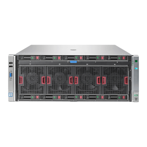
HPE ProLiant DL580 Gen9 Server
User Guide
Abstract
This document is for the person who installs, administers, and troubleshoots servers and storage systems. Hewlett Packard Enterprise
assumes you are qualified in the servicing of computer equipment and trained in recognizing hazards in products with hazardous energy
levels.
Part Number: 799243-002
May 2016
Edition: 3
Advertisement
Table of Contents

Related Manuals for HPE ProLiant DL580 Gen9


Summary of Contents for HPE ProLiant DL580 Gen9
-
Page 1: User Guide
HPE ProLiant DL580 Gen9 Server User Guide Abstract This document is for the person who installs, administers, and troubleshoots servers and storage systems. Hewlett Packard Enterprise assumes you are qualified in the servicing of computer equipment and trained in recognizing hazards in products with hazardous energy levels. - Page 2 © Copyright 2015, 2016 Hewlett Packard Enterprise Development LP The information contained herein is subject to change without notice. The only warranties for Hewlett Packard Enterprise products and services are set forth in the express warranty statements accompanying such products and services. Nothing herein should be construed as constituting an additional warranty.
-
Page 3: Table Of Contents
Contents Component identification .......................... 6 Front panel components ............................6 Front panel LEDs and buttons ..........................7 Systems Insight Display ............................8 Rear panel components ............................9 Power supply LED ..............................10 I/O board components ............................11 System maintenance switch ........................12 NMI jumper .............................. - Page 4 RESTful API support ..........................94 Integrated Management Log ........................95 HPE Insight Remote Support ........................95 HPE ProLiant Pre-boot Health Summary ....................96 HPE Insight Diagnostics ............................96 HPE Insight Diagnostics survey functionality ....................96 Intelligent Provisioning ............................97 Erase Utility ..............................
- Page 5 Mechanical specifications ............................. 112 Power supply specifications ..........................112 HPE 1200 W Common Slot Platinum Plus Hot-Plug Power Supply (94% efficiency) ....... 112 HPE 1500 W Common Slot -48 VDC Hot-plug Power Supply ..............113 HPE 1500 W Common Slot Platinum Plus Hot-Plug Power Supply (94% efficiency) ....... 114 Support and other resources ........................
-
Page 6: Component Identification
Component identification Front panel components Item Description Drive bays 6 to 10* Systems Insight Display Fans 1 to 4 Drive bays 1 to 5 Discovery services connectors Video connector USB connectors (2) * Drives installed in these bays require the optional drive backplane and cables. Component identification 6... -
Page 7: Front Panel Leds And Buttons
Front panel LEDs and buttons Item Description Status Power On/Standby button and • Solid green = System on system power LED • Flashing green (1 Hz/cycle per sec) = Performing power on sequence • Solid amber = System in standby •... -
Page 8: Systems Insight Display
Systems Insight Display The Systems Insight Display LEDs represent the server and component layout. Item Description Power cap • Green = System on or requesting power on • Flashing amber = Power on denied • Off = Standby Overtemperature • Off = Normal •... -
Page 9: Rear Panel Components
Rear panel components Item Description Expansion board slot 1 Expansion board slot 2 Expansion board slot 3 Expansion board slot 4 Expansion board slot 5 Expansion board slot 6 Expansion board slot 7 Expansion board slot 8 Expansion board slot 9 FlexibleLOM slot SPI board Power supply 1... -
Page 10: Power Supply Led
Power supply LED Fail LED-amber Power LED-green Front external health Status (Located on the SID) (Located on the power supply) (Located on the front panel) No AC power to power supply units Green • AC present/Standby outputs on • Power supply DC outputs on and OK Power supply failure •... -
Page 11: I/O Board Components
I/O board components Item Description NMI jumper Slot 1 PCIe3 x16 (16, 8, 4, 2, 1 electrical) Slot 2 PCIe3 x16 (16, 8, 4, 2, 1 electrical) System maintenance switch Slot 3 PCIe3 x16 (16, 8, 4, 2, 1 electrical) Slot 4 PCIe3 x16 (8, 4, 2, 1 electrical) Slot 5 PCIe3 x16 (8, 4, 2, 1 electrical) Slot 6 PCIe3 x16 (16, 8, 4, 2, 1 electrical) -
Page 12: System Maintenance Switch
System maintenance switch The system maintenance switch (SW1) is a twelve-position switch that is used for system configuration. The default position for all twelve positions is Off. Switch Settings • Off = iLO security enabled • On = iLO security disabled •... -
Page 13: Spi Board Components
SPI board components Item Description Top SAS backplane connector SAS cache module connector Systems Insight Display Power/UID connector Internal USB connector TPM connector Front video/USB connector Battery Internal USB connector Serial connector Video connector USB connectors (4) iLO connector FlexibleLOM port 1* FlexibleLOM port 2* FlexibleLOM port 3* FlexibleLOM port 4*... -
Page 14: Power Daughter Board Components
Power daughter board components Item Description Upper SAS backplane power connector I/O board auxiliary power connector I/O board auxiliary power connector I/O board auxiliary power connector I/O board auxiliary power connector I/O board auxiliary power connector I/O board auxiliary power connector Power backplane data connector Power backplane data connector I/O board power connector... -
Page 15: Dimm Slot Locations
DIMM slot locations Each memory cartridge contains 12 DIMM slots. Install DIMMs in pairs in alphabetical order. For installation guidelines, see "Memory options (on page 48)." Component identification 15... -
Page 16: Processors And Memory Cartridges
Processors and memory cartridges The processor memory drawer contains 4 processor sockets and 8 memory cartridges. For DIMM numbering, see "DIMM slot locations (on page 15)." For installation guidelines, see "Memory options (on page 48)." Component identification 16... -
Page 17: Dimm Fault Leds
DIMM fault LEDs Item Description Status Power fault LED (board • Off = The DIMMs are operating normally. • Solid amber = One or more DIMMs in the cartridge is experiencing a power fault condition. General board fault LED • Off = The DIMMs are operating (board B) normally. -
Page 18: Dimm Fault Identification Button
DIMM fault identification button When the DIMM fault LEDs (on page 17) indicate that a DIMM is experiencing an error, press the DIMM fault identification button to illuminate the LED below the affected DIMM ("Memory error LEDs" on page 19). Item Description Board B DIMM fault identification button... -
Page 19: Memory Error Leds
Memory error LEDs When the DIMM fault LEDs (on page 17) indicate that a DIMM is experiencing an error, the memory error LED below the affected DIMM illuminates red when the DIMM fault identification button (on page 18) is pressed. Drive bay numbering Drives installed in bays 6 to 10 require the optional SAS backplane or Express Bay enablement option. -
Page 20: Hot-Plug Drive Led Definitions
Hot-plug drive LED definitions Item Status Definition Locate Solid blue The drive is being identified by a host application. Flashing blue The drive carrier firmware is being updated or requires an update. Activity ring Rotating green Drive activity No drive activity Do not remove Solid white Do not remove the drive. -
Page 21: Fbwc Capacitor Slots
Item Description Release lever Activity ring Do Not Remove button Power button FBWC capacitor slots Item Description Slots 2 to 4—Connect to optional SAS controllers Slot 1—Connects to the SPI board Component identification 21... -
Page 22: Fbwc Module Leds
FBWC module LEDs The FBWC module has three single-color LEDs (one amber and two green). The LEDs are duplicated on the reverse side of the cache module to facilitate status viewing. 1 - Amber 2 - Green 3 - Green Interpretation The cache module is not powered. -
Page 23: Fans
Fans Fan locations Fan guidelines The server has 4 fan modules with 2 rotors in each module. The fan modules operate in a 7+1 configuration. Observe the following guidelines: • If one rotor fails, the system runs with the fans in a degraded condition. •... -
Page 24: Operations
Operations Powering up the server To power up the server, press the Power On/Standby button. Power down the server WARNING: To reduce the risk of personal injury, electric shock, or damage to the equipment, remove the power cord to remove power from the server. The front panel Power On/Standby button does not completely shut off system power. -
Page 25: Extend The Server From The Rack
Extend the server on the rack rails until the server rail-release latches engage. Remove the server from the rack. Extend the server from the rack WARNING: To reduce the risk of personal injury or equipment damage, be sure that the rack is adequately stabilized before extending a component from the rack. -
Page 26: Remove The Access Panel
After performing the installation or maintenance procedure, slide the server into the rack by pressing the server rail-release latches. Remove the access panel WARNING: To reduce the risk of personal injury from hot surfaces, allow the drives and the internal system components to cool before touching them. CAUTION: Do not operate the server for long periods with the access panel open or removed. -
Page 27: Remove The Spi Board
Align the hole in the access panel latch with the guide pin on the chassis. Close the access panel latch. The access panel slides to a closed position. Use a T-15 Torx screwdriver to tighten the access panel latch screw. Remove the SPI board To remove the component: Power down the server (on page 24). -
Page 28: Install The Spi Board
Loosen the thumbscrews on the SPI board, and then lift the SPI board to access the cables. Disconnect all cables from the SPI board. IMPORTANT: If replacing the SPI board or clearing NVRAM, you must re-enter the server serial number through the Advanced System ROM options in UEFI System Utilities ("Re-entering the server serial number and product ID"... - Page 29 Extend the processor memory drawer approximately 2.54 to 5.1 cm (1 to 2 inches). Connect the cables to the SPI board. Operations 29...
-
Page 30: Processor Memory Drawer Shipping Screw Locations
Install the SPI board and tighten the thumbscrews. Install the processor memory drawer ("Remove the processor memory drawer cover" on page 32, on page 31). Install the access panel (on page 26). Install the server into the rack ("Installing the server into the rack"... -
Page 31: Remove The Processor Memory Drawer
Remove the processor memory drawer WARNING: The processor memory drawer weighs more than 11.3 kg (25.0 lb). Use extra caution when removing and replacing the processor memory drawer. Remove the processor memory drawer shipping screws, if installed. Retain the screws for future use ("Processor memory drawer shipping screw locations"... -
Page 32: Remove The Processor Memory Drawer Cover
Install the processor memory drawer. Install the access panel (on page 26). Install the server into the rack ("Installing the server into the rack" on page 38). Connect each power cord to the server. Connect each power cord to the power source. Power up the server ("Powering up the server"... -
Page 33: Access The Systems Insight Display
CAUTION: To prevent damage to electrical components, take the appropriate anti-static precautions before beginning any system installation. Improper grounding can cause electrostatic discharge. To install the component: Remove all power: Disconnect each power cord from the power source. Disconnect each power cord from the server. Do one of the following: Extend the server from the rack (on page 25). - Page 34 After the display fully ejects, rotate the display to the left to view the LEDs. Operations 34...
-
Page 35: Setup
For more information on HPE support services, see the Hewlett Packard Enterprise website (http://www.hpe.com/services). Rack planning resources The rack resource kit ships with all HPE Intelligent Series racks. For more information on the content of each resource, see the rack resource kit documentation. Optimum environment When installing the server in a rack, select a location that meets the environmental standards described in this section. -
Page 36: Temperature Requirements
• Side—The clearance between the installed rack component and the side panels of the rack must be a minimum of 7 cm (2.75 in). IMPORTANT: The HPE ProLiant DL580 Gen9 Server cable management arm is not supported on Compaq branded 7000 series racks. -
Page 37: Electrical Grounding Requirements
WARNING: To reduce the risk of personal injury, fire, or damage to the equipment, do not overload the AC supply branch circuit that provides power to the rack. Consult the electrical authority having jurisdiction over wiring and installation requirements of your facility. CAUTION: Protect the server from power fluctuations and temporary interruptions with a regulating uninterruptible power supply. -
Page 38: Identifying The Contents Of The Server Shipping Carton
Identifying the contents of the server shipping carton Unpack the server shipping carton and locate the materials and documentation necessary for installing the server. All the rack mounting hardware necessary for installing the server into the rack is included with the rack or the server. - Page 39 Install the power cord anchors. Secure the cables to the cable management arm. IMPORTANT: When using cable management arm components, be sure to leave enough slack in each of the cables to prevent damage to the cables when the server is extended from the rack.
-
Page 40: Installing The Operating System
For additional system software and firmware updates, download the Service Pack for ProLiant from the Hewlett Packard Enterprise website (http://www.hpe.com/info/insightcontrol/docs). Software and firmware must be updated before using the server for the first time, unless any installed software or components require an older version. -
Page 41: Register The Product
For more information on automatic configuration, see the UEFI documentation on the Hewlett Packard Enterprise website (http://www.hpe.com/info/ProLiantUEFI/docs). Register the product To experience quicker service and more efficient support, register the product at the Hewlett Packard Enterprise Product Registration website (http://www.hpe.com/info/register). Setup 41... -
Page 42: Hardware Options Installation
Hardware options installation Introduction If more than one option is being installed, read the installation instructions for all the hardware options and identify similar steps to streamline the installation process. WARNING: To reduce the risk of personal injury from hot surfaces, allow the drives and the internal system components to cool before touching them. - Page 43 To install the component: Update the system ROM. Locate and download the latest ROM version from the Hewlett Packard Enterprise Support Center website (http://www.hpe.com/support/hpesc). Follow the instructions on the website to update the system ROM. Power down the server (on page 24).
- Page 44 Firmly holding the processor memory drawer, press the release buttons and then remove the drawer from the server. Remove the processor memory drawer cover. CAUTION: The pins on the processor socket are very fragile. Any damage to them may require replacing the system board. Hardware options installation 44...
- Page 45 Open each of the processor locking levers in the order indicated, and then open the processor retaining bracket. Remove the clear processor socket cover. Retain the processor socket cover for future use. Hardware options installation 45...
- Page 46 Install the processor. Verify that the processor is fully seated in the processor retaining bracket by visually inspecting the processor installation guides on either side of the processor. THE PINS ON THE SYSTEM BOARD ARE VERY FRAGILE AND EASILY DAMAGED. CAUTION: THE PINS ON THE SYSTEM BOARD ARE VERY FRAGILE AND EASILY DAMAGED.
- Page 47 Press and hold the processor retaining bracket in place, and then close each processor locking lever. Press only in the area indicated on the processor retaining bracket. Remove the thermal interface protective cover from the heatsink. CAUTION: To prevent the heatsink from tilting to one side during installation and removal procedures, alternate loosening and tightening the two spring-loaded screws.
-
Page 48: Memory Options
Install the heatsink. Install the processor memory drawer cover. Install the processor memory drawer. Connect each power cord to the server. Connect each power cord to the power source. Power up the server ("Powering up the server" on page 24). Memory options Memory configurations To enhance server availability, the server provides the following AMP modes. -
Page 49: Dimm Identification
DIMM configuration, the server boots in Advanced ECC mode. For more information on the UEFI System Utilities, see the UEFI System Utilities User Guide on the Hewlett Packard Enterprise website (http://www.hpe.com/info/uefi/docs). DIMM identification To determine DIMM characteristics, use the label attached to the DIMM and the following illustration and table. -
Page 50: Dimm Ranks
Memory-processor compatibility information The server processor determines the type of DIMM that will be supported in the server. For the latest memory configuration information, see the product QuickSpecs on the Hewlett Packard Enterprise website (http://www.hpe.com/info/qs). DIMM type • Intel Xeon E7 v3 processors support:... -
Page 51: Dimm Population Guidelines For Memory Modes
The maximum memory capacity is a function of the DIMM capacity, number of installed DIMMs, memory type, and number of installed processors. DIMM DIMM rank Capacity One processor Three processors Four processors type (GB) (GB) Processors (GB) (GB) (GB) Single RDIMM Dual 1152... -
Page 52: Mirrored Memory Population Guidelines
DIMM DIMM rank 1 DIMM 1 DIMM 2 DIMMs 2 DIMMs 3 DIMMs 3 DIMMs type channel channel channel channel channel channel Single (8 GB) 1600 MT/s 1866 MT/s 1600 MT/s 1866 MT/s 1600 MT/s 1600 MT/s RDIMM Dual (16 GB) 1600 MT/s 1866 MT/s 1600 MT/s 1866 MT/s 1333 MT/s... -
Page 53: Installing A Dimm
• For the server to support Mirrored Memory, all processors must have a valid mirroring configuration. • The minimum allowable configuration is two memory cartridges per processor. • Both memory cartridges for each processor must be populated with identical DIMM configurations. •... - Page 54 Press the release button, and then lift the handles on the memory cartridge. Raise the lift tab on the memory cartridge, and then open the cartridge. Open the DIMM slot latches. Hardware options installation 54...
- Page 55 Install the DIMM. CAUTION: When closing the memory cartridge cover, be sure the plastic fingers under the cover do not catch on the top edge of the DIMMs. Close the memory cartridge. While holding the baffle door open, install the memory cartridge. Install the processor memory drawer cover ("Remove the processor memory drawer cover"...
-
Page 56: Memory Cartridge Option
Memory cartridge option Memory cartridge population guidelines When installing memory cartridges, observe the following guidelines: • Memory cartridges installed without a corresponding processor are not utilized: Processor 1 corresponds to memory cartridges 1 and 2. Processor 2 corresponds to memory cartridges 3 and 4. Processor 3 corresponds to memory cartridges 5 and 6. - Page 57 Raise the lift tab on the new memory cartridge, and then open the cartridge. Open the DIMM slot latches. Install the DIMM. CAUTION: When closing the memory cartridge cover, be sure the plastic fingers under the cover do not catch on the top edge of the DIMMs. Close the new memory cartridge.
-
Page 58: Sas Drive Backplane Option
While holding the baffle door open, install the new memory cartridge. Install the processor memory drawer cover ("Remove the processor memory drawer cover" on page 32). Install the processor memory drawer ("Remove the processor memory drawer cover" on page 32, on page 31). - Page 59 Extend the processor memory drawer approximately 2.54 to 5.1 cm (1 to 2 inches). Remove the SPI board. Hardware options installation 59...
- Page 60 Install the backplane, and then tighten the thumbscrews. Be sure the corners of the backplane are aligned under the tabs. Hardware options installation 60...
- Page 61 Connect the data cable. Connect the power cable. Install the SPI board (on page 28). Install the processor memory drawer ("Remove the processor memory drawer cover" on page 32, on page 31). Install the access panel (on page 26). Hardware options installation 61...
-
Page 62: Express Bay Enablement Option
Remove all bezel blanks. Install the drives ("Drive option" on page 72, "Drive option" on page 73). Install blanks in unused drive bays. Connect each power cord to the server. Connect each power cord to the power source. Power up the server ("Powering up the server"... - Page 63 Power down the server (on page 24). Remove all power: Disconnect each power cord from the power source. Disconnect each power cord from the server. Remove the server from the rack (on page 24). Remove the access panel (on page 26). Install the backplane, and then tighten the thumbscrews.
- Page 64 Install the card into an available negotiable link PCI. For slot identification, see "I/O board components (on page 11)." Connect the power and data cables. Item Description Power connection to the system board Data connection to drives 6 and 7 Data connection to drives 8 and 9 Data connection to drive 10 Install the access panel (on page 26).
- Page 65 Remove all bezel blanks. Press the Do Not Remove button to open the release handle. Install the drives. CAUTION: To prevent improper cooling and thermal damage, do not operate the server unless all bays are populated with either a component or a blank. Hardware options installation 65...
-
Page 66: Stand-Up Sas Controller Cable Option
Install the drive blank in any unused drive bays. Connect each power cord to the server. Connect each power cord to the power source. Power up the server ("Powering up the server" on page 24). Stand-up SAS controller cable option The SAS controller cable option is required to enable a PCIe slot-based controller to drive the internal top bay drives. - Page 67 Install the backplane, and then tighten the thumbscrews. Be sure the corners of the backplane are aligned under the tabs. Hardware options installation 67...
- Page 68 Connect the optional SAS controller cable. Connect the power cable. Install the access panel (on page 26). Hardware options installation 68...
-
Page 69: Stand-Up H240 Hba Cable Option
Remove all bezel blanks. Install the drives ("Drive option" on page 72, "Drive option" on page 73). Install blanks in unused drive bays. Connect each power cord to the server. Connect each power cord to the power source. Power up the server ("Powering up the server"... - Page 70 To install the component: Power down the server (on page 24). Remove all power: Disconnect each power cord from the power source. Disconnect each power cord from the server. Remove the server from the rack (on page 24). Remove the access panel (on page 26). Disconnect the existing SAS cable from the SPI board and drive backplane.
-
Page 71: Power Adapter Cables Option
Install the access panel (on page 26). Connect each power cord to the server. Connect each power cord to the power source. Power up the server ("Powering up the server" on page 24). Power adapter cables option WARNING: Do not install these cables in servers that do not specifically identify them in the server documentation. -
Page 72: Drive Option
IMPORTANT: High power PCIe cables report power allocation information used by the server to calculate power supply redundancy rules. For the server to calculate the accurate number of power supplies needed, use the lowest wattage power cable possible for the high- powered PCIe card. -
Page 73: Drive Option
Drive option To install the component: Remove the drive blank. Install the drive. Determine the status of the drive from the hot-plug SAS drive LED combinations ("Hot-plug drive definitions" on page 20). 4U rack bezel option Removing the 4U rack bezel Hardware options installation 73... -
Page 74: Installing The 4U Rack Bezel
Hewlett Packard Enterprise recommends installing redundant hot-plug power supplies in pairs. To confirm the redundancy of your configuration, see the power advisor at the Hewlett Packard Enterprise website (http://www.hpe.com/info/poweradvisor/online). WARNING: To reduce the risk of electric shock or damage to the equipment: •... -
Page 75: Dc Power Supply Option
Remove the power supply blank. Slide the power supply into the power supply bay until the device locks into place. Connect the power cord to the power supply. Connect the power cord to the power source. Be sure that the power supply LED is green. Be sure that the front panel external health LED is green ("Front panel LEDs and buttons"... - Page 76 WARNING: To reduce the risk of electric shock, fire, and damage to the equipment, you must install this product in accordance with the following guidelines: • This power supply is intended only for installation in Hewlett Packard Enterprise servers located in a restricted access location. •...
- Page 77 To install the component: Remove the blank. Remove the ring tongue from the top of the PSU. Hardware options installation 77...
- Page 78 Crimp the ring tongue to the ground cable from the 48 V power source. Remove the black connector from the rear of the PSU. Hardware options installation 78...
- Page 79 Loosen the screws on the connector. Attach the ground (earthed) wire to the ground screw and washer and tighten to 13 lb-in of torque. The ground wire must be connected before connecting the positive or negative lead wires. Hardware options installation 79...
- Page 80 Insert the wires into the connector block and tighten the screws to 10 lb-in of torque. Insert the connector into the PSU. Hardware options installation 80...
-
Page 81: Expansion Board Option
Attach the cables to the power supply handle with the hook-and-loop strap. Insert the power supply into the power supply bay until it clicks into place. Route the power cord. Use best practices when routing power cords and other cables. A cable management arm is available to help with routing. - Page 82 To install the component: Power down the server (on page 24). Remove all power: Disconnect each power cord from the power source. Disconnect each power cord from the server. Extend or remove the server from the rack ("Operations" on page 24). Remove the access panel (on page 26).
-
Page 83: Installing An Expansion Board
Install the expansion board. Close the expansion slot retainer. Connect any required internal or external cables to the expansion board. Install the access panel (on page 26). Install the server in the rack ("Installing the server into the rack" on page 38). Connect each power cord to the server. - Page 84 Open the expansion board retainer, and then remove the expansion slot cover. Remove the PCI retainer screw. Hardware options installation 84...
-
Page 85: Fbwc Module And Capacitor Pack Option
Install the expansion board. Close the expansion slot retainer. Connect any required internal or external cables to the expansion board. Install the access panel (on page 26). Install the server in the rack ("Installing the server into the rack" on page 38). Connect each power cord to the server. - Page 86 Install the cache module. Connect the cable. Install the capacitor pack. Hardware options installation 86...
-
Page 87: Trusted Platform Module Option
Trusted Platform Module option For more information about product features, specifications, options, configurations, and compatibility, see the product QuickSpecs on the Hewlett Packard Enterprise website (http://www.hpe.com/info/qs). Use these instructions to install and enable a TPM on a supported server. This procedure includes three sections: Installing the Trusted Platform Module board (on page 88). -
Page 88: Installing The Trusted Platform Module Board
key/password is required to enter Recovery Mode after BitLocker detects a possible compromise of system integrity. To help ensure maximum security, observe the following guidelines when retaining the recovery key/password: • Always store the recovery key/password in multiple locations. • Always store copies of the recovery key/password away from the server. -
Page 89: Enabling The Trusted Platform Module
For more information on firmware updates and hardware procedures, see the HP Trusted Platform Module Best Practices White Paper on the Hewlett Packard Enterprise Support Center website (http://www.hpe.com/support/hpesc). For more information on adjusting TPM usage in BitLocker, see the Microsoft website (http://technet.microsoft.com/en-us/library/cc732774.aspx). -
Page 90: Cabling
Cabling SPI board cabling Item Description Top SAS backplane connector System Insights Display Power/UID connector Front video/USB connector Cabling 90... -
Page 91: Front Video/Usb Cabling
Front video/USB cabling Systems Insight Display cabling Cabling 91... -
Page 92: Power Supply Data Cabling
Power supply data cabling Standby power cabling Cabling 92... -
Page 93: Software And Configuration Utilities
FWUPDATE utility (on page 103) HPE iLO iLO is a remote server management processor embedded on the system boards of HPE ProLiant and Synergy servers. iLO enables the monitoring and controlling of servers from remote locations. HPE iLO management is a powerful tool that provides multiple ways to configure, update, monitor, and repair servers remotely. -
Page 94: Ilo Restful Api Support
(http://www.hpe.com/info/intelligentprovisioning/docs) iLO RESTful API support HPE iLO 4 firmware version 2.00 and later includes the iLO RESTful API. The iLO RESTful API is a management interface that server management tools can use to perform configuration, inventory, and monitoring of the ProLiant server via iLO. The iLO RESTful API uses basic HTTPS operations (GET, PUT, POST, DELETE, and PATCH) to submit or return JSON-formatted data with iLO web server. -
Page 95: Integrated Management Log
HPE Insight Remote Support Hewlett Packard Enterprise strongly recommends that you register your device for remote support to enable enhanced delivery of your Hewlett Packard Enterprise warranty, HPE support services, or Hewlett Packard Enterprise contractual support agreement. Insight Remote Support supplements your monitoring... -
Page 96: Hpe Proliant Pre-Boot Health Summary
This feature is supported on servers that support external video and have a UID button or an SUV connector. When power is available to the server but the server is not powered on, iLO runs on auxiliary power and can take control of the server video adapter to display the HPE ProLiant Pre-boot Health Summary. -
Page 97: Intelligent Provisioning
(http://www.hpe.com/servers/intelligentprovisioning). For Intelligent Provisioning recovery media downloads, see the Resources tab on the Hewlett Packard Enterprise website (http://www.hpe.com/servers/intelligentprovisioning). For consolidated drive and firmware update packages, see the Smart Update: Server Firmware and Driver Updates page on the Hewlett Packard Enterprise website (http://www.hpe.com/info/SmartUpdate). -
Page 98: Service Pack For Proliant
Launching other pre-boot environments such as the Embedded UEFI Shell and Intelligent Provisioning For more information on the UEFI System Utilities, see the HPE UEFI System Utilities User Guide for HPE ProLiant Gen9 Servers on the Hewlett Packard Enterprise website (http://www.hpe.com/info/uefi/docs). -
Page 99: Using Uefi System Utilities
User Defined Defaults feature in UEFI System Utilities to override the factory default settings. For more information, see the HPE UEFI System Utilities User Guide for HPE ProLiant Gen9 Servers on the Hewlett Packard Enterprise website (http://www.hpe.com/info/uefi/docs). Restoring and customizing configuration settings You can reset all configuration settings to the factory default settings, or you can restore system default configuration settings, which are used instead of the factory default settings. -
Page 100: Secure Boot Configuration
Secure Boot and have an EFI boot loader signed with one of the authorized keys can boot when Secure Boot is enabled. For more information about supported operating systems, see the HPE UEFI System Utilities and Shell Release Notes for HPE ProLiant Gen9 Servers on the Hewlett Packard Enterprise website (http://www.hpe.com/info/uefi/docs). -
Page 101: Ilo Restful Api Support For Uefi
ProLiant Gen8 servers, HPE SSA replaces ACU with an enhanced GUI and additional configuration features. The HPE SSA exists in three interface formats: the HPE SSA GUI, the HPE SSA CLI, and HPE SSA Scripting. Although all formats provide support for configuration tasks, some of the advanced tasks are available in only one format. -
Page 102: Automatic Server Recovery
Automatic Server Recovery ASR is a feature that causes the system to restart when a catastrophic operating system error occurs, such as a blue screen, ABEND, or panic. A system fail-safe timer, the ASR timer, starts when the System Management driver, also known as the Health Driver, is loaded. When the operating system is functioning properly, the system periodically resets the timer. -
Page 103: Keeping The System Current
To download the flash components, see the Hewlett Packard Enterprise Support Center website (http://www.hpe.com/support/hpesc). For more information about the One-Time Boot Menu, see the HPE UEFI System Utilities User Guide for HPE ProLiant Gen9 Servers on the Hewlett Packard Enterprise website (http://www.hpe.com/info/uefi/docs). - Page 104 To obtain the assigned file system volume for the USB key, enter Map –r . For more information about accessing a file system from the shell, see the HPE UEFI Shell User Guide for HPE ProLiant Gen9 Servers on the Hewlett Packard Enterprise website (http://www.hpe.com/info/uefi/docs).
-
Page 105: Drivers
SPP, see the Hewlett Packard Enterprise website (http://www.hpe.com/servers/spp/download). To locate the drivers for a particular server, go to the Hewlett Packard Enterprise Support Center website (http://www.hpe.com/support/hpesc). Under Select your HPE product, enter the product name or number and click Go. -
Page 106: Operating Systems And Virtualization Software Support For Proliant Servers
Hewlett Packard Enterprise offers Change Control and Proactive Notification to notify customers 30 to 60 days in advance of upcoming hardware and software changes on Hewlett Packard Enterprise commercial products. For more information, see the Hewlett Packard Enterprise website (http://www.hpe.com/info/pcn). Software and configuration utilities 106... -
Page 107: Troubleshooting
• Simplified Chinese (http://www.hpe.com/support/Gen9_TSG_zh_cn) The HPE ProLiant Gen9 Troubleshooting Guide, Volume II: Error Messages provides a list of error messages and information to assist with interpreting and resolving error messages on ProLiant servers and server blades. To view the guide, select a language: •... -
Page 108: Battery Replacement
Battery replacement If the server no longer automatically displays the correct date and time, you might need to replace the battery that provides power to the real-time clock. Under normal use, battery life is 5 to 10 years. WARNING: The computer contains an internal lithium manganese dioxide, a vanadium pentoxide, or an alkaline battery pack. - Page 109 To replace the component, reverse the removal procedure. For more information about battery replacement or proper disposal, contact an authorized reseller or an authorized service provider ("Support and other resources" on page 115). Battery replacement 109...
-
Page 110: Warranty And Regulatory Information
Warranty and regulatory information Warranty information HPE ProLiant and x86 Servers and Options (http://www.hpe.com/support/ProLiantServers-Warranties) HPE Enterprise Servers (http://www.hpe.com/support/EnterpriseServers-Warranties) HPE Storage Products (http://www.hpe.com/support/Storage-Warranties) HPE Networking Products (http://www.hpe.com/support/Networking-Warranties) Regulatory information Safety and regulatory compliance For important safety, environmental, and regulatory information, see Safety and Compliance Information for Server, Storage, Power, Networking, and Rack Products, available at the Hewlett Packard Enterprise website (http://www.hpe.com/support/Safety-Compliance-EnterpriseProducts). -
Page 111: Turkey Rohs Material Content Declaration
Local representative information Kazakh: • Russia: • Belarus: • Kazakhstan: Manufacturing date: The manufacturing date is defined by the serial number. CCSYWWZZZZ (serial number format for this product) Valid date formats include: • YWW, where Y indicates the year counting from within each new decade, with 2000 as the starting point;... -
Page 112: Specifications
Depending on installed options, the server is configured with one of the following power supplies: • HPE 1200 W Common Slot Platinum Plus Hot-Plug Power Supply (94% efficiency) (on page 112) • HPE 1500 W Common Slot -48 VDC Hot-plug Power Supply (on page 113) •... -
Page 113: Hpe 1500 W Common Slot -48 Vdc Hot-Plug Power Supply
800 W at 100 VAC input • 900 W at 120 VAC input • 1200 W at 200 V to 240 VAC input HPE 1500 W Common Slot -48 VDC Hot-plug Power Supply Specification Value Input requirements -40 VDC to -72 VDC Rated input voltage Rated input current •... -
Page 114: Hpe 1500 W Common Slot Platinum Plus Hot-Plug Power Supply (94% Efficiency)
(60 V DC). • The branch circuit overcurrent protection must be rated 24 A. HPE 1500 W Common Slot Platinum Plus Hot-Plug Power Supply (94% efficiency) Specification... -
Page 115: Support And Other Resources
Hewlett Packard Enterprise Support Center. You must have an HP Passport set up with relevant entitlements. Websites • Hewlett Packard Enterprise Information Library (http://www.hpe.com/info/enterprise/docs) • Hewlett Packard Enterprise Support Center (http://www.hpe.com/support/hpesc) • Contact Hewlett Packard Enterprise Worldwide (http://www.hpe.com/assistance) -
Page 116: Customer Self Repair
Single Point of Connectivity Knowledge (SPOCK) Storage compatibility matrix (http://www.hpe.com/storage/spock) • Storage white papers and analyst reports (http://www.hpe.com/storage/whitepapers) Customer Self Repair Hewlett Packard Enterprise products are designed with many Customer Self Repair (CSR) parts to minimize repair time and allow for greater flexibility in performing defective parts replacement. If during... - Page 117 Pour plus d'informations sur le programme CSR de Hewlett Packard Enterprise, contactez votre Mainteneur Agrée local. Pour plus d'informations sur ce programme en Amérique du Nord, consultez le site Web Hewlett Packard Enterprise (http://www.hpe.com/support/selfrepair). Riparazione da parte del cliente Per abbreviare i tempi di riparazione e garantire una maggiore flessibilità nella sostituzione di parti difettose, i prodotti Hewlett Packard Enterprise sono realizzati con numerosi componenti che possono essere riparati direttamente dal cliente (CSR, Customer Self Repair).
- Page 118 Weitere Informationen über das Hewlett Packard Enterprise Customer Self Repair Programm erhalten Sie von Ihrem Servicepartner vor Ort. Informationen über das CSR-Programm in Nordamerika finden Sie auf der Hewlett Packard Enterprise Website unter (http://www.hpe.com/support/selfrepair). Reparaciones del propio cliente Los productos de Hewlett Packard Enterprise incluyen muchos componentes que el propio usuario puede reemplazar (Customer Self Repair, CSR) para minimizar el tiempo de reparación y ofrecer una mayor...
- Page 119 Packard Enterprise, póngase en contacto con su proveedor de servicios local. Si está interesado en el programa para Norteamérica, visite la página web de Hewlett Packard Enterprise CSR (http://www.hpe.com/support/selfrepair). Customer Self Repair Veel onderdelen in Hewlett Packard Enterprise producten zijn door de klant zelf te repareren, waardoor de reparatieduur tot een minimum beperkt kan blijven en de flexibiliteit in het vervangen van defecte onderdelen groter is.
- Page 120 Para obter mais informações sobre o programa de reparo feito pelo cliente da Hewlett Packard Enterprise, entre em contato com o fornecedor de serviços local. Para o programa norte-americano, visite o site da Hewlett Packard Enterprise (http://www.hpe.com/support/selfrepair). Support and other resources 120...
- Page 121 Support and other resources 121...
- Page 122 Support and other resources 122...
-
Page 123: Remote Support
Hewlett Packard Enterprise, which will initiate a fast and accurate resolution based on your product’s service level. Hewlett Packard Enterprise strongly recommends that you register your device for remote support. For more information and device support details, go to the Insight Remote Support website (http://www.hpe.com/info/insightremotesupport/docs). Support and other resources 123... -
Page 124: Documentation Feedback
Hewlett Packard Enterprise is committed to providing documentation that meets your needs. To help us improve the documentation, send any errors, suggestions, or comments to Documentation Feedback (mailto:docsfeedback@hpe.com). When submitting your feedback, include the document title, part number, edition, and publication date located on the front cover of the document. For online help content, include the product name, product version, help edition, and publication date located on the legal notices page. -
Page 125: Acronyms And Abbreviations
Automatic Server Recovery BBWC battery-backed write cache Canadian Standards Association DDDC Double Device Data Correction electrostatic discharge FBWC flash-backed write cache HPE SSA HPE Smart Storage Administrator International Electrotechnical Commission iLO 4 Integrated Lights-Out 4 Integrated Management Log Acronyms and abbreviations 125... - Page 126 keyboard, video, and mouse NVRAM nonvolatile memory ORCA Option ROM Configuration for Arrays PCIe Peripheral Component Interconnect Express PCI-X peripheral component interconnect extended power distribution unit port ID POST Power-On Self Test QuickPath Interconnect Reliability, Availability, Serviceability RBSU ROM-Based Setup Utility serial attached SCSI Secure Digital SDDC...
- Page 127 Systems Insight Manager Scalable memory interfaces system peripheral interface Service Pack for ProLiant TMRA recommended ambient operating temperature Trusted Platform Module UEFI Unified Extensible Firmware Interface unit identification uninterruptible power system universal serial bus Version Control Agent Acronyms and abbreviations 127...
-
Page 128: Index
Index diagnostic tools 93, 96, 99, 100, 102 diagnostics utility 96 DIMM banks, identification 49 access panel 26 DIMM fault identification button 18 ACU (Array Configuration Utility) 101 DIMM fault LEDs 17 airflow requirements 35, 36 DIMM identification 49 ASR (Automatic Server Recovery) 102 DIMM slot locations 15 authorized reseller 115 DIMMs 49, 50, 51, 53... - Page 129 102 help resources 115 online spare memory 48, 52 Hewlett Packard Enterprise website 115 operating systems 105, 106 HPE UEFI System Utilities 98, 99 operating systems supported 96, 105, 106 operations 24 optimum environment 35 options installation 38, 42...
- Page 130 regulatory compliance notices 110, 111 UPS (uninterruptible power supply) 36 remote support and analysis tools 95 USB support 102 remove server from rack 24 utilities 93, 98, 99, 101 removing the processor memory drawer 31 utilities, deployment 93, 97 requirements, electrical grounding 37 requirements, environmental 35, 112 requirements, power 36 ventilation 35...
Need help?
Do you have a question about the ProLiant DL580 Gen9 and is the answer not in the manual?
Questions and answers