
Related Manuals for BODYMAX B200


Summary of Contents for BODYMAX B200
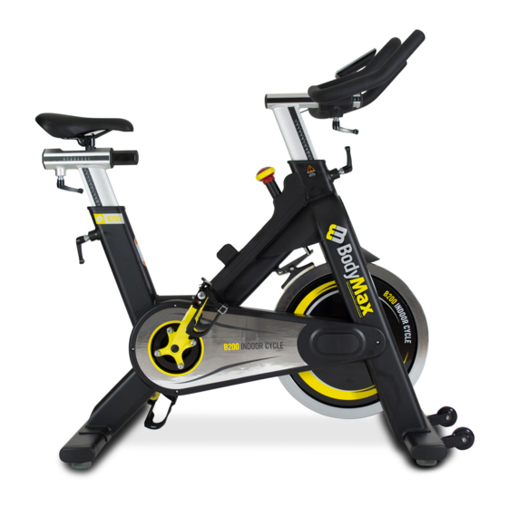
- Page 1 B200 OWNER'S MANUAL BODYMAX FITNESS 57 BEARDMORE WAY,CLYDEBANK G81 4HT www.bodymaxfitness.com...
- Page 2 This is especially important for individuals over the age of 35 or persons with pre-existing health problems. BODYMAX B200 at all times. adjust beyond the marked If unsure about the correct use for the Bodymax B200, please contact the store where you purchased the cycle.
- Page 3 EXPLODED 1 EXPLORE VIEW...
- Page 4 EXPLODED 2...
- Page 5 BODYMAX B200 Parts List Main Frame Rear Stabilizer Rear Stabilizer fixed bolts Front Stabilizer fixed bolts plastic sleeve . Plastic end cap Washer Front Stabilizer Fly Wheels Fixed Nut Washer bolts Handlebar Lock lever for HB and seat Saddle clamp...
- Page 6 BODYMAX B200 Parts List Brake pad Brake pad fixed screw Bush Brake Arm Spacer Lift spring Washer Stud B Brake arms fixed Bolt Washer Stud A Transportation wheel Front Stabilizer End Cap Bearing 608ZZ Bolt Axle Lock Nut Dusty Cover Spacer B.B Axle...
- Page 7 STEP 1 FRONT AND REAR STABILIZER 1. Attach the Front Stabilizer ( 7 ) to the Main Frame (1) on a flat level surface floor , using two M8 Dome Bolts ( 3A ) , two M8 Washers (6). 2. Attach the Rear Stabilizer (2) to the Main Frame (1) , using two M8 X 4"...
- Page 8 STEP 2 PEDALS ASSEMBLY 1. Carefully align the thread of the axle on the Right Pedal ( 70R) ( "R" marked on the end of pedal axle ). With threaded hole on the right crank arm and screw in clockwise by HAND. Tighten the pedal to the crank arm using a 15mm wrench.
- Page 9 STEP 3 ASSEMBLE HANDLEBAR AND STEM 1. Insert the Handlebar Stem (20) into the Front tube of the Main Frame (1) . You will be able to adjust the height of the Handlebar Stem and then using the pre-installed Locking Lever (18). If you do not have room to turn the handle on the locking lever .
- Page 10 STEP 4 SADDLE AND SEAT POST ASSEMBLY 1. Insert the Seat Post (15) into the rear tube on the Main Frame (1) . You will be able to adjust the height of the seat post and then tighten using the pre-installed Locking Lever (18). If you do not have room to turn the handle on the Locking Lever.
- Page 11 Assembly is complete! Please take the following steps before using the BODYMAX B200 INDOOR TRAINING CYCLE: 1. Make certain all bolts are tightened securely. 2. Seat Post (15) and Handlebar Stem (20) are adjusted to your personal desired height and locked with the Lock Lever (18). Note: You can pull the LockLever to position the lever away from the frame if needed.
Need help?
Do you have a question about the B200 and is the answer not in the manual?
Questions and answers