Vega VEGAPULS 67 Operating Instructions Manual
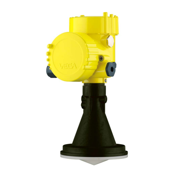
Radar sensor for continuous level measurement of bulk solids
Hide thumbs
Also See for VEGAPULS 67:
- Operating instructions manual (96 pages) ,
- Quick setup manual (24 pages) ,
- Product information (20 pages)

Related Manuals for Vega VEGAPULS 67


Summary of Contents for Vega VEGAPULS 67
-
Page 1: Operating Instructions
Operating Instructions Radar sensor for continuous level measurement of bulk solids VEGAPULS 67 4 … 20 mA/HART - four-wire Document ID: 36532... -
Page 2: Table Of Contents
Saving the parameter adjustment data ................56 Set up with other systems DD adjustment programs ....................57 Field Communicator 375, 475 ..................57 Diagnosis, asset management and service Maintenance ........................58 VEGAPULS 67 • 4 … 20 mA/HART - four-wire... - Page 3 11.2 Dimensions ........................75 Safety instructions for Ex areas Take note of the Ex specific safety instructions for Ex applications. These instructions are attached as documents to each instrument with Ex approval and are part of the operating instructions manual. Editing status: 2016-01-29 VEGAPULS 67 • 4 … 20 mA/HART - four-wire...
-
Page 4: About This Document
This arrow indicates a single action. Sequence of actions Numbers set in front indicate successive steps in a procedure. Battery disposal This symbol indicates special information about the disposal of bat- teries and accumulators. VEGAPULS 67 • 4 … 20 mA/HART - four-wire... -
Page 5: For Your Safety
During work on and with the device the required personal protective equipment must always be worn. Appropriate use VEGAPULS 67 is a sensor for continuous level measurement. You can find detailed information about the area of application in chapter "Product description". Operational reliability is ensured only if the instrument is properly used according to the specifications in the operating instructions manual as well as possible supplementary instructions. -
Page 6: Ce Conformity
(e.g. electrically conductive coating) • Manholes and flanges on the vessel must be closed and sealed to avoid penetration of the radar signal • The instrument should be preferably mounted on top of the vessel with antenna orientation downward VEGAPULS 67 • 4 … 20 mA/HART - four-wire... -
Page 7: Radio License For Usa/Canada
That is why we have introduced an environment management system with the goal of continuously improving company environmental pro- tection. The environment management system is certified according to DIN EN ISO 14001. Please help us fulfill this obligation by observing the environmental instructions in this manual: • Chapter "Packaging, transport and storage" • Chapter "Disposal" VEGAPULS 67 • 4 … 20 mA/HART - four-wire... -
Page 8: Product Description
Alternatively, you can access the data via your smartphone: • Download the smartphone app "VEGA Tools" from the "Apple App Store" or the "Google Play Store" • Scan the Data Matrix code on the type label of the instrument or •... -
Page 9: Principle Of Operation
Principle of operation Application area The VEGAPULS 67 is a radar sensor for continuous level measure- ment of bulk solids under simple process conditions. It is suitable for smaller silos and vessels. The instrument is also suitable for applications in liquids. -
Page 10: Accessories And Replacement Parts
PACTware with VEGA-DTM is required. You can find further information in the operating instructions "Interface adapter VEGACONNECT" (Document-ID 32628). VEGADIS 81 The VEGADIS 81 is an external display and adjustment unit for VEGA plics sensors. ® For sensors with double chamber housing the interface adapter "DISADAPT"... - Page 11 4 … 20 mA/HART - two-wire: four-wire • VEGAPULS series 60 • VEGAFLEX 80 series • VEGABAR series 80 You can find further information in the operating instructions "Supple- mentary electronics for 4 … 20 mA/HART - four-wire" (Document-ID 42766). VEGAPULS 67 • 4 … 20 mA/HART - four-wire...
-
Page 12: Mounting
The free openings for the cable glands are therefore covered with red dust protection caps as transport protection. The dust protection caps do not provide sufficient protection against moisture. VEGAPULS 67 • 4 … 20 mA/HART - four-wire... -
Page 13: Collar Or Adapter Flange
Mounting strap The mounting strap enables simple mounting on the vessel wall or silo top. It is suitable for wall, ceiling or boom mounting. Especially in open vessels this is a very easy and effective way to align the sensor to the bulk solid surface. VEGAPULS 67 • 4 … 20 mA/HART - four-wire... - Page 14 – Angle of inclination in three steps 0°, 90° and 180° • Double chamber housing – Angle of inclination 90°, infinitely variable – Angle of inclination in two steps 0° and 90° Fig. 4: Adjustment of the angle of inclination VEGAPULS 67 • 4 … 20 mA/HART - four-wire...
-
Page 15: Mounting Instructions
Marking bar Installation position Mount the instrument at least 200 mm (7.874 in) away from the vessel wall. 200 mm (7.87") Fig. 7: Mounting the radar sensor on the vessel top VEGAPULS 67 • 4 … 20 mA/HART - four-wire... - Page 16 The optimum mounting position is on the opposite of the filling. To avoid strong pollution, the distance to the filter or dust extraction must be as big as possible. Fig. 8: Mounting of the radar sensor with inflowing medium - filling from top Lateral filling: With bulk solids silos with lateral pneumatic filling, mounting should not be in the filling stream as the microwave signal will be interferred. The optimum mounting position is next to the filling. To avoid strong pollution, the distance to the filter or dust extraction must be as big as possible. VEGAPULS 67 • 4 … 20 mA/HART - four-wire...
- Page 17 With the aluminium double chamber housing, retroactive mount- ing in this way is not possible - the mounting type must be specified with the order. Information: The mounting socket should be as short as possible and its end rounded. This reduces false echoes from the vessel mounting socket. VEGAPULS 67 • 4 … 20 mA/HART - four-wire...
- Page 18 Tip: In new facilities it is useful to incline the vessel socket in the direction of the outlet. False reflections from the vessel wall are thus reduced and measurement all the way down to the bottom of the conical outlet is possible. VEGAPULS 67 • 4 … 20 mA/HART - four-wire...
- Page 19 To detect nearly the complete vessel volume the sensor should be directed in such a way that the measuring beam reaches the lowest level in the vessel, i.e. the outlet. Fig. 13: Mounting in open vessel VEGAPULS 67 • 4 … 20 mA/HART - four-wire...
- Page 20 Large material heaps are best measured with several instruments, which can be mounted on e.g. traverse cranes. For this type of ap- plication it is advantageous to orient the sensor perpendicular to the bulk solid surface. VEGAPULS 67 • 4 … 20 mA/HART - four-wire...
- Page 21 Fig. 17: Cover flat, large-area profiles with deflectors Agitators If there are agitators in the vessel, a false signal suppression should be carried out with the agitators in motion. This ensures that the interfering reflections from the agitators are saved with the blades in different positions. VEGAPULS 67 • 4 … 20 mA/HART - four-wire...
- Page 22 The optimum mounting position is on the outer wall of the silo with the sensor oriented towards the outlet in the silo center. VEGAPULS 67 • 4 … 20 mA/HART - four-wire...
- Page 23 Air rinsing Air rinsing is useful for avoiding buildup, particularly when there is strong condensation. Since VEGAPULS 67 has no direct rinsing air connection, a separate rinsing air connection must be provided in the mounting socket. By inclining this connection towards the top, a particularly effective cleaning of the antenna cover is achieved.
- Page 24 4 Mounting Fig. 22: Purging air connection VEGAPULS 67 • 4 … 20 mA/HART - four-wire...
-
Page 25: Connecting To Power Supply
In the case of instrument housings with metric thread, the cable glands are screwed in at the factory. They are sealed with plastic plugs as transport protection. You have to remove these plugs before electrical connection. VEGAPULS 67 • 4 … 20 mA/HART - four-wire... - Page 26 (low impedance). In Ex systems, the grounding is carried out according to the installa- tion regulations. VEGAPULS 67 • 4 … 20 mA/HART - four-wire...
-
Page 27: Connection
When the screwdriver is released, the terminal closes again. 6. Check the hold of the wires in the terminals by lightly pulling on them VEGAPULS 67 • 4 … 20 mA/HART - four-wire... -
Page 28: Wiring Plan, Double Chamber Housing
Internal connection to the terminal compartment For display and adjustment module or interface adapter Information: The connection of an external display and adjustment unit is not pos- sible with the Ex-d-ia version. VEGAPULS 67 • 4 … 20 mA/HART - four-wire... - Page 29 Fig. 26: Connection compartment with double chamber housing with low volt- Terminal Function Polarity Voltage supply Voltage supply 4 … 20 mA output (active) 4 … 20 mA output (passive) Mass - output VEGAPULS 67 • 4 … 20 mA/HART - four-wire...
-
Page 30: Double Chamber Housing With Disadapt
Pin 1 Pin 2 Pin 3 Pin 4 Contact pin Colour connection ca- Terminal, electronics ble in the sensor module Pin 1 Brown Pin 2 White Pin 3 Blue Pin 4 Black VEGAPULS 67 • 4 … 20 mA/HART - four-wire... -
Page 31: Switch-On Phase
As soon as a plausible measured value is found, the corresponding current is outputted to the signal cable. The value corresponds to the actual level as well as the settings already carried out, e.g. factory setting. VEGAPULS 67 • 4 … 20 mA/HART - four-wire... -
Page 32: Set Up With The Display And Adjustment Module
The display and adjustment module is powered by the sensor, an ad- ditional connection is not necessary. Fig. 29: Installing the display and adjustment module in the electronics compart- ment of the single chamber housing VEGAPULS 67 • 4 … 20 mA/HART - four-wire... -
Page 33: Adjustment System
Adjustment system Fig. 31: Display and adjustment elements LC display Adjustment keys • Key functions [OK] key: VEGAPULS 67 • 4 … 20 mA/HART - four-wire... -
Page 34: Measured Value Indication - Selection National Language
During the initial setup of an instrument shipped Ex works, use the "OK" key to get to the menu "National language". VEGAPULS 67 • 4 … 20 mA/HART - four-wire... -
Page 35: Parameter Adjustment
You can enter an unambiguous designation for the sensor, e.g. the measurement loop name or the tank or product designation. In digital systems and in the documentation of larger plants, a singular desig- VEGAPULS 67 • 4 … 20 mA/HART - four-wire... - Page 36 With this menu item, the sensor can be adapted to the applications. The adjustment possibilities depend on the selection "Liquid" or "Bulk solid" under "Medium". The following options are available when "Liquid" is selected: VEGAPULS 67 • 4 … 20 mA/HART - four-wire...
- Page 37 – Condensation, buildup by movement – Max. requirement on measurement accuracy from 95 % • Properties, sensor: – Low sensitivity to sporadic false echoes – Stable and reliable measured values through averaging VEGAPULS 67 • 4 … 20 mA/HART - four-wire...
- Page 38 – Entering the tube inside diameter takes the running time shift into consideration – Echo detection sensitivity reduced Bypass: • Product speed: – Fast up to slow filling with short up to long bypass tube possible – Often the level is hold via a control facility VEGAPULS 67 • 4 … 20 mA/HART - four-wire...
- Page 39 – Spiders and insects build nests in the antennas – Floating material and animals sporadically appear on water surface • Properties, sensor: – Stable and reliable measured values through frequent averag- VEGAPULS 67 • 4 … 20 mA/HART - four-wire...
- Page 40 Apart from the medium and the application, the vessel form itself can Setup - Vessel form influence the measurement. To adapt the sensor to these measuring conditions, this menu item offers different options for vessel bottom and ceiling for certain applications. VEGAPULS 67 • 4 … 20 mA/HART - four-wire...
- Page 41 To perform the adjustment, enter the distance with full and empty ves- sel, see the following example: 100% Fig. 32: Parameter adjustment example min./max. adjustment Min. level = max. measuring distance Max. level = min. measuring distance VEGAPULS 67 • 4 … 20 mA/HART - four-wire...
- Page 42 Setup - Max. adjustment Proceed as follows: 1. Select with [->] the menu item Max. adjustment and confirm with [OK]. 2. Prepare the percentage value for editing with [OK] and set the cursor to the requested position with [->]. VEGAPULS 67 • 4 … 20 mA/HART - four-wire...
- Page 43 The default setting is output characteristics 4 … 20 mA, failure mode < 3.6 mA. Setup - Current output In the menu item "Current output Min./Max.", you determine the reac- Min./Max. tion of the current output during operation. VEGAPULS 67 • 4 … 20 mA/HART - four-wire...
- Page 44 This menu item enables the setting of the requested national lan- Display - Language guage. In the delivery status, the sensor is set to the ordered national lan- guage. Display - Displayed value In this menu item you can define the indication of the measured value on the display. VEGAPULS 67 • 4 … 20 mA/HART - four-wire...
- Page 45 The measurement reliability equals signal strength minus noise. The higher the value, the more reliable the measurement. With a function- ing measurement, the values are > 10 dB. VEGAPULS 67 • 4 … 20 mA/HART - four-wire...
- Page 46 "Additional settings") of the empty vessel with signal strength in "dB" over the measuring range. A comparison of echo curve and false signal suppression allows a more detailed statement of the reliability. VEGAPULS 67 • 4 … 20 mA/HART - four-wire...
- Page 47 This should be done with a low level so that all potential interfering reflections can be detected. Proceed as follows: 1. Select with [->] the menu item "False signal suppression" and confirm with [OK]. VEGAPULS 67 • 4 … 20 mA/HART - four-wire...
- Page 48 A linearization is necessary for all vessels in which the vessel volume Additional adjustments - Linearization curve does not increase linearly with the level - e.g. a horizontal cylindri- cal or spherical tank - and the indication or output of the volume is required. Corresponding linearization curves are preprogrammed VEGAPULS 67 • 4 … 20 mA/HART - four-wire...
- Page 49 In this menu item, the internal clock of the sensor is adjusted. Date/Time Additional adjustments With a reset, certain parameter adjustments carried out by the user - Reset are reset. The following reset functions are available: VEGAPULS 67 • 4 … 20 mA/HART - four-wire...
- Page 50 Max. adjustment 0,000 m(d) Damping 0.0 s Current output 4 … 20 mA, < 3.6 mA mode Current output Min. current 3.8 mA, max. current Min./Max. 20.5 mA Lock adjustment Released VEGAPULS 67 • 4 … 20 mA/HART - four-wire...
- Page 51 In the menu "Additional settings" the items "Distance unit, tem- perature unit and linearization" • The values of the user programmable linearization curve The 4 … 20 mA signal of the HART sensor is switched off. The sensor consumes a constant current of 4 mA. The measuring signal is transmitted exclusively as digital HART signal. VEGAPULS 67 • 4 … 20 mA/HART - four-wire...
- Page 52 PC. Instrument features In this menu item, the features of the sensor such as approval, pro- cess fitting, seal, measuring range, electronics, housing and others are displayed. VEGAPULS 67 • 4 … 20 mA/HART - four-wire...
-
Page 53: Saving The Parameter Adjustment Data
If it is necessary to exchange a sensor, the display and adjustment module is inserted into the replacement instrument and the data are likewise written into the sensor via the menu item "Copy sensor data". VEGAPULS 67 • 4 … 20 mA/HART - four-wire... -
Page 54: Setup With Pactware
4 … 20 mA signal output HART resistance approx. 250 Ω (optional depending on processing) Connection cable with 2 mm pins and terminals VEGACONNECT Processing system/PLC Necessary components: • VEGAPULS 67 VEGAPULS 67 • 4 … 20 mA/HART - four-wire... -
Page 55: Parameter Adjustment
"DTM Collection/PACTware" attached to each DTM Collection and which can also be downloaded from the Internet. Detailed descrip- tions are available in the online help of PACTware and the DTMs. VEGAPULS 67 • 4 … 20 mA/HART - four-wire... -
Page 56: Saving The Parameter Adjustment Data
CD from the agency serving you. Saving the parameter adjustment data We recommend documenting or saving the parameter adjustment data via PACTware. That way the data are available for multiple use or service purposes. VEGAPULS 67 • 4 … 20 mA/HART - four-wire... -
Page 57: Set Up With Other Systems
This software is updated via the Internet and new EDDs are automatically taken over into the device catalogue of this software after they are released by the manufacturer. They can then be transferred to a Field Communicator. VEGAPULS 67 • 4 … 20 mA/HART - four-wire... -
Page 58: Diagnosis, Asset Management And Service
Echo curve of the setup: This is used as reference echo curve for the measurement conditions during setup. Changes in the measure- ment conditions during operation or buildup on the sensor can thus be recognized. The echo curve of the setup is stored via: VEGAPULS 67 • 4 … 20 mA/HART - four-wire... -
Page 59: Asset Management Function
PACTware/DTM or EDD. Out of specification: The measured value is unstable because the instrument specification is exceeded (e.g. electronics temperature). This status message is inactive by default. It can be activated by the user via PACTware/DTM or EDD. Maintenance: Due to external influences, the instrument function is limited. The measurement is affected, but the measured value is VEGAPULS 67 • 4 … 20 mA/HART - four-wire... - Page 60 – EMC interference – Remove EMC influences Bit 12 of Byte 0…5 – Transmission error with – Exchange 4-wire power Communication error the external communica- supply unit or electron- tion with 4-wire power supply unit VEGAPULS 67 • 4 … 20 mA/HART - four-wire...
- Page 61 – Temperature of the – Check ambient tem- Bit 5 of Byte 14…24 electronics in the non- perature Impermissible electronics specified range – Isolate electronics temperature – Use instrument with higher temperature range VEGAPULS 67 • 4 … 20 mA/HART - four-wire...
-
Page 62: Rectify Faults
The operator of the system is responsible for taking suitable meas- tion occurs ures to rectify faults. Procedure for fault recti- The first measures are: fication • Evaluation of fault messages, for example via the display and adjustment module VEGAPULS 67 • 4 … 20 mA/HART - four-wire... - Page 63 "Hold value" • If the level indication is too low, the reason could be a line resist- ance that is too high VEGAPULS 67 • 4 … 20 mA/HART - four-wire...
- Page 64 100 % during filling signal suppression with con- densation/contamination in the close range by editing time – With bulk solids use radar sen- sor with purging air connection or flexible antenna cover VEGAPULS 67 • 4 … 20 mA/HART - four-wire...
-
Page 65: Exchanging The Electronics Module
24 hour service hotline Should these measures not be successful, please call in urgent cases the VEGA service hotline under the phone no. +49 1805 858550. The hotline is also available outside normal working hours, seven days a week around the clock. -
Page 66: Software Update
If a repair is necessary, please proceed as follows: • Print and fill out one form per instrument • Clean the instrument and pack it damage-proof • Attach the completed form and, if need be, also a safety data sheet outside on the packaging VEGAPULS 67 • 4 … 20 mA/HART - four-wire... - Page 67 9 Diagnosis, asset management and service • Please contact the agency serving you to get the address for the return shipment. You can find the agency on our home page www.vega.com. VEGAPULS 67 • 4 … 20 mA/HART - four-wire...
-
Page 68: Dismount
Pass the instrument directly on to a spe- cialised recycling company and do not use the municipal collecting points. These may be used only for privately used products according to the WEEE directive. VEGAPULS 67 • 4 … 20 mA/HART - four-wire... -
Page 69: Supplement
Ʋ Flange screws, adapter flange DN 100 7 Nm (5.163 lbf ft) Max. torque for NPT cable glands and Conduit tubes Ʋ Plastic housing 10 Nm (7.376 lbf ft) Ʋ Aluminium/Stainless steel housing 50 Nm (36.88 lbf ft) VEGAPULS 67 • 4 … 20 mA/HART - four-wire... - Page 70 Fig. 46: Data of the input variable Reference plane Measured variable, max. measuring range Antenna length Utilisable measuring range Max. measuring range 15 m (49.21 ft) Recommended measuring range up to 15 m (49.21 ft) VEGAPULS 67 • 4 … 20 mA/HART - four-wire...
- Page 71 Ʋ Min. distance to internal installations > 200 mm (7.874 in) Ʋ Reflector Flat plate reflector Ʋ False reflections Biggest false signal, 20 dB smaller than the useful signal Deviation with liquids See following diagrams VEGAPULS 67 • 4 … 20 mA/HART - four-wire...
- Page 72 Ʋ Average spectral transmission power -14 dBm/MHz EIRP density Time span after a sudden measuring distance change by max. 0.5 m in liquid applications, max 2 m with bulk solids applications, until the output signal has taken for the first time 90 % of the final value (IEC 61298-2). Outside the specified beam angle, the energy level of the radar signal is 50% (-3 dB) less. EIRP: Equivalent Isotropic Radiated Power. VEGAPULS 67 • 4 … 20 mA/HART - four-wire...
- Page 73 IP 20 Ʋ mounted in the housing without lid IP 40 Materials Ʋ Housing Ʋ Inspection window Polyester foil Interface to the external display and adjustment unit Data transmission Digital (I²C-Bus) VEGAPULS 67 • 4 … 20 mA/HART - four-wire...
- Page 74 Ʋ up to 5000 m (16404 ft) above sea III - Only with connected overvoltage protection level Ʋ up to 5000 m (16404 ft) above sea level Degree of soiling Protection rating (IEC 61010-1) VEGAPULS 67 • 4 … 20 mA/HART - four-wire...
-
Page 75: Dimensions
Instruments with approvals can have different technical specifications depending on the version. For that reason the associated approval documents of these instruments have to be carefully noted. They are part of the delivery or can be downloaded under www.vega.com, "VEGA Tools" and "Instrument search" as well as in the download area. - Page 76 VEGAPULS 67, version with mounting strap 125 mm (4.92") 2,5 mm (0.10") 1.4301 PBT-GF30 75 mm (2.95") 9 mm 107 mm (0.35") (4.21") 115 mm (4.53") 12 mm (0.47") Fig. 49: VEGAPULS 67, with mounting strap VEGAPULS 67 • 4 … 20 mA/HART - four-wire...
- Page 77 ø 75 mm (2.95") ø 115 mm (4.53") ø 156 mm (6.14") ø 200 mm (7.87") Fig. 50: VEGAPULS 67, compression flange suitable for DN 80 PN 16/ASME 3" 150lbs/JIS80 10K VEGAPULS 67 • 4 … 20 mA/HART - four-wire...
- Page 78 11 Supplement VEGAPULS 67, version with adapter flange ø 75 mm (2.95") ø 98 mm (3.86") Fig. 51: VEGAPULS 67, adapter flange Adapter flange Seal VEGAPULS 67 • 4 … 20 mA/HART - four-wire...
- Page 79 Les lignes de produits VEGA sont globalement protégées par des droits de propriété intellec- tuelle. Pour plus d'informations, on pourra se référer au site www.vega.com. VEGA lineas de productos están protegidas por los derechos en el campo de la propiedad indus- trial. Para mayor información revise la pagina web www.vega.com.
- Page 80 Functional principle 9 Terminal compartment – Double chamber housing 29 Grounding 26 Vessel form 40 Vessel height 41 HART mode 51 Vessel installations 21 Voltage supply 25, 74 Instrument version 52 Language 44 VEGAPULS 67 • 4 … 20 mA/HART - four-wire...
- Page 81 Notes VEGAPULS 67 • 4 … 20 mA/HART - four-wire...
- Page 82 Notes VEGAPULS 67 • 4 … 20 mA/HART - four-wire...
- Page 83 Notes VEGAPULS 67 • 4 … 20 mA/HART - four-wire...
- Page 84 Subject to change without prior notice © VEGA Grieshaber KG, Schiltach/Germany 2016 VEGA Grieshaber KG Phone +49 7836 50-0 Am Hohenstein 113...
Need help?
Do you have a question about the VEGAPULS 67 and is the answer not in the manual?
Questions and answers