Rotel RB-991 Technical Manual
Hide thumbs
Also See for RB-991:
- Owner's manual (22 pages) ,
- Owner's manual (8 pages) ,
- Owner's manual (8 pages)
Advertisement
Table of Contents
Quality Uncompromised
T echnical
Manual
Table of Contents
Specification.....................................1
Wiring Diagram ................................2
Parts List ..........................................3,4
Adjustment.......................................4
Pcb Assembly .................................5,6
Schematic Diagram..........................7,8
Specification
(20-20 kHz, ≤ 0.03%, 8 ohms)
Continuous Power Output
(20-20 kHz, ≤ 0.05%, 4 ohms)
Total Harmonic Distortion
(20 Hz-20 kHz, 8 ohms)
Intermodulation Distortion
(60 Hz: 7 kHz, 4:1)
Frequency Response
Damping Factor
(20-20,000 Hz, 8 ohms)
Speaker Impedance
Signal to Noise Ratio
(IHF A network)
Input Impedance/Sensitivity
(RCA Inputs)
(XLR Inputs)
Power Requirements
Power Consumption
Dimensions
(W, H, D)
Weight (net)
BUNZAN-SHINSEN-BLD. 4F 10-10 SHINSEN-CHO, SHIBUYA-KU,
TOKYO 150-0045, JAPAN
®
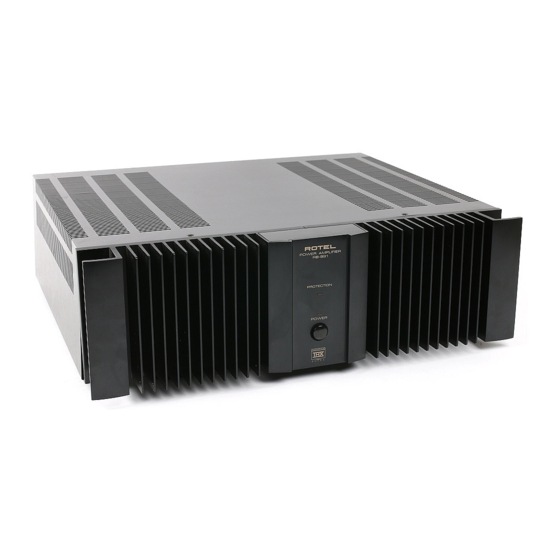
STEREO POWER AMPLIFIER
RB-991
200 watts/ch.
300 watts/ch.
≤ 0.03%
≤ 0.03%
≥ 10-100,000 Hz, ± 1 dB
≥ 500
4-16 ohms
120 dB
33 k Ohms/1.0 volt
33k Ohms/1.0 volt
115 Volts, 60 Hz or
230 Volts, 50 Hz
550 Watts
440 x 127 x 385 mm
17.38 x 4.76 x 15.16"
16.7 kg., 36.74 lb.
Serial. NO.
Begining
Y-310A-98061M/S-S
Wiring Diagram
2
Advertisement
Table of Contents

Related Manuals for Rotel RB-991


Summary of Contents for Rotel RB-991
- Page 1 Wiring Diagram Quality Uncompromised ® T echnical STEREO POWER AMPLIFIER RB-991 Manual Table of Contents Specification........1 Wiring Diagram ........2 Parts List ..........3,4 Adjustment........4 PCB Assembly .........5,6 Schematic Diagram......7,8 Specification (20-20 kHz, ≤ 0.03%, 8 ohms) Continuous Power Output 200 watts/ch.
- Page 2 Parts List Parts List SYMBOL PARTS NO. DESCRIPTION SYMBOL PARTS NO. DESCRIPTION SYMBOL PARTS NO. DESCRIPTION SYMBOL PARTS NO. DESCRIPTION X-1177-01,02 PCB ASSEMBLY X-1237-01 PCB ASSEMBLY HEAT SINKER ASSEMBLY C601,602 041 50BGF4R7M CAP,ELEC.50V4.7UF C001 044 DE7150F472M SPARK KILLER Q617,618 032 L2SD1953 TRANSISTOR 044 MKT18-100V104K CAP,FILM 100V0.1UF...
- Page 3 PCB Assembly...
- Page 4 Schematic Diagram...
Need help?
Do you have a question about the RB-991 and is the answer not in the manual?
Questions and answers