Table of Contents
Advertisement
Mac Mini Model A1347 Teardown
Mac Mini Model A1347 Teardown
© 2010 iFixit — CC BY-NC-SA
Step 1 -
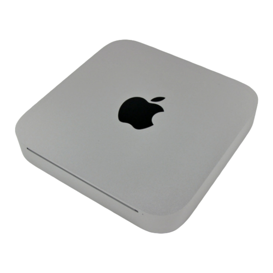
Well folks, after much clamor, it seems the engineers at
Apple have finally included an HDMI port in an actual
Apple product.
Notable Tech Specs:
2.4 or 2.66 GHz Intel Core 2 Duo processor
2 GB of RAM (expandable up to 8 GB)
NVIDIA GeForce 320M graphics processor with
256MB of shared DDR3 SDRAM (the same as
the most recent MacBook)
HDMI port with support for up to 1920-by-1200
resolution
AirPort Extreme 802.11n Wi-Fi wireless
networking
SD card slot
www.iFixit.com
Page 1 of 13
Advertisement
Table of Contents

Summary of Contents for iFixit Mac Mini Model A1347
- Page 1 Mac Mini Model A1347 Teardown Mac Mini Model A1347 Teardown Step 1 - Well folks, after much clamor, it seems the engineers at Apple have finally included an HDMI port in an actual Apple product. Notable Tech Specs: 2.4 or 2.66 GHz Intel Core 2 Duo processor...
- Page 2 Mac Mini Model A1347 Teardown Step 2 Contents of box: Mac Mini HDMI to DVI adapter Power cord Step 3 Departing from previous generations, the Mini's unibody top enclosure is machined from a single block of aluminum. Measuring 1.4 x 7.7 x 7.7 inches and weighing only 3 lbs, this is truly one for the books.
- Page 3 Mac Mini Model A1347 Teardown Step 4 The Mini's new port layout is indeed surprising: AC power in Built-in 10/100/1000BASE-T ethernet Firewire 800 HDMI Mini DisplayPort Four USB 2.0 ports, down one from the previous Mac Mini SD card slot...
- Page 4 Mac Mini Model A1347 Teardown Step 6 With a simple counter-clockwise twist, the black access plate can be removed for easy RAM and fan access. Gone are the days of the putty knife...you will be missed old friend... Step 7 Much like many other new Apple products, removing the RAM is quite feasible this time around.
- Page 5 Mac Mini Model A1347 Teardown Step 8 After removing two screws, the fan can be lifted out to access its power connector. The connectors inside this machine look pretty consistent with those found in Apple's current product lineup. Nothing too new here.
- Page 6 Mac Mini Model A1347 Teardown Step 10 The Wi-Fi antenna plate is held in place by four screws. After a good deal of wiggling, the antenna plate can be slid out from under the lip of the outer case. Step 11 The top Wi-Fi antenna connector is hidden underneath the antenna plate near the hard drive connector.
- Page 7 Thermal sensor cables Infrared board cable Step 13 Behold, iFixit's specialized Mac Mini Mid 2010 logic board removal tool! There are two blind holes in the case of the Mini that are meant for the ends of Apple's u-shaped logic board removal tool.
- Page 8 Mac Mini Model A1347 Teardown Step 14 Before completely sliding out the logic board assembly, the power supply connector must be disconnected. After disconnecting the power cable, the logic board assembly slides right out. Step 15 The top and bottom of the logic board and I/O frame assembly.
- Page 9 Mac Mini Model A1347 Teardown Step 16 Two screws secure the speaker assembly to the logic board. The Mini's 3/8" woofer dome won't be popping ear drums anytime soon. Step 17 Next to where the speaker was located, we find the AirPort Extreme card.
- Page 10 Mac Mini Model A1347 Teardown Step 18 A couple of spring-loaded T8 Torx screws secure the oddly shaped heat sink to the processors. In keeping with its space saving design, the fins directing air toward the vent hole are slanted to allow for better fan placement.
- Page 11 Mac Mini Model A1347 Teardown Step 20 The bare logic board. The brains of the unit feature: Intel P8600 2.4 GHz Core 2 Duo processor NVIDIA GeForce 320M graphics processor with 256MB of shared DDR3 SDRAM Other notable chips include:...
- Page 12 Mac Mini Model A1347 Teardown Step 22 The new Mini's power supply churns out a minuscule 7 Amps at 12V. Compare that to the 25.8 Amps at 12V cranked out by the iMac Intel 27". Like its iMac cousin, the Mac Mini finally says goodbye to external AC adapters.
- Page 13 Mini. Check it out if you want to see how Apple stashed the second hard drive. Thanks for following iFixit during this historic moment. Until next time! © 2010 iFixit — CC BY-NC-SA www.iFixit.com Page 13 of 13...


Need help?
Do you have a question about the Mac Mini Model A1347 and is the answer not in the manual?
Questions and answers