Grundfos S2 Installation And Operating Instructions Manual
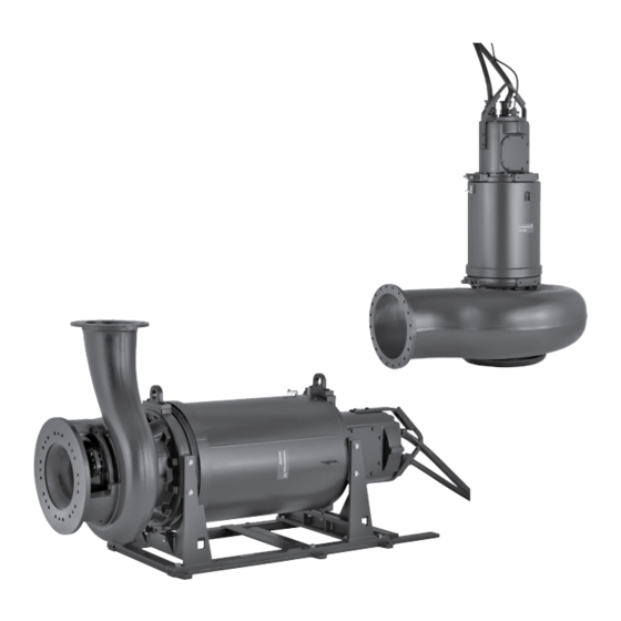
S pumps, ranges 72-74-78. 55-520 kw
Hide thumbs
Also See for S2:
- Installation and operating instructions manual (56 pages) ,
- Installation and operating instructions manual (38 pages) ,
- Installation and operating instructions manual (24 pages)

Related Manuals for Grundfos S2


Summary of Contents for Grundfos S2
- Page 1 GRUNDFOS INSTRUCTIONS S pumps, ranges 72-74-78 S2, S3, S4, ST 55-520 kW Installation and operating instructions...
-
Page 2: Table Of Contents
2. General description Wiring diagram for sensors This booklet includes instructions for installation, operation and Frequency converter operation maintenance of Grundfos submersible sewage and wastewater Startup S-range pumps with motors of 55 to 520 kW. Checking the direction of rotation Maintenance and service 10.1 Oil check and oil change... -
Page 3: Applications
2.1 Applications Warning S pumps, range 72, 74 and 78, are designed for the pumping of Special conditions for safe use of S pumps, sewage and wastewater in a wide range of municipal and range 72 Ex, 74 and 78: industrial applications. -
Page 4: Operating Conditions
Installation types C and S In special situations the temperature of the pumped liquid may be higher, if the motor is not Note fully loaded. If necessary, contact the nearest Grundfos company or service workshop. Ex pumps, installation type S Warning Explosion-proof pumps must never pump liquids with a temperature higher than 40 °C. -
Page 5: Identification
Please note that the pump type described in this booklet is not necessarily available in all variants. Code Example .250 .2250 .4 .72 .496 Pump type: Grundfos sewage and wastewater pump Multi-channel impeller pump installed in a column pipe Impeller type: Two-channel Three-channel Four-channel... -
Page 6: Nameplates
3.2 Nameplates 3.3 Approval plates, range 72 Fig. 4 Approval plates of explosion-proof S-pumps, range 72 The approval plate gives the following details: CE mark Baseefa 1180 ATEX-notified body identification number EU ex symbol Equipment group (II = non-mining) Equipment category (high protection) Type of explosive atmosphere (G = Gas) Explosion-proof motor according to European standard... -
Page 7: Safety
4. Safety 5. Transportation and storage The pump is supplied from factory on a steel transportation stand Warning in horizontal position. Pump and stand is protected by a special Pump installation in pits must be carried out by cover. specially trained persons. Work in or near pits must be carried out according to local regulations. - Page 8 Net weight [kg] Net weight [kg] Pump type Pump type S3.145.500.3150.10.78L 5900 5800 6300 Range 72 S3.145.500.3500.8.78L 6000 5900 6400 S2.90.250.2250.4.72S 1770 1950 1955 2250 S3.145.500.3500.10.78L 6200 6100 6600 S2.100.250.2250.4.72H 1760 1945 1955 2240 S3.145.500.4000.8.78L 6100 6000 6500 S2.100.250.1750.4.72H 1760...
-
Page 9: Raising Pump To Upright Position
5.2 Raising pump to upright position The weights are net weights including the Note accessories mounted from factory. Warning All lifting equipment must be rated for the purpose and checked Make sure that the lifting brackets are tightened for damage before any attempt to lift the pump. The lifting before attempting to lift the pump. -
Page 10: Storage
Prior to installation, check the oil level in the oil chamber, see section 10.1 Oil check and oil change. Warning We recommend that you always use Grundfos accessories to avoid malfunctions due to incorrect installation. Fig. 16 Auto-coupling base installation on pedestal... - Page 11 The correct pedestal heights (A) for installation on auto-coupling Installation type D appear from the following table. Permanent vertical dry installation. Required pedestal height (A) Pump type [mm] Range 72 S2.90.250.xxxx.x.x S2.100.250.xxxx.x.x S2.100.300.xxxx.x.x S3.110.300.xxxx.x.x S3.120.500.xxxx.x.x S3.135.500.xxxx.x.x S3.140.600.xxxx.x.x Range 74 S2.90.xx.xxx.xxxx.x.x S2.100.xxx.xxx.xxxx.x.x...
-
Page 12: Start And Stop Levels
Pumps for column pipe installation are installed permanently in a auto-coupling and operated completely or partially submerged in column pipe. Grundfos does not normally supply the column pipe. the pumped liquid. Dimensioning of the column pipes is suggested in the pump Before installing the auto-coupling base unit ensure the quality specific dimensional drawings. - Page 13 6.5 Dry installation Start levels In pumping stations with dry-installed pumps, set the starting Pumps in dry installation are installed permanently in a pump levels above the pump housing in order to ensure that the cooling room. jacket is filled up before the pump starts pumping. For vertical The pump motor is enclosed and watertight and will not be pumps, this height may be considerable and should be set with a damaged if the installation site is flooded with water.
-
Page 14: Io 113
7.1 IO 113 P1 P2 P3 P4 P5 I1 I2 I3 IO 113 forms interface between a Grundfos sewage and 1 2 3 4 5 6 7 8 9 1011 1213 14 wastewater pump with analog and digital sensors and the pump controller. - Page 15 7.3.2 Pt100 SM 113 IO 113 S pumps, ranges 72, 74 and 78 are equipped with Pt100 sensors Analog and digital in the stator windings, in the upper bearing bracket and in the outputs lower bearing bracket. Pt100 makes an analog measurement from 0-180 °C. The value is measured by the SM 113 and transferred to the IO 113 through serial communication.
-
Page 16: Electrical Connection
8. Electrical connection The supply voltage and frequency are marked on the pump nameplate. Make sure that the motor is suitable for the power supply available at the installation site. Warning Connect the pump to an external mains switch ensuring all-pole disconnection with a contact separation according to EN 60204-1, 5.3.2. -
Page 17: Wiring Diagram For Sensors
Wiring diagrams in the custom-built products may be different from the standard. In this case we recommend that Note you contact the nearest Grundfos company or authorized workshop. 8.3 Frequency converter operation In principle, all three-phase motors can be connected to a For frequency converter operation, please observe the following frequency converter. -
Page 18: Startup
8.3.1 Requirements 9. Startup • The thermal protection of the motor must be connected. Warning • Peak voltage and dU/dt must be in accordance with the table Before manual starting or changeover to below. The values stated are maximum values supplied to the automatic control, make sure that no persons are motor terminals. -
Page 19: Maintenance And Service
The maintenance and service work on explosion- Horizontal position proof pumps must be carried out by Grundfos or Proceed as follows: a service workshop authorized by Grundfos. 1. Place the pump in such a position that inspection screw (A) is Before carrying out maintenance and service, make sure that the pointing upwards. -
Page 20: Inspection And Adjustment Of Impeller Clearance
2. Place a clean container under the pump to collect all the 10.2 Inspection and adjustment of impeller clearance drained-off oil. Remove screw B and observe the oil level. The correct axial clearance is 1.3 mm ± 0.2. The clearance 3. - Page 21 Method 1 Method 2 Pump types Pump types Ranges 72 and 74 Ranges 72 and 74 S2.90.xxx.xxxx.x.xxx. S3.110.xxx.xxxx.x.xxx. S2.100.xxx.xxxx.x.xxx. S3.120.xxx.xxxx.x.xxx. S3.135.600.xxxx.x.xxx. S3.135.500.xxxx.x.xxx. Range 78 S3.115.xxx.xxxx.x.xxx. S3.130.xxx.xxxx.x.xxx. S3.145.xxx.xxxx.x.xxx. S4.135.xxx.xxxx.x.xxx. View from direction A Fig. 37 Impeller clearance, installation type D and H, method 2 These pump types have threaded holes in the suction cover (12a) for the fastening screws (35) as shown in fig.
-
Page 22: Contaminated Pumps
(maximum pressure 100 bar). If Grundfos is requested to service the pump, Grundfos must be Remove caked dirt from the motor to ensure good heat contacted with details about the pumped liquid, etc. before the conductivity. -
Page 23: Fault Finding Chart
This product or parts of it must be disposed of in an environmentally sound way: 1. Use the public or private waste collection service. 2. If this is not possible, contact the nearest Grundfos company or service workshop. Subject to alterations. - Page 24 TR Uygunluk Bildirgesi Vi, Grundfos, försäkrar under ansvar att produkterna S pumps, range 72, Grundfos olarak bu beyannameye konu olan S pumps, range 72, 74 ve 78 74 och 78, som omfattas av denna försäkran, är i överensstämmelse med ürünlerinin, AB Üyesi Ülkelerin kanunlarını birbirine yaklaştırma üzerine rådets direktiv om inbördes närmande till EU-medlemsstaternas...
- Page 25 ATEX approval plate and EC-type examination certificate. Further information, see below. This EC declaration of conformity is only valid when published as part of the Grundfos installation and operating instructions (publication number 98664739 1114). Székesfehérvár, 8th April 2014 Jannek Uldal Christensen D&E Central Europe, site manager...
- Page 26 Declaration of conformity RU Насосы типа S исполнения: S1, S2, S3, S4, SV, S1A, SVA, ST, SVX сертифицированы на соответствие требованиям Технических регламентов Таможенного союза: ТР ТС 004/2011 «О безопасности низковольтного оборудования»; ТР ТС 010/2011 «О безопасности машин и оборудования»; ТР ТС 020/2011 «Электромагнитная...
- Page 27 BH-71000 Sarajevo Turkey Siu Wai Industrial Centre Phone: +387 33 592 480 GRUNDFOS Pumper A/S GRUNDFOS POMPA San. ve Tic. Ltd. Sti. 29-33 Wing Hong Street & Telefax: +387 33 590 465 Strømsveien 344 Gebze Organize Sanayi Bölgesi 68 King Lam Street, Cheung Sha Wan www.ba.grundfos.com...
- Page 28 96604379 0315 ECM: 1135846 www.grundfos.com...
Need help?
Do you have a question about the S2 and is the answer not in the manual?
Questions and answers