Vdwall LVP615 series User Manual
Led hd video processor
Hide thumbs
Also See for LVP615 series:
- Quick user manual (8 pages) ,
- Operation application instruction (49 pages)
Table of Contents
Advertisement
Advertisement
Table of Contents

Related Manuals for Vdwall LVP615 series


Summary of Contents for Vdwall LVP615 series
- Page 1 LVP615 series LED HD Video Processor User Manual Contents...
-
Page 2: Table Of Contents
LVP615 series user manual Safety precautions 一、 -------------------------------------------------------- 4 Item list 二、 -------------------------------------------------------------------------- 5 三、Hardware connection 1、 Rear view-------------------------------------------------------------------------- 6 2、 Port description------------------------------------------------------------------ 6 3、 Hardware connection diagram----------------------------------------------- 8 4、 Specifications----------------------------------------------------------------------9 5、 Product dimensions--------------------------------------------------------------11 四、Front panel buttons and remote control instructions 1、... - Page 3 LVP615 series user manual 2、 Wired network-------------------------------------------------------------------- 51 3、 WIFI connection----------------------------------------------------------------- 52 (二)LVP615 series PC control software instructions---------------------- 59 1、 Control method------------------------------------------------------------------ 59 2、 Software interface instructions---------------------------------------------- 60 (三)APP remote control-------------------------------------------------------- 77 1、 Connection----------------------------------------------------------------------- 78 2、 APP control instructions-------------------------------------------------------81 Notes about model ------------------------------------------------------------- 98 八、...
-
Page 4: 一、 Safety Precautions
LVP615 series user manual 一、 Safety precautions !Danger There is high voltage in the processor, to prevent any unexpected hazard, unless you are maintenance, please do not open the cover of the device. !Warning 1. This device shall not encounter water sprinkle or splash, please do not place anything containing water on this device. -
Page 5: 二、 Item List
LVP615 series user manual The device is dropped down or cabinet is damaged. Obvious malpractice is found or performance degrades. 二、 Item list Please unpack the product carefully, then check whether all the following things are included in the package. If anything is found missing, please contact the dealer. -
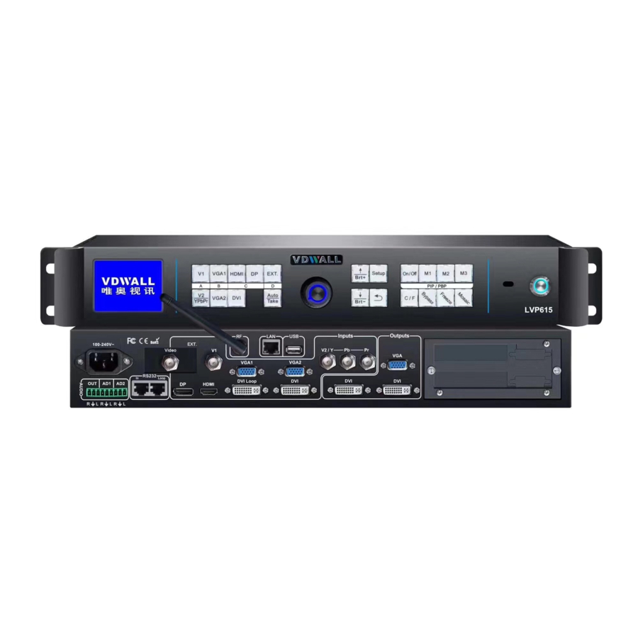
Page 6: 三、Hardware Connection 1、 Rear View
LVP615 series user manual (only for LVP615D) use. Please remove from processor avoid damage. 三、 Hardware connection 1、 Rear view 2、 Port description 1) Video signal input(INPUTS) LVP615 supports 8 video signals input as follows: Port Description 1*Composite Video (PAL/ NTSC) - Page 7 LVP615 series user manual EXT. 1* Extended input port Note EXT.input standard VIDEO, optional : 1*SDI/HD-SDI/3G-SDI or 1* VGA/DVI/HDMI port. 2) Audio input signals(AUDIO) LVP615 supports 5-channel stereo audio inputs switching. Of which, 3 channels are DP, HDMI and SDI input. The other 2 channels are AD1, AD2 external audio input.
- Page 8 LVP615 series user manual interface USB communication port Serial communication interface, used to RS232 IN connect the RS232 port of PC to realize PC software control. Serial communication cascading output for connecting the RS232 IN of next unit, RS232 LOOP through single PC can control several units.
-
Page 9: Specifications
LVP615 series user manual 4、 Specifications Inputs 2×Video 1×YPbPr Nums / Type 2×VGA(RGBHV) 1×DVI(VESA /CEA-861)... - Page 10 LVP615 series user manual 1×HDMI(VESA /CEA-861) 1×DP(VESA) 1×EXT.(Extended) Video system PAL/NTSC Composite Video 1V(p_p)/ 75Ω Amplitude Impedance VGA format PC(VESA standard) ≤2048×1152_60Hz Amplitude R、G、B = 0.7 V(p_p)/ 75Ω Impedance YPbPr format SD/HD(CEA -861) ≤1920x1080p_60Hz Y=1V(p_p)/ 75Ω YPbPr Amplitude Pb= 0.35V(p_p)/ 75Ω...
-
Page 11: Product Dimensions
LVP615 series user manual 1024×768_60Hz/75Hz 1280×1024_60Hz/75Hz 1600×1200_60Hz 1920×1080p_50Hz/60Hz 1366×768_60Hz 1440×900_60Hz 2048×1152_60Hz VGA/DVI format 2560×816_60Hz 2304×1152_60Hz 1920×1200_60Hz 1200×1600_60Hz 1080×1920_60Hz 1536×1536_60Hz Custom output format(maximum horizontal pixel:3840, maximum vertical height:1920) VGA OUT:15Pin D-sub( female) Output connectors DVI OUT1:24+5 DVI_I DVI OUT2:24+1 DVI_D Others... - Page 12 LVP615 series user manual RS232 cable order:...
- Page 13 LVP615 series user manual 四、 Front panel buttons and remote control instructions LVP615 supports front panel button, remote control, RS232 and LAN...
-
Page 14: Front Panel Buttons And Remote Control Schematic
LVP615 series user manual control. Same printing on reomote control buttons and front panel buttons,same button functions. The instructions are as below. 1、 Front panel buttons and remote control schematic The buttons on remote control have the same functions as the relative buttons on front panel. - Page 15 LVP615 series user manual ):select the input signal. , 2) Setup buttons( ): Setup the , output image parameters. 3) VGA auto adjustment button( ): automatically adjust the VGA input signal. 4) Switching time setup button( ):select seamless switching time including 0 second (cut), 0.5 second,1.0 second and 1.5 second ( fade in fade out) and blend switching function.
-
Page 16: Remote Control Operation Instructions
LVP615 series user manual 9) Brightness adjustment button ( ) adjust output brightness , level under user operation station. 10) remote control sensor: built in infrared receiver. 11) remote launch window: built-in infrared transmitter. 2、 Remote control operation instructions 1) Open the battery compartment on the back of the remote control,... - Page 17 LVP615 series user manual 五、 Basic User Instructions After LVP615 starting, it enters the operation status of last shut-down including signal switching status, PIP/POP (or Text overlay) status and mosaic status. Among them, PIP/PBP( or text overlay) status and mosaic status can only realize relative functions and cannot do other operation.
- Page 18 LVP615 series user manual 1 * HDMI digital signal input 1* DisplayPort digital signal input 1* extended signal input Note : (1) YPbPr and V2 share the same port and signal. If need,configure the port to YPbPr in setup menu if need.
- Page 19 LVP615 series user manual current input signal. Like: “ Input:HDMI ” 。The second line on the LCD display the signal status.If no active input, display” No input’. Meanwhile,the corresponding indicator flicker. Led screen is black. If active input, display input signal format Like:“ 1080p_60Hz ” 。...
- Page 20 LVP615 series user manual Note:Pre.+Take switch only available for seamless switching. LVP615 supports seamless switching between any two different input groups as follow. Same group does not support seamless switching. For example, current input is V1( V1 in group A). Then, preselect signal is only from B,C,D group.
-
Page 21: Pip/Pbp Operation
LVP615 series user manual or main signal button again. Then switch to selected signal. The whole process is fade in fade out effect. Main Input: HDMI Main In Status: 1080p_60Hz Blend Input: Blend In Status: -------------------------------------- Output size: 1920x1080 Output start: (0,0)... -
Page 22: Mosaic Operation
LVP615 series user manual Main Input: HDMI Main In Status: 1080p_60Hz PIP Input: PIP In Status: -------------------------------------- Main Output Size: 1920x1080 Main Output Start: (0,0) PIP Output Size: 640x320 PIP Output Start: (16,16) Select PIP input signal : In PIP mode , press button to select corresponding signal. -
Page 23: Other Basic User Operation
LVP615 series user manual Mosaic Input: In Status: 1080p_60Hz Input Image Size: 960x540 Input Image Start: (0,0) -------------------------------------- Mosaic out size: 1920x1080 Mosaic out start: (0,0) Mosaic PIP: -------------------------------------- Device ID: Note: 1) In mosaic mode, PIP display is available. - Page 24 LVP615 series user manual 2) VGA input auto adjustment (Auto) When LVP615 is in one key switch status and current valid input signal is VGA, press Auto button to adjust VGA input signal sampling parameters. Then the VGA output image can be clear and full.
- Page 25 LVP615 series user manual LVP615 allows for overlapping text, logo or flash on the current image. The operation is as below. When the current input display properly, enter setup menu“3.Text overlay” , set ”3.1text overlay” on , then select text source.Text can be produced by Powerpoint and other office software.
- Page 26 LVP615 series user manual 六、 Setup menu instructions Setup menu is to set the entire processor. There are 9 section including output image 、 input image 、 text overlay 、 image quality 、 audio 、 communication、language、advance、PIP/PBP、mosaic. setup -------------------------------------- 1. Out Image >>...
- Page 27 LVP615 series user manual Press Setup to enter setup menu. Press ↑,↓ button to select“1.Out image” item.Then press OK button to enter the following image“1.Out image” item. 1.Out Image -------------------------------------- 1.1 Resolution 1920x1080_60 1.2 Out Width 1920 1.3 Out Height 1080 1.4 Out H_Start...
- Page 28 LVP615 series user manual Tips -------------------------------------- Data will reset Press <OK> to restart Press <return> to cancel Note: to custom output format,after selection,need further set 1.1.1 custom width、 1.1.2 custom height and 1.1.3 custom V frequency. Press ↓ button to 1.1.4 Apply , Press “OK”to make parameters effective.
- Page 29 LVP615 series user manual LED screen real resolution can be arbitrary. So we need set LVP615 to output the same image as the led screen. Then the LED screen can display whole image. (0,0) _out_hori_start Out_hori_width Out_vert_start LVP615 output image area...
-
Page 30: Input Video Signal Setting
LVP615 series user manual LVP615 can generate 36test patterns for LED screen testing. If this item value is “off”, turn off Test pattern. Select other number and confirm.Then one corresponding test pattern of 36 pcs will be selected. Operation steps:... - Page 31 LVP615 series user manual Press Setup button to enter setup menu. Press↓ button to select 2. Input video signal and press OK to enter this item. 2.Input video signal -------------------------------------- 2.1 DVI EDID 1280x1024_60 2.2 V1/V2 backup 2.3 VGA1/VGA2 backup 2.4 HDMI/DVI backup...
- Page 32 LVP615 series user manual 2) Hot spare setting LVP615 supports hot spare of input signals. When the current input signal is lost. LVP615 will switch to the spare signal automatically to avoid image interruption caused by the fault of signal source.
-
Page 33: Text Overlay Setting
LVP615 series user manual 2.Input video signal -------------------------------------- 2.1 DVI EDID 1280x1024_60 2.2 V1/V2 backup 2.3 VGA1/VGA2 backup 2.4 HDMI/DVI backup 2.5 V2 or YPbPr 2.6 switch mode Pre.+Take SW. ? 3、 Text overlay setting 3.Text overlay -------------------------------------- 3.1 Text overlay 3.2 Text source... - Page 34 LVP615 series user manual overlay is on. If need turn it off, enter 3.1 text overlay and switch if off. 2) Text overlay parameters setting 3.1Text mode:LVP615 can custom text mode < threshold or > threshold. < threshold means text signal image which is less than the current threshold value will overlay on the current signal.
- Page 35 LVP615 series user manual 4、 Color& Brightness,etc. 4.Color&Brightness Default -------------------------------------- 4.1 Input color V1=50 V2=50 HDMI=50 DVI=50 DP=50 EXT=50 V1=50 All=50 4.2 Sharpness normal 4.Color&Brightness Default -------------------------------------- 4.3 Brightness LVP615 supports custom color,sharpness and brightness setting. List as follow: Item name Definition Adjustment range:0~100,...
-
Page 36: Audio Setting
LVP615 series user manual 0-64 and default is 64.“Brightness level” can be set in factory setting. Note : 1). To make sure of full gray scale of output image, these output parameters are set as default. 2).Color parameters are invalid for RGB format DP, DVI and HDMI. -
Page 37: Communication Setting
LVP615 series user manual 6、 Communication 6.Communication -------------------------------------- 6.1 IP: 192.168.1.8 6.2 mask: 255.255.255.0 6.3 gate: 192.168.1.1 6.4 Mac: 76:64:77:00:00:00 -------------------------------------- 6.5 device ID LVP615 can be remotely controlled via Ethernet. Communication setting menu is used to set network parameters including IP address, mask, gate, MAC and number the multiple LVP615 under the same IP. -
Page 38: Advance Setting
LVP615 series user manual 7. Language -------------------------------------- 7.1 语言 Language Chinese 8、 Advance setting 8.advance default -------------------------------------- 8.1 ADC calibration OK to apply 8.2 Bias 8.3 EXT.Input model EXT.VIDEO 8.4 De-Interlace 8.5 Bright level 0-64 8.6 DVI hotplug 8.7 Wifi reset OK to apply 8.8 Device reset... - Page 39 LVP615 series user manual leaving factory. Please use this item carefully. 2) Gray scale To reduce noise of low gray scale images, LED display system normally will remove the low gray scale part from input signals. But this will also bring information loss of images, especially dark images like night scenes.
- Page 40 LVP615 series user manual Bright Description level 0-64 0 is minimum brightness, 64 is default standard brightness. 0-100 Allow higher brightness value: 0 is minimum and 50 is default value. According to different demands, user can select relative “Bright Level”.
-
Page 41: Pip/Pbp Setting
LVP615 series user manual Enter “8.8 Device Reset” and press OK button, there is one information on LCD screen to remind you data will reset. Press OK to apply. LVP615 will reset and restart. 9、 PIP/PBP setting D.PIP/PBP Mode=M1 -------------------------------------- D.1 Main Width... -
Page 42: Mosaic Setting
LVP615 series user manual The setup option is used to set LVP615’s three user defined PIP/PBP mode. Operation as below: When LVP615’s PIP/PBP status is open (the indicator light on “On/Off” button is lit up), press Setup button, LVP615 enters “D. PIP/PBP” menu. Then press mode button (M1, M2 or M3) to select a mode to save parameters, press ↓... - Page 43 LVP615 series user manual E.Mosaic(Video Wall App) -------------------------------------- E.9 In Width E.10 In Height E.11 In H_Start E.12 In V_Start E.13 Out Width 1920 1920 E.14 Out Height 1080 1080 E.15 Out H_Start E.16 Out V_Start LVP615 can maximally output 2304*1152 or customized resolution with maximal horizontal 3840 pixels or vertical 1920 pixel.
- Page 44 LVP615 series user manual E.4 unit height resolution and position E.5 unit horizontal compared with the whole spicing screen driven by start Automa this unit of LVP615 E.6 unit vertical start E.7 sync. splicing ON or OFF of the sync...
- Page 45 LVP615 series user manual screen) of LED screen the LVP615 drives; In the menu E.7 sync. Mosaic menu, select to turn the function on or off; In the menu E.8 auto Calculation, press OK, LVP615 starts to mosaic automatically; Observing image splicing effect. If any problem, enter fine adjustment menu option E.9~E.16 to adjust image.
- Page 46 LVP615 series user manual 3456 System Topology Input signals 1920 LVP615#0 LVP615#1 LVP615#3 LOOP OUT LVP615#2 LVP615#4 LOOP OUT As above diagram shows, all input signals are connected to and switched by #0 LVP615. The 2 same DVI outputs of #0 LVP615 are connect to #1 LVP615 and #2 LVP615.
-
Page 47: 一)Hardware Communication
LVP615 series user manual splicing In order to ensure all output images are synchronous to each other, please note the following settings: 1. The input signals can be only DVI signals, and if the processor is in mosaic mode, it will be unable to switch input signals;... -
Page 48: Wired Network
LVP615 series user manual RS232 port, USB control method can be used. RS232 or USB LVP615 2、 Wired Network Because LVP615 built-in network convert RS232 module, after wired network connecting LAN and setting relative network configuration parameters (refer user manual page “6. -
Page 49: Wifi Connection
LVP615 series user manual Network cable Work station1 Network cable Router WIFI LVP615 Work station 2 3、WIFI Connection LVP615 is built in WIFI module. Through this module, user can achieve WIFI remote control of LVP615. The module supports 2 WIFI connection methods: First., Wireless Router, another wireless device connects the module directly... -
Page 50: Control Method
LVP615 series user manual There are relative setups and instruction about LVP615 WIFI module and how to realize the 2 control methods as below: NOTICE: When using WIFI connection, WIFI ANTENNA must be installed. 3) WIFI Connection Module Using laptop with wireless network, open network and share center, search... - Page 51 LVP615 series user manual Configuring network be automatically obtain IP address and DNS server address, show as the picture below: Note: if can’t connect, entering setup menu “8.7Wifi reset” to reset WIFI module (refer user manual page 48), then restart and connect.
- Page 52 LVP615 series user manual (1) Running wireless scan configuration software “LVP615 WIFI Config Tool.exe”, the application software as the picture as below. (2)Click “Scan” to search LVP615 in the local area network, after searching module the information display as below.
- Page 53 LVP615 series user manual name (default name is admin) and password (default password is admin), software will remind “module identify successfully” and “obtain configuration parameter successfully”, meanwhile software interface will display relative information. ( 4 ) Now you can configure module. Configuration options include Mode Setting, AP Setting, STA Setting, Serial Port Parameter Setting , Socket Setting and Advanced setup.
-
Page 54: Connection
LVP615 series user manual b. AP Setting and STA Setting After selecting the mode, we need to configure specific parameters for the mode. See as below: AP Setting Click “Search” button, you can find surrounding wireless network network STA Setting... - Page 55 LVP615 series user manual address changes. c. Serial Port Parameter Setting This step is for setting basic parameters of serial port, after modifying configuration, click “save” button to save change. As the picture below shows, the Baud Rate should be 9600.
- Page 56 Please set according to needs. See the picture below: (二) PC Control Software Instruction of LVP615 Series LVP615’s control software used to control LED HD video processor LVP615. Through the software, we can realize: ...
- Page 57 LVP615 series user manual As illustrated above, the PC remote control of LVP615 can realize connection by RS232, USB, LAN or WIFI. After connecting and needed configuration, we can run the control software: “LVP615 Control Software.exe” 2、 Introduction of Software Interface...
- Page 58 LVP615 series user manual Information Timing Control Setting Output Parameters Setting(Screen Setting) Multi Units Cascading Splicing Setting(Quick Mosaic) Output Resolution Setting 1) Communication Setup In communication setup, first select connection method being Serial or network. If select serial, need to select correct COM port, can check COM port number in PC’s “device manager”, show as the picture below:...
- Page 59 LVP615 series user manual controlled. If select network connection, firstly must set the network connected being correct, the relative setup about wired network prefer 6. Communication (user manual page 46), wireless network setup refer user manual page 53. In IP address and port number option type in correct setup, the default setup of wired network and wifi AP mode refer the table as below.
- Page 60 LVP615 series user manual The buttons of the signal area respectively represent the corresponding keys and status indicators in the panel of the processor. After the device is successfully connected, the software will read the input signal source you currently selected and the blue indicator above it will turn on. If the blue indicator illuminates normally, it means the input signal source you currently selected is valid;...
- Page 61 LVP615 series user manual TEXT: text overlay display switch, used open or close text overlay function; meanwhile the bright point above the button indicates the function is open or not. BYPASS: full and part display switch button, only available for PC signal VAG DVI HDMI Freeze:...
- Page 62 LVP615 series user manual preset timer plan. The system provides four cycle timer modes, i.e.: Day, Week, Month, Once. Start timing: Start: open timing control function Stop timing: stop timing control function Timer<<: spread or shrink timing execution list on right side.
- Page 63 LVP615 series user manual Cycle Plan is sub-divided into three types: (1)Day plan(timing in one day) (2)Weekly plan (timing in one week) (3)Monthly plan(timing in one month) User can select one type he desires The plan items of Day Plan define hours, minutes, seconds;...
- Page 64 LVP615 series user manual 6) Setting output date In user main interface click Setup, appearing the setup interface of output parameter, in the interface user can set output parameters of processor. As shown in above figure, the button “Refresh” is used to update the information of currently processing parameters after parameters configuration is finished.
- Page 65 LVP615 series user manual Show as the picture Screen output parameters include these parts as below: (1)Image input/output parameters configuration and mosaic mode setup The parameters of output windows should be configured to the actual pixels of the screen to be driven.
- Page 66 LVP615 series user manual (2)PIP/PBP display setup (location and size of PIP windows) This menu is used to set the three PIP/POP display modes of LVP605,first, select a PIP mode to be adjusted, then enter the parameters of background, location and size of PIP windows, then click “Save”...
- Page 67 LVP615 series user manual These options is used to set brightness, color, bias and sharpness of output image, after save reset typing in desired parameter click button to save, or click button to reset parameters being default value. Directly click “Normal” or “Sharp”, the parameters will be saved.
- Page 68 LVP615 series user manual You can select this terminal as V2 or YPbPr. (8)Multi units cascading splicing rapid setup LVP615 can drive ultra high-definition LED display through multi-machine cascade mosaic. User can complete input/output parameters configurations of each ser of processor through fast mosaic menu.
- Page 69 LVP615 series user manual Caution: before making the mosaic settings, please make sure the following conditions have been met: (1)All processors are the same with each other in brightness, color, contrast and definition. All processors must use the same output resolution, and make sure it the same with that of input DVI signals.
- Page 70 LVP615 series user manual adjusted via serial ports. (1)Using software connect processors Select the device ID of the first processor to be adjusted (from user setup item 6.5 “Device ID”), click “Connect”, the processor will automatically connect the processor, the software will read and display the current parameters (e.g.: output resolution) of the processor.
- Page 71 LVP615 series user manual current processor. Caution: both input and output parameters of LVP615 must be even, but the results of auto calculation may be odd, if so, it is necessary to set an adjusted value to correct the parameters to be even, then you can click “Set” to save it.
- Page 72 LVP615 supports to be controlled by mobile device for example tablet computer and mobile phone. User can download the APP from our company VDWALL, 并 进 行 安 装 , IOS platform can download and install the APP by link:https://itunes.apple.com/cn/app/lvp615/id1129709980?mt=8 下...
- Page 73 LVP615 series user manual 1、 Connection Firstly, through local area network (LAN interface) or WIFI connect LVP615 and mobile device installed APP. In here we illustrate by using router function of LVP615’S wifi module. Open wireless LAN switch of IOS device, in the network searched out, connect the WIFI hot point named LVP615, the default password is 88888888.
- Page 74 LVP615 series user manual Connection button Click connect ,If the communication is normal,this button’s color will change into green from gray. Click connect Connect successfully If connect unsuccessfully, click communication option in adjustment setup, to make sure...
- Page 75 LVP615 series user manual the setup is correct or not. Make sure the port and Click connect Click communication IP address is correct...
- Page 76 LVP615 series user manual 2、 APP Operation After connection is successful, through software, users can control LVP615, displaying as the guide interface above, APP has four function areas: operation control, setting, Mosaic setting and...
- Page 77 LVP615 series user manual information. Single click guide interface, the corresponding buttons will enter selected function interface. We illustrate the four function areas respectively as below. 1) Operation and Control The main functions of operation control interface include: signal switch, PIP/PBP, Text overlay and other functions.
- Page 78 LVP615 series user manual LVP615 could support one button switch and Preselect+Take Switch. Signal Selection Area Switching mode selection switching time selection...
- Page 79 LVP615 series user manual Signal Switching Mode Selection In operation interface click signal switch mode, pop the interface as below, click to select appropriate switch mode.
- Page 80 LVP615 series user manual Switching Time Selection In operation interface, click switching time, popping the interface as below, click appropriate switching time. One button switch LVP615’s default signal switching mode is that clicking corresponding s button in signal source selection area to switch...
- Page 81 LVP615 series user manual signal. Preselect+Take Switch The switch method’s interface as below, preselect firstly through signal source button,then through TAKE button to switch input signal source; blue button indicates current signal, green button indicates preselected signal source.
- Page 82 LVP615 series user manual (2) PIP Display...
- Page 83 LVP615 series user manual PIP operation interface as the picture above, operation steps:...
- Page 84 LVP615 series user manual Firstly in operation interface click PIP to open PIP function, then click PIP signal in popping PIP signal selection interface; through mode button ( M1,M2,M3 ) , Users could select corresponding display mode. Click PIP setting in popping setting interface, users can set the location and size of main...
- Page 85 LVP615 series user manual Interface of PIP Signal selection...
- Page 86 LVP615 series user manual User input specific parameters of main window and PIP window. Press + and - to adjust. Sketch map of main and PIP window’s location size. By multi-point touching in the area, user could zoom in and zoom image;...
- Page 87 LVP615 series user manual Text Overlay Operation Interface is as above, operation steps as followings: Firstly in operation interface click text overlay to open the function, then click text signal select relative input signal in popping interface; if needy to set the text threshold and other parameters, users could click text setting in popping interface.
- Page 88 LVP615 series user manual (4) Other Functions Bypass: Corresponding with the button BYPASS on front panel, namely part or full display function button. Freeze: Corresponding with the button Freeze on front panel; namely image freeze function button. Mosaic: Corresponding with the button Mosaic on front panel,namely splicing function button.
- Page 89 LVP615 series user manual (1) Output Resolution...
- Page 90 LVP615 series user manual Select the appropriate resolution in output resolution menu. And click setting, the processor will change to new resolution. If selecting custom resolution, user needs to set the corresponding width, height and frame frequency. (2)Output Image Parameter...
- Page 91 LVP615 series user manual The interface is used to set the location and size of output image, user could enter parameter manually, then through + and - to adjust parameters, in diagram area of output parameters, through multiple-point touching to zoom in or zoom out image size, single-point touching to drag and adjust image location.
- Page 92 LVP615 series user manual (4)Image quality...
- Page 93 LVP615 series user manual Reset is used to return to default value In image quality interface, users could set LVP615 output brightness, sharpness, bias and set every input signal’s color independently. (5) Audio...
- Page 94 LVP615 series user manual Audio setting interface could set LVP615’s corresponding input signals of two audio inputs, in order to achieve audio and video synchronous switch. (6) Network Setting Network setting menu is used to input network parameter of LVP615, this is the premise of remote control.
- Page 95 LVP615 series user manual LVP615 remote control APP only support Chinese and English interface presently, click language and exit language setting interface, then the language selected will be applied. Mosaic setting 3) Step1. Enter the size of whole screen, and the size and location of the processor in use Step2.
- Page 96 LVP615 series user manual To achieve splicing function before entering Mosaic, need to make sure these settings as below. (1) The current input signal is DVI (2) The resolution of DVI input signal must be as same as the output resolution of processor (3)...
- Page 97 LVP615 series user manual 4) Information display The interface includes the APP-controllable model, APP version information and company information.
-
Page 98: Copyright Information
LVP615: with VIDEO extended model 八、 Copyright Information The copyright of this Manual is owned by SHENZHEN VDWALL CO.,LTD., unless with prior consent of VDWALL, nobody is permitted to copy or use any part or all of the information contained herein.
Need help?
Do you have a question about the LVP615 series and is the answer not in the manual?
Questions and answers
How can we get the processor to reflect the whole picture instead of several small images ?
The Vdwall LVP615 series processor displays the entire picture as a whole instead of multiple small images by using a synchronization and mosaic function. The process involves:
1. Signal Input and Distribution: All input signals are connected to and switched by the primary processor (#0 LVP615). The same DVI outputs from #0 LVP615 are then looped to other processors (#1, #2, #3, and #4).
2. Image Cropping and Scaling: Each processor (#1 to #4) crops and scales a portion of the image according to predefined parameters. The total LED width is set to 3456 pixels, and the total height is 1920 pixels. Each unit covers a specific section of the display.
3. Mosaic Function: The processors are configured with the correct horizontal and vertical start positions (E.6 and E.7) to ensure that each unit only processes its assigned part of the image.
4. Synchronization: The mosaic function is enabled, and synchronization is turned on to ensure that all output images align correctly without delays or mismatches.
5. Automatic Calculation and Adjustment: The APP calculates and applies the parameters automatically, and manual adjustments can be made if needed.
By following these steps, the processors work together to output a seamless, synchronized image that spans across multiple LED screens, displaying the entire picture as a whole.
This answer is automatically generated