Raymarine ST60 Compass Instrument Owner's Handbook Manual
Hide thumbs
Also See for ST60 Compass Instrument:
- Owner's handbook manual (64 pages) ,
- Operating manual (38 pages) ,
- Commissioning manual (24 pages)

Related Manuals for Raymarine ST60 Compass Instrument


Summary of Contents for Raymarine ST60 Compass Instrument
- Page 1 ST60 Compass Instrument Owner’s Handbook Document number: 81107-4 Date: 1 April 2004...
- Page 2 Raymarine, ST60 and SeaTalk are trademarks of Raymarine Limited © Handbook contents copyright Raymarine Limited 2004...
-
Page 3: Emc Conformance
Handbook information To the best of our knowledge, the information in this handbook was correct when it went to press. However, Raymarine cannot accept liability for any inaccuracies or omissions it may contain. In addition, our policy of continuous product improvement may change specifications without notice. - Page 4 ST60 Compass Instrument Owner’s Handbook...
-
Page 5: Table Of Contents
Preface Contents Preface ........................i Important information ..................i Safety notices ..................i EMC conformance ................... i Handbook information ................i Contents....................iii Introduction ....................vii Data inputs ....................vii SeaTalk ....................viii Stand alone operation ................viii Remote control .....................viii Mounting options ..................viii Parts supplied ....................ix Chapter 1: Operation ....................1 1.1 Getting started .................. - Page 6 ST60 Compass Instrument Owner’s Handbook Technical support ..................11 World wide web ................11 Telephone help line ................11 Help us to help you .................11 Chapter 3: Installation ..................13 3.1 Planning your installation ..............13 Site requirements .................13 Transducer ..................13 Instrument ..................14 EMC installation guidelines ..............15 Suppression ferrites ................16...
- Page 7 Preface Master/repeater status ................. 30 Leaving Intermediate calibration ............31 4.4 Dealer calibration ................. 31 Calibration on/off ................. 32 Pointer response .................. 32 Heading display response ..............32 Boat show mode .................. 32 Factory defaults ..................32 Leaving Dealer calibration ..............33...
- Page 8 ST60 Compass Instrument Owner’s Handbook...
-
Page 9: Introduction
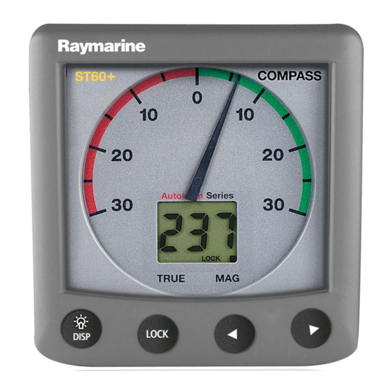
• Course Over Ground (COG). • Average Heading. The ST60 Compass instrument is constructed in a rugged weather proofed case. It provides a sensitive and stable, combined analog and digital display, to deliver accurate information under even the most demanding conditions. -
Page 10: Seatalk
SeaTalk network. Stand alone operation In Stand alone operation, the ST60 Compass instrument is connected only to the relevant transducer and does not display information from, or provide information to, any other instruments. -
Page 11: Parts Supplied
Preface Parts supplied Unpack your ST60 instrument and check that the following items are present: • Item 1, ST60 Compass instrument with standard bezel. • Item 2, Fixing studs (2). • Item 3, Thumb nuts (2). • Item 4, Gasket. - Page 12 ST60 Compass Instrument Owner’s Handbook COMPASS ST60 Steering Compass Instrument Owner's Handbook D4444-3...
-
Page 13: Chapter 1: Operation
2. Carry out the linearization procedure. Displayed information The information displayed on the ST60 Compass instrument is presented by means of a pointer and a digital display. The pointer gives a steering indication and the digital display shows the compass heading. -
Page 14: Pointer
Note: Use with Sea Talk autopilot If the ST60 Compass instrument forms part of a system which includes a Sea Talk autopilot operating in Auto, Vane or Track mode, the ST60 Compass instrument is forced to operate in Auto mode. -
Page 15: Unlocked Mode
Press the disp key to select COG. Provided you have GPS or similar positioning data on the SeaTalk system, the ST60 Compass instrument displays your course over the ground. If such data is not available the digital display shows “---”. -
Page 16: Locked Mode
ST60 Compass Instrument Owner’s Handbook Switch on Normal display TRUE disp disp Note: Modes marked * rely on external data. Press Course Over Average Ground* (COG) heading* for 3 seconds to reset average TRUE TRUE disp Using the disp key... -
Page 17: Operation
Chapter 1: Operation Operation Locked mode operation To enter locked mode (see the illustration), press the lock key. The current heading is applied as the locked heading and flashes for 5 seconds, after which time the heading display shows either the locked heading or the current heading, depending on what has been set up during User Chapter 4, Calibration calibration, as the normal display in locked mode (see... -
Page 18: Auto Mode
The average course error is reset to zero whenever the locked heading is changed. Auto mode The auto mode is activated automatically when the ST60 Compass instrument is connected to a SeaTalk compatible autopilot. LOCK Auto lock display... -
Page 19: Remote Control
Man overboard/reciprocal course If the vessel is turned through 110° or more when the ST60 Compass Instrument is in lock mode, the ST60 Compass Instrument automatically locks to the reciprocal of the original course (180° from the original). The digital display shows the reciprocal course and the pointer shows the course error from the reciprocal course. - Page 20 ST60 Compass Instrument Owner’s Handbook...
-
Page 21: Chapter 2: Maintenance & Troubleshooting
Chapter 2: Maintenance & Troubleshooting 2.1 Maintenance Servicing and safety • Raymarine equipment should be serviced only by authorized Raymarine ser- vice technicians. They will ensure that service procedures and replacement parts used will not affect performance. There are no user serviceable parts in any Raymarine product. -
Page 22: Troubleshooting
All Raymarine products are subjected to comprehensive test and quality assurance programmes prior to packing and shipping. If a fault arises with the ST60 Compass instrument, the following table may help to identify the probable cause and provide the most likely cure. -
Page 23: Technical Support
Please visit the Customer Support area of our web site at: • www.raymarine.com As well as providing a comprehensive Frequently Asked Questions section and servicing information, the web site gives e-mail access to the Raymarine Technical Support Department and a details of the locations of Raymarine agents, worldwide. - Page 24 ST60 Compass Instrument Owner’s Handbook...
-
Page 25: Chapter 3: Installation
Chapter 3: Installation Chapter 3: Installation This chapter describes how to install the ST60 Compass instrument and associated Fluxgate Compass transducer. The transducer cable is connected to the rear of the instrument. For advice, or further information regarding the installation of these products, please contact the Raymarine Product Support Department or your own National Distributor. -
Page 26: Instrument
ST60 Compass Instrument Owner’s Handbook The Fluxgate Compass transducer must also be sited: • At least 0.8 m (2 ft 6 in) away from the vessel's steering compass to avoid deviation in both compasses. • On a bulkhead below deck. -
Page 27: Emc Installation Guidelines
ST60 instrument dimensions D5785-4 EMC installation guidelines All Raymarine equipment and accessories are designed to the best industry standards for use in the recreational marine environment. Their design and manufacture conforms to the appropriate Electromagnetic Compatibility (EMC) standards, but correct installation is required to ensure that performance is not compromised. -
Page 28: Suppression Ferrites
Raymarine equipment. Always use the ferrites supplied by Raymarine. D3548-6 Connections to other equipment If your Raymarine equipment is to be connected to other equipment using a cable not supplied by Raymarine, a suppression ferrite MUST always be attached to the cable near the Raymarine unit. -
Page 29: Procedures
If you have ordered the flush mounting option, a low-profile bezel and four fixing screws are also provided. Fitting the instrument The ST60 Compass instrument can be installed using one of a number of different mounting options: • Surface Mounting. Gives a profile of approximately 0.95 in (24 mm). -
Page 30: Flush Mounting
ST60 Compass Instrument Owner’s Handbook Surface mounting D4328-2 3. Drill out the two 0.2 in (5 mm) fixing stud clearance holes (2). 4. Cut out the clearance hole (3) then remove the template. 5. Peel off the protective sheet from the self-adhesive gasket (4) then stick the gasket into position on the rear of the instrument. - Page 31 Chapter 3: Installation D4537-2 Fitting the low-profile bezel 3. Referring to the illustration, place the instrument face upwards on a flat surface and place the rubber keypad (7) in position around the display window (i.e. so that each key outline is located over its associated key on the instrument).
-
Page 32: Flush Mounting Procedure
ST60 Compass Instrument Owner’s Handbook CAUTION: It is essential that only screws of the correct size are used to secure the instrument to the bezel. Failure to observe this caution could result in damage to both the instrument and the bezel. -
Page 33: Bracket Mounting
Mounting Bracket Instruction Sheet. Fitting transducer If you are fitting an ST60 Compass instrument and wish to use it as a stand alone instrument, you need to fit a Fluxgate Compass transducer. If the ST60 Compass instrument is to form part of a system which includes a SeaTalk... -
Page 34: Running Transducer Cable
ST60 Compass Instrument Owner’s Handbook 3. If there are no differences, greater than 10° on any heading, then the site is suitable for the Fluxgate Compass transducer. Using the self-tapping screws provided, mount the Fluxgate Compass transducer vertically on a suitable bulkhead, so that the connecting cable is downmost. -
Page 35: Connecting The Instrument
Chapter 3: Installation Connecting the instrument Introduction The ST60 Compass instrument can be connected to SeaTalk as a repeater instrument. The ST60 Compass instrument can also be connected: • As a stand-alone instrument connected directly to the Fluxgate Compass transducer. -
Page 36: Power Supply Connections
ST60 Compass Instrument Owner’s Handbook Power supply connections SeaTalk systems CAUTION: When instruments are connected to SeaTalk, ensure that the power supply for the SeaTalk 12 V line is protected by a 5 A fuse. Systems with a large number of instruments on the SeaTalk bus may require connections to the power supply from each end of the system (‘ring-main’... - Page 37 Chapter 3: Installation To fit a power cable: 1. Ensure the intended power source is switched off. 2. Run the power cable from the instrument to a suitable 12 V dc power source. 3. If the cable has not already been trimmed at the power supply end: i.
- Page 38 ST60 Compass Instrument Owner’s Handbook...
-
Page 39: Chapter 4: Calibration
Chapter 4: Calibration 4.1 Introduction The ST60 Compass instrument is set up with factory-programmed default settings, so in order to optimize the performance of the instrument on board a particular vessel, the procedures in this Chapter must be carried out immediately after the completion of installation and before the equipment is used for navigational purposes. -
Page 40: Linearization
Carry out heading alignment as follows: 1. Align the vessel with a known bearing; preferably a transit bearing. 2. Use the < and > keys to adjust the value on the ST60 Compass instrument dig- ital display until it corresponds to the known bearing. -
Page 41: Variation Setting
(see below If the ST60 Compass instrument is connected to SeaTalk and a value for variation is present on SeaTalk (e.g. from an autopilot), this is accepted as the value for the instrument. If a value is not present on SeaTalk, or if the instrument is not... -
Page 42: True/Magnetic Selection
ST60 Compass Instrument Owner’s Handbook True/magnetic selection Use this option to select either MAG (netic) or TRUE as the heading display default (indicated by the black square adjacent to either MAG or TRUE , as appropriate). If theST60 Compass instrument is used in a system without a SeaTalk compatible Autopilot, or it is being used independently, set the digital display to MAG . -
Page 43: Leaving Intermediate Calibration
Chapter 4: Calibration Hold down lock for approximately 4 seconds disp Software version number TRUE disp Instrument r 0 = master status r 1 = repeater TRUE lock Press For 2 seconds disp to exit Intermediate calibration Intermediate Calibration D4395-1 Leaving Intermediate calibration Press the disp and lock keys for 2 seconds, to exit Intermediate calibration and return to normal operation. -
Page 44: Calibration On/Off
ST60 Compass Instrument Owner’s Handbook Calibration on/off Controls access to the User calibration. Access can be either enabled ( UC1 ) or disabled ( UC0 ), as required. Use the < and > keys to set the value you want. -
Page 45: Leaving Dealer Calibration
Chapter 4: Calibration Hold down for approximately 12 seconds lock disp Entry screen TRUE Calibration on/off TRUE disp disp Pointer Factory response defaults TRUE TRUE Press either to set the required values disp disp Heading Boat display show response mode TRUE TRUE disp... - Page 46 ST60 Compass Instrument Owner’s Handbook...
- Page 47 Drill 5mm (3/16in) diameter ST60 Surface Mount Template Machine hole 90mm (3.54in) diameter Shaded areas to be removed Drill 5mm (3/16in) diameter D4436-1...
- Page 49 ST60 Flush Mount Template 4 holes 6 mm diameter Shaded area to be removed 109 mm D4437-1...
Need help?
Do you have a question about the ST60 Compass Instrument and is the answer not in the manual?
Questions and answers