Table of Contents
Advertisement
Quick Links
Advertisement
Table of Contents

Related Manuals for York YLPA


Summary of Contents for York YLPA
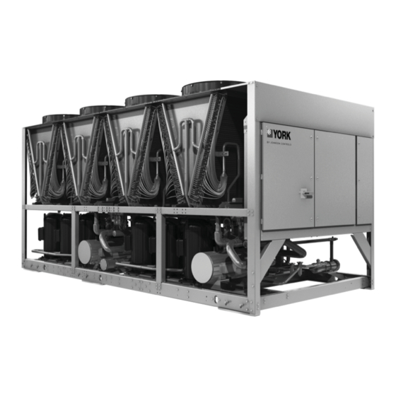
- Page 1 FORM 150.68-EG1 (0212) Model YLPA Air-to-Liquid Reversible Scroll Heat Pumps Style A Cooling Capacities: 115 Tons to 170 Tons Cooling Capacities: 400 kW to 600 kW Heating Capacities:1390 MBH to 2040 MBH Heating Capacities: 400 kW to 600 kW 60Hz...
-
Page 2: Table Of Contents
Heating Mode Capacity (kW) (1) At 54/44°F chilled water temperatures and 95°F ambient. (2) At 104/113°F hot water temperatures and 44°F ambient. NOMENCLATURE YLPA 0115S E 40XBA 1 2 3 4 5 6 7 8 11 12 13 14 15... -
Page 3: Product Description
Water connection to the heat exchanger is via victaulic grooved connections. Victaulic groove to fl ange YLPA heat pumps are designed in accordance with NFPA converters are available as an option 70 (National Electric Code), ASHRAE/ANSI 15 Safety... -
Page 4: Microcomputer Control Center
FORM 150.68-EG1 (0212) Microcomputer Control Center The control panel includes: Displayed Data: • Leaving liquid temperature • A Liquid Crystal Display (two display lines of twenty characters per line) with Light Emitting Diode • Air coil defrost temperatures backlighting for easy viewing •... -
Page 5: Accessories And Options
FORM 150.68-EG1 (0212) Accessories and Options FLOW SWITCH - The fl ow switch or its equivalent must be furnished with each unit. 150 psig (10.5 bar) DWP - For standard units. Johnson Controls model F61MG-1C Vapor-proof SPDT, NEMA 3R switch (150 PSIG [10.5 bar] DWP), -20°F to 250°F (-29°C to 121°C), with 1”... -
Page 6: Refrigerant Flow Block Diagrams
FORM 150.68-EG1 (0212) Refrigerant Flow Block Diagrams COOLING MODE Low pressure liquid refrigerant enters the heat exchanger and is evaporated and superheated by the heat energy absorbed from the chilled liquid. Low pressure vapor enters the compressor, via the four-way reversing valve and accumulator, where pressure and superheat are increased. -
Page 7: Component Location
FORM 150.68-EG1 (0212) Component Location 1 Power Panel 5 Heat Exchanger 2 Non-Fused Disconnect Switch 6 Suction Accumulator 3 Control Panel 7 Ambient Coils 4 Compressors 8 Fans WEIGHTS AND WEIGHT DISTRIBUTION The weights and weight distribution are given below: Weight (lbs) Point Weight (lbs) Model... -
Page 8: Application Data
fl ues and other sources of page for location clearances. airborne chemicals that could attack the condenser coils and steel parts of the unit. Dim. YLPA (in) 0115SE 0145SE 0170SE If located in an area accessible to unauthorized persons, Arrangement steps must be taken to prevent access to the unit by means of a protective fence. - Page 9 FORM 150.68-EG1 (0212) JOHNSON CONTROLS...
- Page 10 FORM 150.68-EG1 (0212) Application Data - continued INSTALLATION OF VIBRATION ISOLATORS The heat exchanger(s) must not be exposed to fl ushing velocities or debris released during flushing. It is An optional set of vibration isolators can be supplied loose recommended that a suitably sized by-pass and valve with each unit.
- Page 11 FORM 150.68-EG1 (0212) PIPEWORK ARRANGEMENT treatment specialist be consulted to determine whether the proposed water composition will not affect the heat The following are suggested pipework arrangements for exchanger materials of carbon steel and copper. The pH single unit installations. For multiple unit installations, value of the water fl...
- Page 12 The YORK voltage free contacts are rated at 125 All electrical wiring should be carried out in accordance with local regulations. Route properly sized cables to the cable entries in the bottom of the power panel.
- Page 13 FORM 150.68-EG1 (0212) Alarm Contacts Fan Full Speed Inhibit Each refrigerant system has a voltage-free normally open To reduce unit noise the fans can be limited to run at a contact that will close when control power is applied to maximum step of all fans in star (reduced speed) i.e.
-
Page 14: Connection Diagram
ELECTRONIC SECTION POWER SECTION POWER SECTION 23 24 25 26 27 28 29 30 31 32 33 34 13 14 13 15 13 20 13 21 13 50 13 51 A+ A- REMOTE EMERGENCY STOP DEVICE YLPA CUSTOMER WIRING JOHNSON CONTROLS... -
Page 15: Water Pressure Drop
FORM 150.68-EG1 (0212) Water Pressure Drop Refrigerant to Water Heat Exchanger Pressure Drop Graph 0115SE 0145SE 0170SE 1000 Flow Rate (gpm) JOHNSON CONTROLS... -
Page 16: Ratings
Rated in accordance with AHRI Standard 550/590 based on sea level altitude, evaporator fouling factor of 0.0001°F-ft²h/ Btu, evaporator temperature drop of 10°F, and 2 pass evaporator confi guration. AIR TEMPERATURE ON - CONDENSER (°F) LCWT YLPA IPLV (°F) MODEL... - Page 17 PERFORMANCE DATA - PART LOAD Rated in accordance with AHRI Standard 550/590 based on sea level altitude, evaporator fouling factor of 0.0001°F-ft²h/ Btu, evaporator temperature drop of 10°F, and 2 pass evaporator confi guration. YLPA 0115 SE YLPA 0115 SE % Displ.
- Page 18 Rated in accordance with AHRI Standard 550/590 based on sea level altitude, evaporator fouling factor of 0.0001°F-ft²h/ Btu, evaporator temperature drop of 10°F, and 2 pass evaporator confi guration. AIR TEMPERATURE ON - CONDENSER (°F) LHWT YLPA (°F) MODEL COMP...
-
Page 19: Technical Data
FORM 150.68-EG1 (0212) Technical Data OPERATING LIMTATIONS 0115SE 0145SE 0170SE YLPA Min. Max. Min. Max. Min. Max. 39 to 59 Liquid Outlet Temperature (Water) °F Cooling 6 to 15 Liquid Outlet Temperature Range (T) °F Mode Air Temperature - Standard Unit °F... - Page 20 Fan LRA (each fan) Evaporator Heater Supply V - Ø - Hz 115 - 1 60 115 - 1 60 115 - 1 60 Evaporator Heater Load SOUND DATA Sound Power YLPA Model dB(A) YLPA0115SE Base Unit YLPA0145SE YLPA0170SE YLPA0115SE incl. Acoustic YLPA0145SE...
-
Page 21: Dimensions
FORM 150.68-EG1 (0212) Dimensions DIMENSIONS - YLPA 0115SE JOHNSON CONTROLS... - Page 22 FORM 150.68-EG1 (0212) Dimensions - continued DIMENSIONS - YLPA 0145SE JOHNSON CONTROLS...
- Page 23 FORM 150.68-EG1 (0212) DIMENSIONS - YLPA 0170SE JOHNSON CONTROLS...
- Page 24 www.johnsoncontrols.com FORM 150 68 EG1 (0212) Subject to change without notice. Revision 0 ALL RIGHTS RESERVED...
Need help?
Do you have a question about the YLPA and is the answer not in the manual?
Questions and answers