Table of Contents
Advertisement
73-7921-250
2/14
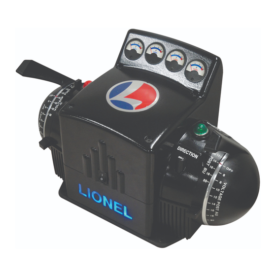
ZW-L Transformer
ZW-L Transformer
Owner's Manual
Owner's Manual
CAUTI O N—
ELECTRI C ALLY-OPERATED PRODUCT:
NOT RECOMMENDED FOR CHI L DREN UNDER FOURTEEN YEARS OF AGE. AS
WI T H ALL ELECTRI C PRODUCTS, PRECAUTI O NS SHOULD BE OBSERVED DUR-
I N G HANDLI N G AND USE TO PREVENT ELECTRI C SHOCK. TRANSFORMER
RATINGS—I N PUT: 120 VAC; 50/60 HZ. AC OUTPUT: 18 V; 620 VA.
Advertisement
Table of Contents

Related Manuals for Lionel ZW-L Transformer


Summary of Contents for Lionel ZW-L Transformer
- Page 1 73-7921-250 2/14 ZW-L Transformer ZW-L Transformer Owner’s Manual Owner’s Manual CAUTI O N— ELECTRI C ALLY-OPERATED PRODUCT: NOT RECOMMENDED FOR CHI L DREN UNDER FOURTEEN YEARS OF AGE. AS WI T H ALL ELECTRI C PRODUCTS, PRECAUTI O NS SHOULD BE OBSERVED DUR- I N G HANDLI N G AND USE TO PREVENT ELECTRI C SHOCK.
- Page 2 Congratulations! ongratulations on your purchase of the Lionel ZW-L Transformer! True to the signature design elements of its iconic predecessor, the ZW-L Transformer features four-handle operation so you can run up to four different trains or accessories at the same time.
-
Page 3: Table Of Contents
Command Control operation Operating Conventional locomotives in the Command Control environment using a CAB-2/CAB-1 Remote Controller Connecting the Command Base to the ZW-L Transformer Operating your layout in the Command Control environment using a single output LEGACY Control System operations... -
Page 4: Safety Information
Lionel Service Center. In the event that such a condition exists, the transformer should not be used until it has been properly repaired. • The ZW-L Transformer is intended to be used indoors. Do not use this device outdoors or if water is present. Serious or fatal injuries may result. -
Page 5: Protecting Your Layout From Overloads
For Command operation press RESET or enter AUX1, 0 on the CAB-2/CAB-1 for that output. The circuit breakers on the ZW-L Transformer are designed as a fail-safe for the electronic over-current protection. Because most problems will be protected by and corrected during fold-back mode operation (described in the previous section), circuit breakers should be tripped infrequently. -
Page 6: Features Overview
Features overview Operating controls he ZW-L Transformer's main operating controls are highlighted in this section. Refer to Figure 2 on page 7 for the location of these features. THROTTLE LEVERS (all outputs) Each throttle lever controls the voltage to each of the corresponding outputs. Push the levers for- ward to increase track power. -
Page 7: Operating Controls
Operating controls (continued) METERS The ZW-L Transformer features two voltage meters. See Figure 2. The right-hand meter reads the voltage on Outputs A-U and B-U (default reading is Output A-U); the left-hand meter reads the volt- age on Outputs C-U and D-U (default reading is Output D-U). -
Page 8: Transformer Controls
COMMAND/CONVENTIONAL (CMD/CONV) SWITCH For Conventional operation, set the COMMAND/CONVENTIONAL switch to CONV. To operate the ZW-L Transformer with a CAB-2 or CAB-1 Remote Controller, set the switch to CMD. RUN/PROGRAM (RUN/PGM) SWITCH For operation in the Command environment, slide the switch to the PGM position to assign a unique TR or ENG ID# to each output;... -
Page 9: Transformer Controls
Features overview Transformer controls (continued) Command/ 1 Channel/4 Channel Conventional switch switch Run/Program switch Internal cooling fan Circuit Circuit breakers breakers Command Base binding post A-U Binding C-U Binding D-U Binding B-U Binding posts (Output A) posts (Output D) posts (Output C) posts (Output B) Figure 3. -
Page 10: Zw-L Transformer Set-Up
Lockon upward so that the clip snaps onto the center rail. Next, attach a wire to either the A or D terminal on the ZW-L Transformer and connect it to the No. 1 (center rail) terminal on the Lockon. -
Page 11: Connecting The Zw-L Transformer To Your Track
ZW-L Transformer set-up Connecting the ZW-L Transformer to your track (continued) Binding posts on the back Lionel Lockon of the ZW-L Transformer (available separately) FasTrack Terminal section (available separately) Figure 4. Track connections... -
Page 12: Supplying Power Across A Large Layout
Figure 5. For ease of operation, the ZW-L Transformer can be placed in single handle mode (see the pro- cedure on pages 15 and 18). Four separate loops can then be powered-up at the same time using Throttle A. -
Page 13: Connecting The Zw-L Transformer To Your Accessories
ZW-L Transformer set-up Connecting the ZW-L Transformer to your accessories hile output terminals A-U and D-U are designed for train control, B-U and C-U are intended to supply power for lights, switches, and accessory equipment. For best results, use spadelugs (U-shaped connectors) on all ZW-L connections and no more than two wires on each terminal. -
Page 14: Conventional Operation
Operating your trains in the Conventional environment fter the ZW-L Transformer is connected to the track or your accessory, slide the CMD/CONV switch to the CONV position, the 1-CH/4-CH switch to the 4-CH position, and then set the power switch to the On position. -
Page 15: Operating Your Layout With A Single Throttle Lever (Throttle A)
Conventional operations Operating your layout with a single throttle lever (Throttle A) o control the voltage to all four outputs using a single throttle lever (Throttle A), set the power switch to the Off position (or unplug the Transformer), slide the 1-CH/4-CH switch to the 1-CH position, and then set the power switch to the On position. -
Page 16: Command Control Operation
Operating Conventional locomotives in the Command Control environment using a CAB-2/CAB-1 Remote Controller he ZW-L Transformer can also be controlled remotely in the Command Control environment with the addition of a Command Base and a CAB-2 or CAB-1 Remote controller (both available separately). -
Page 17: Connecting The Command Base To The Zw-L Transformer
Command Base (available separately) communication wire to the Command Base binding post on the back of the ZW-L Transformer. See Figure 6. Alternately, you may connect the Command Base communication wire directly to the outside rail. -
Page 18: Operating Your Layout In The Command Control Environment Using A Single Output
Command Control operations Operating your layout in the Command Control environment using a single output o control the voltage to all four outputs using a single throttle, set the power switch to the Off position, slide the 1-CH/4-CH switch to the 1-CH position and then set the power switch to the On position. -
Page 19: Legacy Control System Operations
Note! ID#s with LEGACY system Version 1.3 or lower will result in unexpected operation. Press SET. The LIONEL light on the front of the transformer will flash to indicate that the ID# has been set. Slide the PROG/RUN switch back to the RUN position. Output A-U has now been assigned the ID# you selected and Outputs B-U, C-U and D-U have been automatically assigned the next three consecutive numbers. -
Page 20: Setting The Device Type And Control Mode For Each Zw-L Output
LEGACY Control System operations Setting the device type and control mode for each ZW-L output f the ZW-L has been assigned an ENG ID# you will need to select a device type and control mode for each of the ZW-L outputs so the CAB-2 knows how to operate the transformer. You may also give each ZW-L output a name and a road number. -
Page 21: Legacy Cab-2 Remote Controller Commands
LEGACY Control System operations LEGACY CAB-2 Remote Controller Commands Warning Sound Controller Push up to trigger the bell on equipped locomotives. Pull down to trigger the whistle on equipped locomotives. Train Brake Slider Adjust to set the limit for the maximum voltage from the output. -
Page 22: Trainmaster Command Control Operations
Enter the unique ID#. You may select any ENG ID# from 1 to 95 or any TR ID# from 1 to 6. Press SET. The LIONEL light on the front of the transformer will flash to indicate that the ID# has been set. -
Page 23: Cab-1 Remote Controller Commands
TrainMaster Command Control operations CAB-1 Remote Controller commands Fires the rear ElectroCoupler on Command locomotives and select Conventional locomotives. Fires the front ElectroCoupler on Command locomotives and select Conventional locomotives. The AUX1, 0 sequence sets the output voltage to zero and resets an overload shutdown. Increases the output voltage with a clockwise rotation up to the limit set by the handle on the ZW-L. -
Page 24: Non-Lionel Locomotive Operation
Running non-Lionel locomotives with your CAB-2/CAB-1 Remote Controller our ZW-L Transformer was designed to be compatible with all locomotives operating on AC volt- age from 0 to 18 volts. No modification of the locomotive is required. If you experience erratic operation of some non-Lionel locomotives (such as random horn and bell sounds), placing a lighted car on the track or connecting an accessory to track power should elimi- nate the problem. -
Page 25: Maintenance And Service
Maintenance and service Troubleshooting No lights or operation Be sure that the ZW-L Transformer is plugged into a working outlet and that the power switch is in the On position. Circuit breaker trips immediately when power is applied Recheck the wiring, look for short circuits. Disconnect all wiring and reconnect them one at a time until the defective circuit is found. - Page 26 Output(s) have been shut down because of an overload. Check the output connection for short cir- cuits, and then reset the output. See page 5. We invite you to visit www.lionel.com and click on the Customer Services tab to order parts and access other important service information.
-
Page 27: Fcc Statement
Maintenance and service FCC Statement Warning: Changes or modifications to this unit not expressly approved by the party responsible for compliance could void the user authority to operate the equipment. Notes: This equipment has been tested and found to comply with the limits for a Class B digital device, pursuant to Part 15 of the FCC Rules. -
Page 28: Lionel Limited Warranty Policy & Service
(or copy) from an Authorized Lionel Retailer*, will at the discretion of Lionel LLC, be repaired or replaced, without charge for parts or labor. In the event the defective product cannot be repaired, and a suitable replacement is not available, Lionel will offer to replace the product with a comparable model (determined by Lionel LLC), if available.
Need help?
Do you have a question about the ZW-L Transformer and is the answer not in the manual?
Questions and answers