Siemens S7-1200 Operating Instructions Manual
Hubs & controllers telecontrol/lte
Hide thumbs
Also See for S7-1200:
- System manual (1028 pages) ,
- Operating instructions manual (132 pages) ,
- Programming manualline (74 pages)
Table of Contents
Advertisement
CP 1243-7 LTE
SIMATIC NET
S7-1200 - TeleControl
CP 1243-7 LTE
Operating Instructions
CP 1243-7 LTE-EU
01/2015
C79000-G8976-C381-01
___________________
Preface
___________________
Application and properties
___________________
LEDs and connectors
___________________
Installation, connecting up,
commissioning
___________________
Configuration and operation
___________________
Programming the
program blocks
___________________
Diagnostics and upkeep
___________________
Technical specifications
___________________
Dimension drawings
___________________
Approvals
___________________
Accessories
___________________
Documentation references
1
2
3
4
5
6
7
A
B
C
D
Advertisement
Table of Contents

Related Manuals for Siemens S7-1200


Summary of Contents for Siemens S7-1200
- Page 1 CP 1243-7 LTE Preface ___________________ Application and properties ___________________ SIMATIC NET LEDs and connectors ___________________ Installation, connecting up, commissioning S7-1200 - TeleControl CP 1243-7 LTE ___________________ Configuration and operation ___________________ Programming the program blocks Operating Instructions ___________________ Diagnostics and upkeep...
- Page 2 Note the following: WARNING Siemens products may only be used for the applications described in the catalog and in the relevant technical documentation. If products and components from other manufacturers are used, these must be recommended or approved by Siemens. Proper transport, storage, installation, assembly, commissioning, operation and maintenance are required to ensure that the products operate safely and without any problems.
-
Page 3: Preface
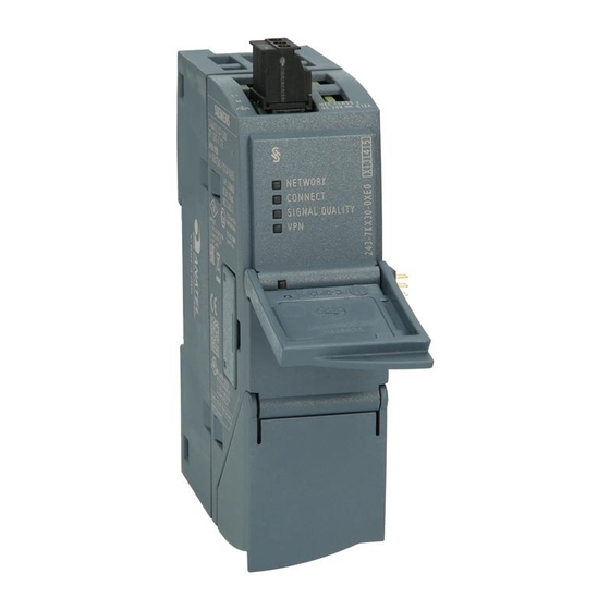
● CP1243-7 LTE-EU Article number 6GK7 243-7KX30-0XE0 Hardware product version 1 Firmware version V2.1 The device is the communications processor for connecting the SIMATIC S7-1200 via LTE, UMTS or GSM mobile wireless networks. Figure 1 CP 1243-7 LTE Behind the top hinged cover of the module housing, next to the article number you will see the hardware product version printed as a placeholder "X"... - Page 4 Replaced manual issue None Current manual release on the Internet You will also find the current version of this manual on the Internet pages of Siemens Industry Online Support under the following entry ID: 102255422 (http://support.automation.siemens.com/WW/view/en/102255422) > > Entry list > Entry type "Manuals"...
- Page 5 Siemens recommends strongly that you regularly check for product updates. For the secure operation of Siemens products and solutions, it is necessary to take suitable preventive action (e.g. cell protection concept) and integrate each component into a holistic, state-of-the-art industrial security concept.
- Page 6 Preface Firmware The firmware is signed and encrypted. This ensures that only firmware created by Siemens can be downloaded to the device. Training, Service & Support You will find information on Training, Service & Support in the multi--language document "DC_support_99.pdf" on the data medium supplied with the documentation.
-
Page 7: Table Of Contents
Table of contents Preface ..............................3 Application and properties ........................11 Connecting the S7-1200 to a mobile wireless network ............11 Communications services ....................... 13 Other services and properties ....................14 Performance data and configuration limits ................17 Requirements for operation ....................19 Configuration examples ...................... - Page 8 Table of contents 4.13 Security functions ........................58 4.13.1 VPN ............................58 4.13.1.1 VPN (Virtual Private Network) ....................58 4.13.1.2 Addressing the CP when using VPN ..................59 4.13.1.3 Creating a VPN tunnel for S7 communication between stations ........... 59 4.13.1.4 VPN communication with SOFTNET Security Client (engineering station) ......
- Page 9 Table of contents Dimension drawings ..........................117 Approvals ............................119 Accessories ............................125 Antenna ..........................125 TS Gateway .......................... 125 Documentation references ........................129 Index..............................131 CP 1243-7 LTE Operating Instructions, 01/2015, C79000-G8976-C381-01...
- Page 10 Table of contents CP 1243-7 LTE Operating Instructions, 01/2015, C79000-G8976-C381-01...
-
Page 11: Application And Properties
Connecting the S7-1200 to a mobile wireless network The CP is intended for use in industrial environments. Type of communication, mobile wireless standards, frequency bands Using the CP, the S7-1200 SIMATIC controller can be connected to mobile wireless networks of the following standards: ● CP 1243-7 LTE-EU The CP supports the following mobile wireless standards: –... - Page 12 Application and properties 1.1 Connecting the S7-1200 to a mobile wireless network IP-based WAN communication via mobile wireless networks The CP allows WAN communication from remote stations with a master station, communication between stations via a master station (inter-station communication) and direct communication between stations.
-
Page 13: Communications Services
CP. ● Communication with a control center Remote S7-1200 stations communicate via the mobile wireless network and the Internet with a telecontrol server in the master station. The telecontrol server communicates with a higher-level control system using the integrated OPC server function. -
Page 14: Other Services And Properties
TeleService is possible if the online functions are enabled in the configuration of the CP. A TeleService connection can be established between an engineering station (PC with STEP 7) and a remote S7-1200 station via the mobile wireless network and the Internet. You can use the TeleService connection for the following purposes: ●... - Page 15 Application and properties 1.3 Other services and properties ● Time-of-day synchronization – When telecontrol communication is enabled, the CP obtains its local time of day as UTC time from the partner (TCSB). The time of day can be read from the CPU. The mechanisms are described in the STEP 7 information system.
- Page 16 Application and properties 1.3 Other services and properties Security functions of the telecontrol protocol The CP supports the following Security functions: ● Encrypted telecontrol communication You configure the interval of the key exchange between the CPU and telecontrol server in STEP 7 in the parameter group "Ethernet interface (X1) >...
-
Page 17: Performance Data And Configuration Limits
CPU. As a result of using the CP, as a Security module, the following additional Security functions are accessible to the S7-1200 station on the interface to the external network: ● Firewall – IP firewall with stateful packet inspection (layer 3 and 4) –... - Page 18 Application and properties 1.4 Performance data and configuration limits Number of simultaneous TeleService connections ● Max. 1 TeleService connection Number of simultaneous connections for S7 communication and Open User Communication A maximum total of 14 connection resources for S7 communication and Open User Communication The maximum number can be divided up as required into: ●...
-
Page 19: Requirements For Operation
● Maximum 128 rules with limitation of the transmission speed ("Bandwidth limitation") Requirements for operation Hardware requirements Apart from the CP in the remote S7-1200, the following hardware is also required: ● A CPU with firmware version as of V4.1 ● An external antenna for the CP Use only antennas from the accessories program for the CP, refer to the appendix Antenna (Page 125). - Page 20 Application and properties 1.5 Requirements for operation Configuration software To configure the module, the following configuration tool is required: STEP 7 Basic V13 + SP1 Program blocks for Open User Communication and S7 communication For Open User Communication and S7 communication, program blocks are required, see section Communications services (Page 13).
-
Page 21: Configuration Examples
Figure 1-1 Sending messages by SMS from an S7-1200 station The CP can send SMS messages to a mobile phone or a configured S7-1200 station and receive from these nodes. The mechanisms for this are as follows: ● SMS messages generated and sent as the result of an event. - Page 22 You will find information on the blocks in the section Program blocks for OUC (Page 91), you will find the description of the programming in the STEP 7 information system. Telecontrol by a control center Figure 1-2 Communication between S7-1200 stations and a control center CP 1243-7 LTE Operating Instructions, 01/2015, C79000-G8976-C381-01...
- Page 23 Figure 1-3 Direct communication between two S7-1200 stations In this configuration, two SIMATIC S7-1200 stations communicate directly with each other using the CP via the mobile wireless network. Each CP has a fixed IP address. The relevant service of the network provider must allow this.
- Page 24 Application and properties 1.6 Configuration examples TeleService with telecontrol server The connection runs via the telecontrol server. ● The engineering station and telecontrol server are connected via the Intranet (LAN) or Internet. ● The telecontrol server and remote station are connected via the Internet and via the mobile wireless network.
- Page 25 Application and properties 1.6 Configuration examples TeleService with TeleService gateway (via LAN) The connection between the engineering station and S7 station is via the TeleService gateway. The engineering station is connected to the TeleService gateway via LAN. Figure 1-5 TeleService via the mobile wireless network with TeleService gateway - connection via CP 1243-7 LTE Operating Instructions, 01/2015, C79000-G8976-C381-01...
- Page 26 Application and properties 1.6 Configuration examples TeleService with TeleService gateway (via the Internet) The connection between the engineering station and S7 station is via the TeleService gateway. The engineering station is connected to the TeleService gateway via the Internet. Figure 1-6 TeleService via the mobile wireless network with TeleService gateway - connection via the Internet CP 1243-7 LTE...
-
Page 27: Leds And Connectors
LEDs and connectors Opening the housing Location of the display elements and the electrical connectors The LEDs for the detailed display of the module statuses are located behind the upper cover of the module housing. The socket for the power supply is located on the top of the module. The connector for the external antenna is located on the bottom of the module. -
Page 28: Leds
LEDs and connectors 2.2 LEDs LEDs LEDs of the module The CP has the following LEDs for displaying the status: ● "DIAG" LED on the front panel The "DIAG" LED that is always visible shows the basic statuses of the module. ●... - Page 29 LEDs and connectors 2.2 LEDs DIAG NETWORK CONNECT SIGNAL Meaning QUALITY (red / green) (red / green) (green) (green) (yellow / green) Display of the basic statuses of the module Power OFF Startup Errors: Invalid CP configuration • flashing red CP type does not match the configuration •...
- Page 30 LEDs and connectors 2.2 LEDs DIAG NETWORK CONNECT SIGNAL Meaning QUALITY (red / green) (red / green) (green) (green) (yellow / green) Quality of the mobile wireless connection Good network (-73 ... ≥ -51 dBm) Medium strength network (-89 ... -74 dBm) Weak network (-109 ...
-
Page 31: Electrical Connectors
LEDs and connectors 2.3 Electrical connectors Electrical connectors 2.3.1 Power supply Power supply The 3-pin socket for the external 24 V DC power supply is located on the top of the module. The matching plug ships with the product. You will find the pin assignment of the socket in section Pin assignment of the socket for the external power supply (Page 116). -
Page 32: Wireless Interface
LEDs and connectors 2.3 Electrical connectors 2.3.2 Wireless interface Wireless interface for the mobile wireless network An extra antenna is required for communication in the mobile wireless network. This is connected via the SMA socket of the CP. The SMA socket is located behind the lower front cover of the CP. -
Page 33: Installation, Connecting Up, Commissioning
Installation, connecting up, commissioning Important notes on using the device Safety notices on the use of the device Note the following safety notices when setting up and operating the device and during all associated work such as installation, connecting up or replacing the device. Overvoltage protection NOTICE Protection of the external power supply... -
Page 34: Notices On Use In Hazardous Areas
Installation, connecting up, commissioning 3.1 Important notes on using the device 3.1.1 Notices on use in hazardous areas WARNING EXPLOSION HAZARD DO NOT OPEN WHEN ENERGIZED. WARNING The equipment is designed for operation with Safety Extra-Low Voltage (SELV) by a Limited Power Source (LPS). -
Page 35: General Notices On Use In Hazardous Areas According To Atex
Installation, connecting up, commissioning 3.1 Important notes on using the device 3.1.2 General notices on use in hazardous areas according to ATEX WARNING Requirements for the cabinet/enclosure To comply with EU Directive 94/9 (ATEX95), the enclosure or cabinet must meet the requirements of at least IP54 in compliance with EN 60529. -
Page 36: Installing The Cp And Commissioning
Read the system manual "S7-1200 Programmable Controller" Prior to installation, connecting up and commissioning, read the relevant sections in the system manual "S7-1200 Programmable Controller", refer to the documentation in the Appendix. When installing and connecting up, keep to the procedures described in the system manual "S7-1200 Programmable Controller". - Page 37 Installation, connecting up, commissioning 3.2 Installing the CP and commissioning Prior to installation, insert the SIM card in the CP. Step Execution Notes and explanations Turn off the power supply to the station. Release the slide for the SIM card on the bottom of the CP behind the lower cover by gently pressing the release pin.
- Page 38 Installation, connecting up, commissioning 3.2 Installing the CP and commissioning Dimensions for installation Figure 3-1 Dimensions for installation of the S7-1200 Table 3- 1 Dimensions for installation (mm) S7-1200 devices Width A Width B * CPU 1211C, CPU 1212C 90 mm...
- Page 39 Vertical installation of the rack Note Connection with power off Only wire up the S7-1200 with the power turned off. Note Power supply from the power outputs of the CPU The external power supply of the CP must be supplied via the power outputs of the CPU.
- Page 40 Installation, connecting up, commissioning 3.2 Installing the CP and commissioning Note Turning off the station when plugging/pulling the CP Do not only turn off the power supply to the CP. Always turn off the power supply for the entire station. Table 3- 2 Procedure for installation and connecting up Step...
-
Page 41: Configuration And Operation
(Page 19). You can configure a maximum of three CMs/CPs per station. If you insert several CPs in an S7-1200, you can, for example, establish redundant communications paths. Configuring communication with the CPU (data point configuration) CP communication is not programmed using program blocks but configured using data points. -
Page 42: Information Required For Configuration
Configuration and operation 4.3 Information required for configuration Overview of the configuration steps in STEP 7 Notes: ● No Ethernet network needs to be created for the communication via the mobile wireless network. ● A telecontrol server or a TeleService- gateway cannot be configured in STEP 7. Follow the steps below when configuring: 1. - Page 43 Configuration and operation 4.3 Information required for configuration General information The following information is required for the STEP 7 configuration of the CP: ● Own phone number of the CP (required for TeleService) ● Authorized phone numbers Phone numbers of the nodes that are allowed to send an SMS to the CP. ●...
- Page 44 Configuration and operation 4.3 Information required for configuration Information required for telecontrol communication The following information is required for the STEP 7 configuration of the CP: ● Address of the telecontrol server – IP address – Name of the telecontrol server that can be resolved by DNS –...
-
Page 45: Configuration Of The Teleservice Access
Configuration and operation 4.4 Configuration of the TeleService access Address and authentication information for communication with TCSB The following information is required for the STEP 7 configuration of the CP for communication with TCSB: ● Parameters in the "Partner stations" parameter group –... - Page 46 Configuration and operation 4.4 Configuration of the TeleService access Global Security settings of the project 1. Open the following page in the project tree: Global security settings > User management 2. Role Open the "Roles" tab The two tables "Roles" and "Rights of the role" become visible. If necessary open the "Roles view"...
-
Page 47: Configuring Data Points And Messages
Configuration and operation 4.5 Configuring data points and messages Configuring data points and messages Data point-related communication with the CPU No program blocks need to be programmed for the CP to transfer user data between the station and communications partner. The data areas in the memory of the CPU intended for communication with the partner are configured data point-related on the CP. -
Page 48: Datapoint Types
Configuration and operation 4.6 Datapoint types Configuring the data points and messages in STEP 7 You configure the data points in STEP 7 in the editor for the data point and message configuration. You can find this using the project tree: Project >... - Page 49 Configuration and operation 4.6 Datapoint types Supported data point types of the CP Table 4- 1 Supported data point types and compatible S7 data types Format (memory re- Data point type S7 data types Address area quirements) Digital input BOOL I, Q, M, DB Digital output BOOL...
-
Page 50: Cpu Scan Cycle
Configuration and operation 4.7 CPU scan cycle CPU scan cycle Priority in the scan cycle The cyclic updating of the values of input data points of the CP by reading the current values of the assigned PLC tags on the CPU can be prioritized. Less important input data points do not need to be read in every CPU scan cycle. -
Page 51: Process Image, Type Of Transmission, Event Classes, Triggers
Configuration and operation 4.8 Process image, type of transmission, event classes, triggers Process image, type of transmission, event classes, triggers The image memory, the process image of the CP The image memory is the process image of the CP. All the current values of the configured data points are stored in the image memory. - Page 52 Configuration and operation 4.8 Process image, type of transmission, event classes, triggers Configuration of data points as events Data points are configured as a static value or as an event using the "Type of transmission" parameter (see below): ● No event (static value) The values of data points that are not configured as an event ("Transfer after call") are entered in the image memory of the CP and transferred to the communications partner when it requests this value.
- Page 53 Configuration and operation 4.8 Process image, type of transmission, event classes, triggers Trigger Various trigger types are available for starting event-driven transfer: ● Threshold value trigger The value of the data point is transferred when this reaches a certain threshold. The threshold is calculated as the difference compared with the last stored value, refer to the section Threshold value trigger (Page 78).
-
Page 54: Status Ids Of Data Points
Configuration and operation 4.9 Status IDs of data points Status IDs of data points Status IDs of data points The status identifiers of the data points listed in the following tables are transferred along with the value in each frame to the communications partner. They can be evaluated by the communications partner. -
Page 55: Acknowledgment
Configuration and operation 4.11 Acknowledgment 4.11 Acknowledgment Acknowledgment of frames The receipt of a frame is monitored and acknowledged in different ways. The mechanisms differ depending on the type of communication: ● Telecontrol communication Frames received from TCSB are acknowledged immediately by the CP. Frames sent by the CP are acknowledged by TCSB. - Page 56 Configuration and operation 4.12 Calling a TeleService connection Settings for establishing a TeleService connection In the dialog "Establish mobile wireless remote connection", enter the previously configured data under the following headings: ● Telecontrol server / TeleService gateway... ● Selection whether the TeleService switching station is located on the PC of the engineering station or in the network or can be reached via the Internet.
- Page 57 Configuration and operation 4.12 Calling a TeleService connection Note Canceling a TeleService connection when calling online dialogs An existing TeleService connection is canceled when you attempt to access an additional station or a node. When there is an existing TeleService connection, do not select any of the menu commands "Go online", "Online &...
-
Page 58: Security Functions
Configuration and operation 4.13 Security functions 4.13 Security functions Note the range and application of the security functions of the CP, refer to the section Other services and properties (Page 14). 4.13.1 4.13.1.1 VPN (Virtual Private Network) VPN tunnel Virtual Private Network (VPN) is a technology for secure transportation of confidential data in public IP networks, for example the Internet. -
Page 59: Addressing The Cp When Using Vpn
Configuration and operation 4.13 Security functions Cell protection concept With Industrial Ethernet Security, individual devices or network segments of an Ethernet network can be protected: ● Access to individual devices and network segments protected by security modules is allowed. ● Secure connections via non-secure network structures becomes possible. Due to the combination of different security measures such as firewall, NAT/NAPT routers and VPN via IPsec tunnels, security modules protect against the following: ●... - Page 60 Configuration and operation 4.13 Security functions Procedure To create a VPN tunnel, you need to work through the following steps: 1. Creating a security user If the security user has already been created: Log on as a user. 2. Select the "Activate security features" check box 3.
- Page 61 Configuration and operation 4.13 Security functions Note Current date and current time on the CP for VPN connections Normally, to establish a VPN connection and the associated recognition of the certificates to be exchanged, the current date and the current time are required on both stations. The establishment of a VPN connection to an engineering station that is also the telecontrol server at the same time (TCSB installed), runs as follows along with the time of day synchronization of the CP:...
-
Page 62: Vpn Communication With Softnet Security Client (Engineering Station)
Configuration and operation 4.13 Security functions 4.13.1.4 VPN communication with SOFTNET Security Client (engineering station) Setting up VPN tunnel communication between the SOFTNET Security Client and CP has essentially same requirements and procedure as described in the section Creating a VPN tunnel for S7 communication between stations (Page 59). -
Page 63: Cp As Passive Subscriber Of Vpn Connections
Configuration and operation 4.13 Security functions 4.13.1.6 CP as passive subscriber of VPN connections Setting permission for VPN connection establishment with passive subscribers If the CP is connected to another VPN subscriber via a gateway, you need to set the permission for VPN connection establishment to "Responder". -
Page 64: Filtering Of The System Events
Configuration and operation 4.14 Time-of-day synchronization 4.13.3 Filtering of the system events Communications problems if the value for system events is set too high If the value for filtering the system events is set too high, you may not be able to achieve the maximum performance for the communication. - Page 65 Configuration and operation 4.14 Time-of-day synchronization Configuration Depending on the configured communication types and security functions, time-of-day synchronization is configured differently: ● Telecontrol communication enabled With telecontrol communication enabled, the time of day of the CP is synchronized automatically by the TCSB computer. –...
-
Page 66: Step 7 Configuration Of Individual Parameters
Configuration and operation 4.15 STEP 7 configuration of individual parameters 4.15 STEP 7 configuration of individual parameters Below, you will find information on the configuration of individual functions grouped according to parameter groups in STEP 7. Note Information in STEP 7 and in the manual If there are discrepancies between the following descriptions and the information in STEP 7 / Professional V13, the information in this document is valid. -
Page 67: Mobile Wireless Communications Settings
Configuration and operation 4.15 STEP 7 configuration of individual parameters 4.15.2 Mobile wireless communications settings "Services and settings" parameter group In this parameter group, you configure the phone number of the CP, the PIN and the SMSC. You continue to enable the required mobile wireless services. You can enable individual mobile wireless services or all of them. - Page 68 Configuration and operation 4.15 STEP 7 configuration of individual parameters Ethernet interface (X1) > Advanced options > TCP connection monitoring The settings made here apply globally to all configured TCP connections of the CP. If telecontrol communication is enabled, this is the connection to the telecontrol server. Note the option of overwriting the general value configured here for individual communications partners, refer to the section Partner stations (Page 70).
- Page 69 Configuration and operation 4.15 STEP 7 configuration of individual parameters Note If the partner cannot be reached, connection establishment via the mobile wireless network can take several minutes. This may depend on the particular network and current network load. Depending on your contract, costs may result from each connection establishment attempt. Send timeout Time for the arrival of the acknowledgment from the telecontrol server after sending unsolicited frames.
-
Page 70: Partner Stations
Configuration and operation 4.15 STEP 7 configuration of individual parameters 4.15.4 Partner stations 4.15.4.1 Partner stations > Telecontrol server Partner stations > "Telecontrol server" ● Partner number The partner number for the telecontrol server is assigned automatically by the system if telecontrol communication is enabled. - Page 71 Configuration and operation 4.15 STEP 7 configuration of individual parameters ● TCP connection monitoring time The monitoring time is specified at a higher level for the Ethernet interface as the default for all configured TCP connections, see also section Ethernet interface (X1) (Page 67). The default value for the Ethernet interface can be adapted for the connection to the telecontrol server individually in the "Partner stations"...
-
Page 72: Partner For Inter-Station Communication
Configuration and operation 4.15 STEP 7 configuration of individual parameters Partner stations > "Telecontrol server" > "Advanced settings" ● Report partner status If the "Report partner status" function is enabled, the CP signals the status of the communication to the remote partner. –... - Page 73 Configuration and operation 4.15 STEP 7 configuration of individual parameters Slot Here, enter the slot number of the CP in the partner station. You will find the parameter in the parameter group "General" on the partner CP. Send buffer When enabled, the frames are stored in the send buffer (frame memory) of the CP if the connection is disturbed.
-
Page 74: Communication With The Cpu
Configuration and operation 4.15 STEP 7 configuration of individual parameters 4.15.5 Communication with the CPU The parameter group is displayed as soon as telecontrol communication is enabled. Communication with the CPU ● Frame memory size Here, you set the size of the send buffer for events. A maximum of 64000 events divided up equally among the communications partners can be buffered. -
Page 75: E-Mail Configuration
Configuration and operation 4.15 STEP 7 configuration of individual parameters ● 'NETWORK' LED PLC tag (data type UInt) for the status of the connection for the data service in the mobile wireless network. ● Date of last successful logon to network PLC tag (data type DTL) for the date on which the CP last logged in to the mobile wireless network. -
Page 76: Data Point Configuration
Configuration and operation 4.15 STEP 7 configuration of individual parameters Importing the certificate with encrypted transfer To be able to use encrypted transfer, you need to load the certificate of your e-mail account in the certificate manager of STEP 7. You obtain the certificate from your e-mail service provider. -
Page 77: Threshold Value Trigger And Analog Value Preprocessing
Configuration and operation 4.15 STEP 7 configuration of individual parameters Configuration of the data point index Within a CP, the indexes of the data point classes must comply with the following rules: ● Input The index of a data point of the type input must be unique throughout all data point types (digital inputs, analog inputs etc.). -
Page 78: Threshold Value Trigger
Configuration and operation 4.15 STEP 7 configuration of individual parameters Analog inputs that are configured as an event are processed on the CP in the following sequence: Sequence of analog value processing 1. Reading the data from the input area of the CPU 2. -
Page 79: Analog Value Preprocessing
Configuration and operation 4.15 STEP 7 configuration of individual parameters The method is explained based on the following example in which a threshold value of 2.0 is configured. Table 4- 3 Example of the integration calculation of a threshold value configured with 2.0 Time [s] Process value Current process... - Page 80 Configuration and operation 4.15 STEP 7 configuration of individual parameters Sequence of processing Threshold value trigger and Analog value preprocessing Note Threshold value trigger: Calculation only after "Analog value preprocessing" Note that the analog value preprocessing is performed before the check for a configured threshold value.
- Page 81 Configuration and operation 4.15 STEP 7 configuration of individual parameters Unipolar transfer With unipolar transfer, negative values are corrected to zero. This can be desirable if values from the underrange should not be transferred as real measured values. Exception: The value -32768 / 8000 for wire break of live zero inputs is transferred.
- Page 82 Configuration and operation 4.15 STEP 7 configuration of individual parameters Smoothing factor Analog values that fluctuate quickly can be evened out using the smoothing function. The smoothing factors are calculated according to the following formula as with S7 analog input modules. where = smoothed value in the current cycle = value acquired in the current cycle n...
- Page 83 Configuration and operation 4.15 STEP 7 configuration of individual parameters Set limit value 'low' / Set limit value 'high' In these two input boxes, you can set a limit value in the direction of the start of the measuring range or in the direction of the end of the measuring range. You can also evaluate the limit values, for example as the start or end of the measuring range.
- Page 84 Configuration and operation 4.15 STEP 7 configuration of individual parameters Configuration of the limit value The value to be configured as a whole decimal number therefore depends on the value range of the PLC tags and the raw value of the analog module: Division Raw value of the of PLC tags * Module output [mA]...
-
Page 85: Partner Stations: Configuring The Inter-Station Communication
Configuration and operation 4.15 STEP 7 configuration of individual parameters 4.15.7.5 Partner stations: Configuring the inter-station communication Options for specifying the communications partner Telecontrol server activated / Enable partner for inter-station communication If no partner was enabled for inter-station communication, the "Telecontrol server activated" option is selected automatically. -
Page 86: Messages
Configuring e-mails If important events occur, the CP can send e-mails. The recipient can be a PC with an Internet connection or an S7-1200. You configure the e-mails in STEP 7 in the data point and message configuration. You can find this using the project tree: Project >... - Page 87 Configuration and operation 4.15 STEP 7 configuration of individual parameters Requirements and necessary information Remember the following requirements in the CP configuration for the transfer of messages: ● Enabling telecontrol communication ("Communication types") parameter group ● Activating security functions ● Additionally for e-mails: Configuring the "E-mail configuration" parameter group To do this, you require the following information: –...
- Page 88 Configuration and operation 4.15 STEP 7 configuration of individual parameters Table 4- 5 E-mails: Meaning of the status ID output in hexadecimal format Status Meaning 0000 Transfer completed free of errors 82xx Other error message from the e-mail server Apart from the leading "8", the status corresponds to the three-digit error number of the SMTP protocol.
-
Page 89: Access To The Web Server
Access to the Web server Access to the Web server of the CPU The Web server of the S7-1200 station is located in the CPU. Via the LAN interface of the CP, you have access to the Web server of the CPU. - Page 90 Configuration and operation 4.16 Access to the Web server CP 1243-7 LTE Operating Instructions, 01/2015, C79000-G8976-C381-01...
-
Page 91: Programming The Program Blocks
Programming the program blocks Program blocks for OUC Using the program blocks for Open User Communication (OUC) The instructions (program blocks) listed below are required for direct communication between S7 stations via the mobile wireless network. In contrast to other communication types, Open User Communication does not need to be enabled in the configuration of the CP because corresponding program blocks need to be created for this. - Page 92 ● TCON_Param For transferring frames via TCP ● TADDR_Param For transferring frames via UDP ● TCON_IP_RFC For transferring frames via ISO-on-TCP (direct communication between two S7-1200 stations) ● TCON_Phone For transferring SMS messages ● TMail_V4 For transferring e-mails addressing the e-mail server using an IPv4 address ●...
-
Page 93: Programming Sms Messages Via Ouc
Programming the program blocks 5.2 Programming SMS messages via OUC Programming SMS messages via OUC Transferring e-mails / SMS messages via OUC or telecontrol communication The event-driven sending of e-mails or SMS messages using telecontrol communication is configured in STEP 7 in the message editor, refer to the section Messages (Page 86). No program blocks are required for this. - Page 94 Programming the program blocks 5.2 Programming SMS messages via OUC When creating this structure (DB of the data type "Struct"), no optimized block access can be configured. The structure should have a size of 194 bytes and the following structure to store the relevant data of the received SMS message: ●...
- Page 95 Programming the program blocks 5.2 Programming SMS messages via OUC Character set for the SMS text The CP supports the following ASCII character set (hexadecimal value and character name) for SMS message texts: ● 0x0A LF (line feed) ● 0x0D CR (carriage return) ●...
-
Page 96: Tc_Config For Changing Configuration Data Of The Cp
Programming the program blocks 5.3 TC_CONFIG for changing configuration data of the CP TC_CONFIG for changing configuration data of the CP Meaning With the program block TC_CONFIG , you can modify parameters of a the CP configured in STEP 7. The configured values are not overwritten retentively. The overwritten values remain valid until TC_CONFIG is called again or until the station starts up again (cold restart after cycling power). - Page 97 Programming the program blocks 5.3 TC_CONFIG for changing configuration data of the CP Explanation of the formal parameters The following table explains all the formal parameters for the TC_CONFIG instruction Parameter Declaration Data type Possible values Description INPUT BOOL 0, 1 The processing of the block is started and the status codes initialized on a rising edge.
- Page 98 Programming the program blocks 5.3 TC_CONFIG for changing configuration data of the CP The codes BUSY, DONE and ERROR The codes of DONE and ERROR are relevant only when BUSY = 0. BUSY DONE ERROR Meaning No job being executed You will find all other code combinations of DONE and ERROR in the following table.
-
Page 99: If_Conf: Sdt For The Configuration Data Of The Cp
Programming the program blocks 5.4 IF_CONF: SDT for the configuration data of the CP IF_CONF: SDT for the configuration data of the CP Structure of the system data type IF_CONF for the TC_CONFIG program block The CONFIG parameter of the TC_CONFIG program block references the memory area containing the configuration data of the CP to be modified. - Page 100 Programming the program blocks 5.4 IF_CONF: SDT for the configuration data of the CP Header of IF_CONF Table 5- 1 IF_CONF_Header Byte Parameter Data type Initial value Description 0 ... 1 fieldType UINT Field type: Must always be 0. 2 ... 3 fieldId UINT Field ID: Must always be 0.
- Page 101 Programming the program blocks 5.4 IF_CONF: SDT for the configuration data of the CP "APN settings" In STEP 7, the corresponding data is located in the "Mobile wireless communications settings" parameter area. Table 5- 3 IF_CONF_APN Parameter Data type Initial value Description UINT ID of the parameter field...
- Page 102 Programming the program blocks 5.4 IF_CONF: SDT for the configuration data of the CP "Telecontrol server" In STEP 7, the corresponding data is located in the "Partner stations" parameter area.". This field is only used when the telecontrol server is addressed with a name that can be resolved by DNS or when the IP address is to stored as a string.
- Page 103 Programming the program blocks 5.4 IF_CONF: SDT for the configuration data of the CP "PIN" In STEP 7, the PIN can be found in the parameter area "Mobile wireless communications settings" > "Services and settings". Table 5- 7 IF_CONF_PIN Parameter Data type Initial value Description...
- Page 104 Entry of the Public Land Mobile Network (PLMN) of the network provider consisting of Mobile Country Code (MCC) and Mobile Network Code (MNC). Example (test network of Siemens AG): 26276 TeleService access (DNS name / IP address of the server) Access data of the TeleService server (switching station).
-
Page 105: Diagnostics And Upkeep
Diagnostics and upkeep Diagnostics options The following diagnostics options are available: LEDs of the module For information on the LED displays, refer to the section LEDs (Page 28). STEP 7: The "Diagnostics" tab in the Inspector window Here, you can obtain the following information on the selected module: ●... - Page 106 Information on the time on the device Diagnostics options via the Web server of the CPU You will find details on the diagnostics options of the Web server in the S7-1200 system manual, see /1/ (Page 129). Diagnostics SMS message...
- Page 107 Diagnostics and upkeep 6.1 Diagnostics options ● Name of the current mobile wireless network ● IP address of the CP ● Signal strength of the mobile wireless network – good: Good signal quality (-73 ... -51 dBm) – medium: Medium signal quality (-89 ... -74 dBm) –...
-
Page 108: Downloading Firmware
New firmware versions of the CP If a new firmware version is available for the module, you will find this on the Internet pages of Siemens Industry Online Support under the following entry ID: 102255422 (http://support.automation.siemens.com/WW/view/en/102255422) On the Internet page, select the "Entry list" tab and the "Download" entry type. There you will find the available firmware files. - Page 109 Diagnostics and upkeep 6.2 Downloading firmware Downloading the firmware via the Web server of the CPU Follow the steps below to connect to the Web server of the CPU from the engineering station and to download the CP's new firmware file to the station. Requirements in the CPU configuration 1.
- Page 110 You will find information on downloading a certificate in the help of your Web browser and in the STEP 7 information system under the key words "HTTPS" or "Access for HTTPS (S7-1200)". 6. When the connection has changed to the secure mode HTTPS ("https://<IP address>/..."...
-
Page 111: Module Replacement
Read the system manual "S7-1200 Programmable Controller" Prior to installation, connecting up and commissioning, read the relevant sections in the system manual "S7-1200 Programmable Controller" (refer to the documentation in the Appendix). When installing and connecting up, keep to the procedures described in the system manual "S7-1200 Programmable Controller". - Page 112 Diagnostics and upkeep 6.3 Module replacement CP 1243-7 LTE Operating Instructions, 01/2015, C79000-G8976-C381-01...
-
Page 113: Technical Specifications
Power supply unit to internal 710 VDC for 1 minute circuit Current consumption (typical) From 24 VDC (external) 75 mA From the S7-1200 backplane 100 mA Effective power loss (typical) From 24 VDC (external) 1.8 W From the S7-1200 backplane 0.5 W... - Page 114 Technical specifications 7.1 General technical specifications Technical specifications Design, dimensions and weight Module format Compact module for S7-1200, single width Degree of protection IP20 Weight Net weight 133 g • • Weight including packaging 170 g • • Dimensions (W x H x D)
-
Page 115: Technical Specifications - Wireless Interface (Cp 1243-7 Lte-Eu)
Technical specifications 7.2 Technical specifications - wireless interface (CP 1243-7 LTE-EU) Technical specifications - wireless interface (CP 1243-7 LTE-EU) Table 7- 2 Technical specifications of the wireless interface Technical specifications Article number 6GK7 243-7KX30-0XE0 Frequency bands CP 1243-7 LTE-EU B3 (1800 MHz) B7 (2600 MHz) B20 (800 MHz) UMTS... -
Page 116: Pin Assignment Of The Socket For The External Power Supply
Technical specifications 7.3 Pin assignment of the socket for the external power supply Pin assignment of the socket for the external power supply Figure 7-1 Socket for the external 24 VDC power supply (view from above) Table 7- 3 Pin assignment of the socket for the external power supply Labeling Function + 24 VDC... -
Page 117: Dimension Drawings
Dimension drawings Note All dimensions in the drawings of the CP are in millimeters. Figure A-1 Front view CP 1243-7 LTE Operating Instructions, 01/2015, C79000-G8976-C381-01... - Page 118 Dimension drawings Figure A-2 Side view left Figure A-3 From above CP 1243-7 LTE Operating Instructions, 01/2015, C79000-G8976-C381-01...
-
Page 119: Approvals
Siemens Aktiengesellschaft Process Industries and Drives Process Automation DE-76181 Karlsruhe Germany You will find the EC Declaration of Conformity for this product on the Internet at the following address: 10805878 (http://support.automation.siemens.com/WW/view/en/10805878) → "Entry List" CP 1243-7 LTE Operating Instructions, 01/2015, C79000-G8976-C381-01... - Page 120 Approvals Filter settings: Entry type: "Certificates" Certificate Type: "Declaration of Conformity" Search items(s): <name of the module> Use of the device in hazardous areas The device shall only be used in an area with pollution degree1 or 2, as defined in IEC 60664-1.
- Page 121 Approvals R&TTE The CP meets the requirements of the EC directive 1999/5/EC "Radio equipment and telecommunications terminal equipment" according to the requirements of article 3 (1) a, 3 (1) b and 3 (2). Article 3 (1) a - Health and Safety Harmonized standards: ●...
- Page 122 Approvals ● EN 61000-6-3:2007+A1:2011+AC:2012 Electromagnetic compatibility (EMC) - Part 6-3: Generic standards - Emission standard for residential, commercial and light-industrial environments ● EN 61000-6-4:2007+A1:2011 Electromagnetic compatibility (EMC) - Part 6-4: Generic standards - Emission standard for industrial environments ● EN 55022:2010+AC:2011 Class A / B Information technology equipment - Radio disturbance characteristics - Limits and methods of measurement ●...
- Page 123 You will find an overview of the country-specific wireless approvals of SIMATIC NET devices with GSM or UMTS services on the Internet pages of Siemens Automation Customer Support. You will find the link to the document on the following page: (www.siemens.com/simatic-net/ik-info)
- Page 124 SIMATIC NET products are regularly submitted to the relevant authorities and approval centers for approvals relating to specific markets and applications. If you require a list of the current approvals for individual devices, consult your Siemens contact or check the Internet pages of Siemens Industry Online Support: 102255422 (http://support.automation.siemens.com/WW/view/en/102255422)
-
Page 125: Accessories
SMA connector, including installation bracket, screws, wall plugs. You will find detailed information in the documentation of the device. You will find this on the Internet on the pages of Siemens Industry Online Support under the following entry ID: 23119005 (http://support.automation.siemens.com/WW/view/en/23119005) TS Gateway... - Page 126 Accessories C.2 TS Gateway What is a TeleService gateway? A TeleService gateway is a PC on which the "TS Gateway" software is installed. A TeleService gateway is not configured in STEP 7. What functions does the TeleService gateway provide? The TeleService gateway has the following functions: ●...
- Page 127 – Installation of the "TS Gateway" application The software ships with the CP (see product DVD). Documentation The manual on TS Gateway can be found on the Internet pages of Siemens Industry Online Support under the following entry ID: 89330723 (http://support.automation.siemens.com/WW/view/en/89330723) See also /2/ (Page 130).
- Page 128 Accessories C.2 TS Gateway CP 1243-7 LTE Operating Instructions, 01/2015, C79000-G8976-C381-01...
-
Page 129: Documentation References
Documentation references Where to find Siemens documentation ● You will find the article numbers for the Siemens products of relevance here in the following catalogs: – SIMATIC NET Industrial Communication / Industrial Identification, catalog IK PI – SIMATIC Products for Totally Integrated Automation and Micro Automation, catalog... - Page 130 Documentation references SIMATIC NET CP 1243-7 LTE Operating Instructions Siemens AG entry ID: 102255422 (http://support.automation.siemens.com/WW/view/en/102255422) SIMATIC NET TS Gateway (Version V3) Operating Instructions Siemens AG entry ID: 107535103 (http://support.automation.siemens.com/WW/view/en/107535103) SIMATIC NET TeleControl Server Basic (Version V3) Operating Instructions Siemens AG entry ID: 46635999 (http://support.automation.siemens.com/WW/view/en/46635999)
-
Page 131: Index
Index Article number, 3 Image memory, 51 Authorized phone number, 21 IMEI, 3 Importing a certificate - e-mail, 76 Inserting/removing a SIM card, 36 Instructions (OUC), 91 Inter-station communication, 13, 22 CDMA, 12 Inter-station communication - configuration, 72 Communication with the CPU, configuration, 47 IP address - fixed, 59 Conditional spontaneous, 53 IP configuration, 14... - Page 132 Index S7 connections, 18 Enable, 66 S7 data types, 47 Safety notices, 33 Security, 16 Send buffer, 18, 51 Server password, 56 Service & Support, 6 SIMATIC NET glossary, 5 Configuration (telecontrol communication), 86 Number of messages, 19 Programming (OUC), 91 SMTPS, 75 SSL/TLS, 75 STARTTLS, 75...