Table of Contents
Advertisement
Model No. PFEVEL69716.0
Serial No.
Write the serial number in the space
above for reference.
Serial
Number
Decal
CUSTOMER SERVICE
UNITED KINGDOM
Call: 0330 123 1045
From Ireland: 053 92 36102
Website: www.iconsupport.eu
E-mail: csuk@iconeurope.com
Write:
ICON Health & Fitness, Ltd.
Unit 1D, The Gateway
Fryers Way, Silkwood Park
OSSETT
WF5 9TJ
UNITED KINGDOM
AUSTRALIA
Call: 1800 993 770
E-mail: australiacc@iconfitness.com
Write:
ICON Health & Fitness
PO Box 635
WINSTON HILLS NSW 2153
AUSTRALIA
CAUTION
Read all precautions and
instructions in this manual before
using this equipment. Keep this
manual for future reference.
USER'S MANUAL
www.iconeurope.com
Advertisement
Table of Contents

Related Manuals for ProForm ENDURANCE 520 E


Summary of Contents for ProForm ENDURANCE 520 E
- Page 1 Model No. PFEVEL69716.0 USER’S MANUAL Serial No. Write the serial number in the space above for reference. Serial Number Decal CUSTOMER SERVICE UNITED KINGDOM Call: 0330 123 1045 From Ireland: 053 92 36102 Website: www.iconsupport.eu E-mail: csuk@iconeurope.com Write: ICON Health & Fitness, Ltd. Unit 1D, The Gateway Fryers Way, Silkwood Park OSSETT...
-
Page 2: Table Of Contents
PROFORM is a registered trademark of ICON Health & Fitness, Inc. IFIT is a registered trademark of ICON Health & Fitness, Inc. App Store is a trademark of Apple Inc., registered in the U.S. and other countries. Android and Google Play are trademarks of Google Inc. -
Page 3: Important Precautions
IMPORTANT PRECAUTIONS WARNING: To reduce the risk of serious injury, read all important precautions and instructions in this manual and all warnings on your elliptical before using your elliptical. ICON assumes no responsibility for personal injury or property damage sustained by or through the use of this product. -
Page 4: Before You Begin
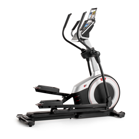
Thank you for selecting the revolutionary PROFORM reading this manual, please see the front cover of this ® ENDURANCE 520 E elliptical. The ENDURANCE 520 manual. To help us assist you, note the product model E elliptical provides an impressive selection of features number and serial number before contacting us. -
Page 5: Part Identification Chart
PART IDENTIFICATION CHART Use the drawings below to identify the small parts needed for assembly. The number in parentheses below each drawing is the key number of the part, from the PART LIST near the end of this manual. The number following the key number is the quantity needed for assembly. -
Page 6: Assembly
ASSEMBLY • Assembly requires two persons. • In addition to the included tool(s), assembly requires the following tools: • Place all parts in a cleared area and remove the one Phillips screwdriver packing materials. Do not dispose of the packing materials until you finish all assembly steps. - Page 7 3. Press the Cover Mounts (106) on the underside of the Rear Stabilizer Cover (15) into the Rear Stabilizer (2). 4. With the help of a second person, place some of the packing materials (not shown) under the front of the Frame (1). Have the second per- son hold the Frame to prevent it from tipping while you complete this step.
- Page 8 5. Orient the Upright (4) as shown. Have a second Wire person hold the Upright near the Frame (1). See the inset drawing. Locate the wire tie in the lower end of the Upright (4). Tie the wire tie to the Main Wire (110).
- Page 9 7. Using a plastic bag to keep your fingers clean, apply some of the included grease to the Pivot Axle (35) and to two 16mm Wave Washers (54). Insert the Pivot Axle (35) through the Upright (4) and center it. Tip: It may be helpful to use a rubber mallet.
-
Page 10: While A Second Person Holds The Console (7
9. Untie and discard the wire tie on the Main Wire (110). While a second person holds the Console (7) near the Upright (4), connect the wires on the Console to the Main Wire (110) and to the Pulse Sensor Wires (63). Insert the excess wire into the Upright (4) or into the Console (7). - Page 11 11. Orient the Right Pedal Arm (58) as shown. Apply grease to the axle on the Right Pedal Arm (58). Attach the Right Pedal Arm (58) to the Right Roller Arm (59) with an M8 x 14mm Shoulder Screw (120), a Small Axle Cover (55), and an M8 Washer (97).
- Page 12 13. Orient the Rear Upright Cover (81) as shown. Attach the Rear Upright Cover (81) to the Upright (4) with four M4 x 16mm Screws (101); start all the Screws, and then tighten them. Next, orient the Front Upright Cover (117) as shown.
- Page 13 15. Identify the Right Leg Inner Cover (83) and orient it as shown. Attach the Right Leg Inner Cover (83) to the Right Upper Body Leg (60) with an M4 x 16mm Screw (101) and an M5 Washer (32). Next, identify the Right Leg Outer Cover (69) and orient it as shown.
- Page 14 17. Orient the Rear Console Cover (80) as shown. Attach the Rear Console Cover (80) to the Upright (4) with two M4 x 16mm Screws (101). Next, orient the Front Console Cover (79) as shown. Attach the Front Console Cover (79) around the Upright (4) by pressing the hooks on the Rear Console Cover (80) onto the tabs on the Front Console Cover.
- Page 15 19. Plug the Power Adapter (119) into the receptacle on the frame of the elliptical. Note: To plug the Power Adapter (119) into an outlet, see HOW TO PLUG IN THE POWER ADAPTER on page 16. 20. Make sure that all parts are properly tightened before you use the elliptical. Extra parts may be included. Place a mat beneath the elliptical to protect the floor.
-
Page 16: How To Use The Elliptical
HOW TO USE THE ELLIPTICAL HOW TO PLUG IN THE POWER ADAPTER HOW TO LEVEL THE ELLIPTICAL IMPORTANT: If the elliptical has been exposed to If the elliptical rocks cold temperatures, allow it to warm to room tem- slightly on your perature before you plug in the power adapter. - Page 17 HOW TO CHANGE THE INCLINE OF THE RAMP To vary the motion of the pedals, you can change the Upper incline of the ramp. To raise the ramp, simply pull the Body Arms ramp handle upward to the desired incline level. Handlebars Latch Button...
- Page 18 CONSOLE DIAGRAM FEATURES OF THE CONSOLE You can even connect your personal audio player to the console sound system and listen to your favorite The advanced console offers an array of features music or audio books while you exercise. designed to make your workouts more effective and enjoyable.
- Page 19 HOW TO USE THE MANUAL MODE Calories (Cals.)—This display mode will show the approximate number of calories you have burned. 1. Begin pedaling or press any button on the console to turn on the console. Calories per Hour (Cals./Hr)—This display mode will show the approximate number of calories you When you turn on the console, the display will turn are burning per hour.
-
Page 20: Same Time
As you exercise, the workout intensity level bar heart rate monitor with your palms resting against will indicate the approximate intensity level of your the contacts. Avoid moving your hands or grip- exercise. ping the contacts tightly. When your pulse is detected, a heart symbol will appear in the display, one or two dashes will appear, and then your heart rate will be shown. - Page 21 HOW TO USE AN ONBOARD WORKOUT the next segment, the resistance level and/or target rpm will appear in the display for a few seconds 1. Begin pedaling or press any button on the to alert you. The resistance of the pedals will then console to turn on the console.
- Page 22 HOW TO USE THE SOUND SYSTEM THE OPTIONAL CHEST HEART RATE MONITOR To play music or audio books through the console Whether your sound system while you exercise, plug a 3.5 mm male goal is to to 3.5 mm male audio cable (not included) into the jack burn fat or to on the console and into a jack on your personal audio strengthen your...
- Page 23 HOW TO CONNECT YOUR SMART DEVICE TO THE HOW TO CONNECT YOUR HEART RATE MONITOR CONSOLE TO THE CONSOLE The console supports BLUETOOTH connections to The console is compatible with all BLUETOOTH Smart smart devices via the iFit app and to compatible heart heart rate monitors.
- Page 24 HOW TO CHANGE CONSOLE SETTINGS Contrast Level—The currently selected contrast level will appear in the display. Press the Quick 1. Select the settings mode. Resistance increase and decrease buttons to adjust the contrast level. To select the settings mode, press the gear button. The settings information will appear in the display.
-
Page 25: Maintenance And Troubleshooting
MAINTENANCE AND TROUBLESHOOTING MAINTENANCE Next, locate the Reed Switch (38). Turn the Pulley (19) until a Magnet (43) is aligned with the Reed Switch. Regular maintenance is important for optimal performance and to reduce wear. Inspect and properly tighten all parts each time the elliptical is used. Replace any worn parts immediately. - Page 26 HOW TO ADJUST THE DRIVE BELT See EXPLODED DRAWING C on page 35. Identify the Left and Right Shields (73, 74). Remove the If the pedals slip while you are pedaling, even while M4 x 25mm Screws (124), the M4 x 19mm Screws the resistance is adjusted to the highest level, the drive (5), and the M4 x 48mm Screw (107) from the Left and belt may need to be adjusted.
-
Page 27: Exercise Guidelines
EXERCISE GUIDELINES Burning Fat—To burn fat effectively, you must exer- WARNING: cise at a low intensity level for a sustained period of Before beginning this time. During the first few minutes of exercise, your or any exercise program, consult your physi- body uses carbohydrate calories for energy. - Page 28 SUGGESTED STRETCHES The correct form for several basic stretches is shown at the right. Move slowly as you stretch; never bounce. 1. Toe Touch Stretch Stand with your knees bent slightly and slowly bend forward from your hips. Allow your back and shoulders to relax as you reach down toward your toes as far as possible.
- Page 29 NOTES...
- Page 30 NOTES...
-
Page 31: Part List
PART LIST Model No. PFEVEL69716.0 R0616A Key No. Qty. Description Key No. Qty. Description Frame Roller Rear Stabilizer Pedal Arm Rear Cap Ramp Large Axle Cover Upright 16mm Wave Washer M4 x 19mm Screw Small Axle Cover Front Stabilizer Roller Arm Bushing Console Large Arm Bearing Roller Guide... - Page 32 Key No. Qty. Description Key No. Qty. Description M4 x 16mm Screw Disc Ring M8 Locknut Front Upright Cover M6 x 12mm Screw Shield Cover Cap M10 x 122mm Screw Power Adapter M10 Split Washer M8 x 14mm Shoulder Screw Cover Mount Tablet Holder M4 x 48mm Screw...
-
Page 33: Exploded Drawing
EXPLODED DRAWING A Model No. PFEVEL69716.0 R0616A... - Page 34 EXPLODED DRAWING B Model No. PFEVEL69716.0 R0616A...
- Page 35 EXPLODED DRAWING C Model No. PFEVEL69716.0 R0616A...
-
Page 36: Ordering Replacement Parts
ORDERING REPLACEMENT PARTS To order replacement parts, please see the front cover of this manual. To help us assist you, be prepared to provide the following information when contacting us: • the model number and serial number of the product (see the front cover of this manual) •...
Need help?
Do you have a question about the ENDURANCE 520 E and is the answer not in the manual?
Questions and answers
My power cord broke and have ordered 4-5 different replacements and none of them power up the machine
Hi, my power cable is broken. How do I get a replacement? Is there a model number?
You can obtain a replacement power cable for the ProForm ENDURANCE 520 E by purchasing a compatible AC adapter listed as "AC Adapter for ProForm Endurance 520E Smart Strider 495 Elliptical DC Power Supply Charger Cord Cable, 5 Feet, with LED Indicator." This adapter is labeled as a compatible replacement and is available for purchase online. Make sure the model number (PFEVEL69716.0) matches before buying.
This answer is automatically generated